Table of Contents
Advertisement
Advertisement
Table of Contents

Related Manuals for VOTEM VP-700


Summary of Contents for VOTEM VP-700
- Page 1 2.09 2022.01.04...
- Page 2 VP-700 Characteristics and Principles of VP-700 Thank you for purchasing the VP-700 (Multi Parameter Patient Monitor) VP-700 provides a variety of information about the patient by numeric values and waveforms. VP-700 has features as follows ※ Basic functions of Patient measuring...
-
Page 3: Table Of Contents
Electrical safety precautions ----------------- ◆ Pacemaker Detection ----------------------- ◆ Composition of VP-700 ----------------------- ◆ Respiration Measurement ------------------ ◆ How to set VP-700 ---------------------------- ◆ HRV Measurement --------------------------- ◆ Components of VP-700 ----------------------- ◆ NIBP Display----------------------------------- ➢ Front & Operation panel ------------------- ◆... -
Page 4: Preface
User Manual VP-700 Preface Thank you for purchasing the VP-700. ⚫ To ensure safety operating and long-term performance stability, it is essential that you fully understand the functions, operating and maintenance. Read operating manual carefully before using. ⚫ Please keep this manual in a place where it is easy to find and check its function. -
Page 5: Warranty
Warranty … ⚫ VOTEM warrants to the purchaser that VP-700 will be free from defects in material and/or workmanship for one year from the date of delivery but In case of consumable items (ex: LCD, battery, printer, NIBP valve etc.) and accessories will be free from defects in material and /or workmanship for 6 months from the date of purchasing or the date of first operation. -
Page 6: Before Reading This Manual
User Manual VP-700 Before reading this Manual Some symbols are used in this manual to help users or patients use this product safely and appropriately and to prevent any risk to patients or damage to materials. Please read and understand all warnings and precautions. -
Page 7: Safety Precaution
User Manual VP-700 Safety Precaution ⚫ Do not operate or store the equipment under the following environments. Avoid placing in an area exposed to Avoid exposure to direct sunlight moisture. Do not touch the equipment with wet- hand. Avoid placing in an area where there is a high variation of temperature. - Page 8 Do not disjoint or disassemble the Power off when the equipment is not fully installed. Otherwise, equipment could be equipment. Votem takes no responsibility damaged. of it Pull out the power cord with holding the plug, not the cord.
-
Page 9: Electrical Safety Precautions
Electrical safety precautions Please check followings before using the system ◆ VP-700 is intended only to measure and assess patient state. It must be used in conjunction with Clinical signs and symptoms when diagnosis is made. ◆ Only qualified personnel should use the Patient monitor. Please read the user’s manual before use. - Page 10 User Manual VP-700 Electrical safety precautions Please check followings before using the system ◆ To prevent electric noise during use, the product should be installed apart from dynamo, X-ray equipment, broadcast equipment or portable cables. An inaccurate result may occur when these equipment are placed near the product.
- Page 11 Electrical safety precautions Please check followings before using the system ◆ VP-700 is “Class IIb” equipment. ◆ It is type “CF grade” for ECG, Resp, IBP and “BF grade” for EtCO2, SpO2, NIBP and Temp. ◆ The noise level is“ B” Class according to the IEC/EN 60601-1 (Safety of Electric Medical Product), and the noise redemption is “B”...
-
Page 12: Composition Of
User Manual VP-700 Composition of VP-700 Kindly check all the items inside the package before installation. Standard Accessories ECG Cable Main 1 set 5 lead type (1EA) SpO2 Finger Probe 3M Electrode (1EA) (5 PCS/1set) NIBP Hose (1EA) Quick Manual... -
Page 13: How To Set
VP-700 How to set VP-700 ◆ Precautions for Settings Pay attention when setting VP-700 for the following points ➢ Use VP-700 under conditions of 10℃∼35℃ of circumstantial temperature and 30%∼85% humidity. ➢ Check the connection status of the power cord. -
Page 14: Components Of
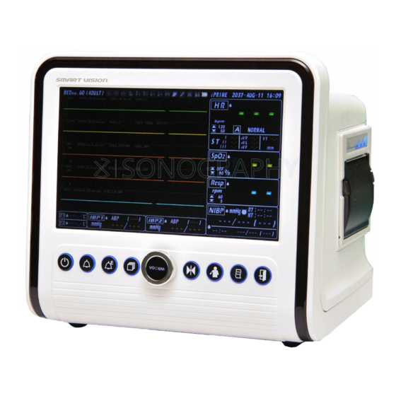
User Manual VP-700 Components of VP-700 ◆ Front & Operation Panel (1) Power Button (6) FREEZE Button (2) ALARM ON/OFF Button (7) NIBP START/STOP Button (3) EVENT SAVE Button (8) PRINT Button (4) SCREEN Button (9) EXIT Button (5) MENU Button... -
Page 15: Right Side
User Manual VP-700 Components of VP-700 ◆ Right Side (Printer Option) (1) PRINT POWER LED (3) PRINT FEED BUTTON (2) PRINT ERROR LED (4) PRINT DOOR... -
Page 16: Left Side
User Manual VP-700 Components of VP-700 ◆ Left Side (1) ECG/RESP Connection Terminal (5) TEMP 2 Connection Terminal (Optional) (2) SpO2 Connection Terminal (6) CO2 Connection Terminal (Optional) (3) NIBP Connection Terminal (7) IBP1 Connection Terminal (Optional) (4) TEMP 1 Connection Terminal... -
Page 17: Left Side (F3000 Temp-Optional)
User Manual VP-700 Components of VP-700 ◆ Left Side (F3000 Temperature – Optional) ● ● ● ● ● ● (1) Temp Probe sensor (4) ECG/Resp Connection Terminal (Option) (2) Probe Chamber (5) SpO2 Terminal (3) F3000 Side Cover (6) NIBP Connection Terminal... -
Page 18: Back Side
User Manual VP-700 Components of VP-700 ◆ Back Side Handle LAN Port Ground Pole DC 12V Input (Option) MAIN Power Switch SD Card Slot AC Power Input Port (10) ECG Out Port (Option) RS232 Port (11) IBP Out Port (Option) -
Page 19: Description Of Product Symbols
User Manual VP-700 Description of Product Symbols Symbol Description Symbol Description Type CF Product, Alarm On/Off Defibrillation protected Type BF Product, Alarm Event Defibrillation protected Screen Change(Screen) Type BF Product Attention, Warning consult Stop Waveforms (Freeze) Accompanying documents Non Invasive Blood Pressure... - Page 20 User Manual VP-700 Explanation of screen You can check setting information on the LCD screen. : Bed Number : Respiration Alarm Limits : IBP Mean : Default set : Respiration Measurement : IBP Systolic : Alarm and Function Icon : NIBP Auto Interval...
- Page 21 User Manual VP-700 You can check setting Explanation of screen (VP-700 SNT) information on the LCD screen. : SpO2 Version : SpO2 Pulse Rate : SpO2 Measurement : F3000 Temperature Measurement : NIBP Version : NIBP Measurement : SpO2 Wave...
- Page 22 VP-700 Explanation of screen You can check setting information on the LCD screen. ◆ VP-700 provides 6 different screens to use “Screen” button. 1. Main Screen 2. ECG 7 leads Screen (Use for ECG 5 leads cable) 4. Numeric Screen 3.
-
Page 23: Explanation Of Screen
User Manual VP-700 Explanation of screen You can check setting information on the LCD screen. ICON Meaning How to display During the save : Fixed EVENT Save If the saving data is existed : Flickers at 1-second interval Alarm Suspend : Automatically Flickers at 1-second interval stops after 1~5 minutes. -
Page 24: How To Use Vp-700
User Manual VP-700 It is essential that you fully understand the How to use VP-700 functions before using Turn on the main power switch on the back of the product. Push the power switch for 1~2 second. If you want to change the setting value etc. while using, push the Menu button to change the setting values per each measurement parameter. -
Page 25: Alarms
It is essential that you fully understand the functions before using Different alarms are provided in VP-700 for the sake of the user’s convenience. Please read carefully the contents of this section in order to learn how to interpret and react... - Page 26 User Manual VP-700 ➢ Audible Alarm When an alarm occurs, the measured value flashes. Alarm Category Tone Pitch Alert sounds ring 10 times. After 7 seconds, alert High Alarm ~ 976Hz sounds ring repeatedly. Alert sounds ring 3 times. After 20 seconds, alert...
-
Page 27: Alarm Setting
User Manual VP-700 Alarm Setting It is essential that you fully understand the functions before using ◆ How to set the alarm. To change the alarm setting, push the Menu switch once to select “Alarm”. Left/Right Turn of the Menu switch, select parameter. -
Page 28: Alarm Range
User Manual VP-700 Alarm Range It is essential that you fully understand the functions before using ◆ By operating as detailed above, you can change the setting range of the alarm for each Setting Range Parameter HIGH TYPE SETUP_SILENCE TIME... - Page 29 User Manual VP-700 It is essential that you fully understand the functions Silence Alarm Time set before using Alarm doesn’t sound for setting time when the alarm key is pressed. Monitor displays “ alarm pause” while the icon is blinking Alarm doesn’t sound when the key is...
-
Page 30: Trend Display
User Manual VP-700 Trend Display It is essential that you fully understand the functions before using ● ● ● ● ● ● <Trend 화면> Description Description Trend Data Saving date, time TRACE 3 TRACE 1 Trend Data TRACE 2 Select Bar ◼... -
Page 31: Trend Data Check
TRACE on ‘Trend’ menu. ◼ VP-700 support graph trend data for easily check up patient status. ◼ VP-700 Trend data can save data for 7 days every 1 minute. NOTE (If you use SD CARD, you can save more patient’s information) To set interval time of Trend, select the INTERVAL on Trend menu. - Page 32 User Manual VP-700 Trend Data Check It is essential that you fully understand the functions before using To delete Trend and Event Data, select “INITIAL” on Trend menu. ◼ When you select “EXECUTE”, all of Trend Data would be deleted. Take attention to select it before the deletion.
-
Page 33: Trend Data Save & Load
User Manual VP-700 Trend Data Save & Load It is essential that you fully understand the functions before using If you want to save Trend Data into SD CARD, insert SD CARD into the SD CARD port on the back of the monitor. -
Page 34: Event Display
User Manual VP-700 It is essential that you fully understand the functions EVENT Display before using. Description Description Event Data list 0.2 second Analysis Bar Event Data Number Trace 4 wave Alarm display window Trace 3 wave Saving date and time of Event Data... -
Page 35: Event Data Check
User Manual VP-700 EVENT Data Check It is essential that you fully understand the functions before using To check Event Data, press “Screen button” one time of Trend screen. 1) Select the desired Data on Event Data List by turning “Menu button” and press “Menu button”... - Page 36 User Manual VP-700 EVENT Data Check It is essential that you fully understand the functions before using. To print out Event Data, select “PRINT” on Event Menu to set Channel 1/2/3 and Size, and press “Print button”. ◼ Channel 1/2/3 is the wave to be printed out.
-
Page 37: Setup Setting
User Manual VP-700 SETUP Setting It is essential that you fully understand the functions before using ◆ Please setup print, volume and language or default for user’s convenience. To change Setup, push Menu switch one time to select SETUP menu. - Page 38 User Manual VP-700 SETUP setting It is essential that you fully understand the functions before using Setup Menu Range Description NETWORK SET CENTRAL / HL7 Select the data linking method IP ADDRESS 192.168.10.XXX Monitor’s IP ADDRESS ADMISSION / DISCHARGE HL7 only when ADMISSION ON / OFF.
-
Page 39: Default Set
User Manual VP-700 Default Set When you select default setting, all of setting values are changed to the values saved at the factory. ◆ The default settings of the values can be used, without the need of changing the setting values of each parameter. - Page 40 User Manual VP-700 Default Set When you select default setting, all of setting values are changed to the values saved at the factory. Parameter Item Name Adult Neonate Pediatric 1st CH TRACE ON TRACE ON TRACE ON TRACE 2st CH...
- Page 41 User Manual VP-700 Default Set When you select default setting, all of setting values are changed to the values saved at the factory. Parameter Item Name Adult Neonate Pediatric 1st CH SPEED 12.5 mm/sec 12.5 mm/sec 12.5 mm/sec 2st CH...
-
Page 42: Printer Setting(Optional)
User Manual VP-700 Printer Setting(Optional) It is essential that you fully understand the functions before using. ◆ The patient’s information can be printed out using the printer To change print setup, push ‘Menu Switch’ one time to select “SETUP➔ PRINTER” menu. - Page 43 User Manual VP-700 Printer Setting(Optional) It is essential that you fully understand the functions before using ◆ Example of Printing data <Ex: Trend Printing> <Ex: Wave Printing> ◆ Loading Printer paper. Please replace papers when run out of. Open the printer door by pushing the button at the both side of the printer slightly as shown the figure below.
-
Page 44: Color Setting
User Manual VP-700 COLOR Setting It is essential that you fully understand the functions before using. This function is to change color of Wave of each Parameter and numeric value for user’s convenience. ◆ Wave & numeric value Color change method To change color of Wave &... - Page 45 Power & Battery Spec It is essential that you fully understand the functions before using Both AC and DC power is used for VP-700. Basically, AC power is used and a rechargeable battery is available for portable use. ◆ AC Power (100~240VAC) When AC power is plugged into the patient monitor, a light-green color lights up on the AC LED on the front.
- Page 46 User Manual VP-700 Power & Battery Spec It is essential that you fully understand the functions before using ➢ Normal lifetime for spontaneous discharge of battery The table below shows the lifetime for spontaneous discharge of the battery when the product is unused.
-
Page 47: Ecg Measurement
Check if the ECG cable is damaged before taking the ECG measurement. (A damaged ECG cable cannot protect the patient.) ◼ Use only a VOTEM genuine ECG Cable with the VP-700 Other ECG cables may cause improper performance and/or provide inadequate protection during defibrillation. - Page 48 User Manual VP-700 ◼ IEC 60601-2-27: 2005 6.8.2 aa)) 15 : The amplitude, pulse width and overshoot of pacemaker pulses that are rejected by the EQUIPMENT. : amplitude : ±4~±700mV, width : 0.2~2ms, overshoot : 0 ~ 4ms ◼ IEC 60601-2-27: 2005 6.8.2 bb)) 1) : performance specification square wave, 32kHz, 130mVp-p, 29.81uA...
- Page 49 NOTE ◼ In case of using ECG 5 Lead cable, you need to set menu 5 Leads at ECG Cable. VP-700 provide ECG 5 LEAD CABLE as standard. If you select 3 LEAD at “MENU ➔ ◼ ECG ➔ CONFIG ➔ CABLE”, ECG will not be measured.
- Page 50 User Manual VP-700 ECG Measurement It is essential that you fully understand the functions before using ◆ ECG Lead change change Lead waveform setting, push Menu button one time on Main screen. Select “ECG -> LEAD -> 1 st CH”...
- Page 51 User Manual VP-700 - FILTER - 1) 0.5Hz selection: used when baseline movement is severe and when ECG diagnosis (arrhythmia, ST) is not needed 2) 0.05 Hz selection: when baseline movement is not severe and when an electrocardiogram (arrhythmia, ST) is...
-
Page 52: Ecg Out (Optional)
It is essential that you fully understand the ECG Out Function (Optional) functions before using VP-700 provides ECG analog/pulse wave output from rear stereo connector. It can be used with defibrillator sync input or other medical devices. ※ Pacemaker, respiration signal is not supported. -
Page 53: St Analysis
ST form. ◼ VP-700 is designed to analyze ST Level independently each ECG Lead for ST I / II / III / aVR / aVL / aVF / V. (Another ST level is not affected by the other ) NOTE ◆... -
Page 54: Arrhythmia Analysis
◼ VP-700 may happen wrong alarm or not operate alarm for arrhythmia analysis sometimes. Because there are many various patients. The arrhythmia analysis is to use monitoring for patient’s rhythm and hospital staffs seriously pay attention for emergency CAUTION patient. - Page 55 PCV is detected before finishing T wave in the normal ECG Wave. R-on-T ◼ VP-700 provides 12 kinds arrhythmia analysis and 2 kinds alarms for arrhythmia. - High Alarm : VTAC, ASY - Low Alarm : PVC, BGM, TGM, TAC, SVT, BRD, VENT, VFIB, CPT, TPT, MIB, R on T NOTE ◼...
-
Page 56: Pacemaker Detection
PACEMAKER ICON in the upper screen is flickering and the red bar is displayed on the ECG wave. ◼ VP-700 is possible to recognize wrong signal for pacemaker detection. This product should be used for detecting the pacemaker existence. ◼ PACEMAKER PATIENTS. Rate... -
Page 57: Respiration Measurement
User Manual VP-700 Respiration Measurement It is essential that you fully understand the functions before using Changes in the chest impedance resulting from the patient’s respiration is measured and displayed as a waveform and the values will appear on the screen. - Page 58 User Manual VP-700 It is essential that you fully understand the Respiration Measurement functions before using ◼ Respiration signals are relatively more sensitive to interference from radiated electromagnetic signals. Do not rely entirely on the equipment. CAUTION ◼ Respiration is measured with the ECG and HR etc., using the ECG cable ◼...
-
Page 59: Hrv Measurement
User Manual VP-700 HRV Measurement It is essential that you fully understand the functions before using Autonomic nervous system affecting to cardiac pacemaker cell in sinoatrial node(SA node) decides heart rate. SA node is controlled by sympathetic and para-sympathetic nervous system. - Page 60 User Manual VP-700 HRV Measurement It is essential that you fully understand the functions before using ◆ How to diagnosis HRV distribution graph Normal status Hypertension, stressed statussympathomimetic Arrhythmia, excitation, sympathomimetic status Overstrain, geriatric, parasympathomimetic status...
-
Page 61: Nibp Display
◼ Use only a VOTEM NIBP Cuff with the VP-700. Other NIBP Cuff may cause improper performance. WARNING Do not put heavy things on hose during measurement. -
Page 62: Nibp Manual Measurement
It is essential that you fully understand the functions before using ◆ How to measure NIBP (Manual) Connect NIPB Hose VP-700 and the other side to NIBP Cuff Wrap NIBP Cuff around patient’s left arm. To Start measurement, push NIBP button ◼... -
Page 63: Nibp Auto Measurement
User Manual VP-700 NIBP Auto Measurement It is essential that you fully understand the functions before using ◼ Auto function will be canceled when changing INTERVAL setting during auto measurement. When the automatic measurement mode is cancelled, the user should reset the AUTO ◼... - Page 64 User Manual VP-700 NIBP Auto Measurement It is essential that you fully understand the functions before using. ◆ NIBP Auto (SHORT TERM AUTOMATIC MODE) Measurement Method Mode which canceled after measuring NIBP several times during setting time. To start the automatic (AUTO) NIBP measurement, select “NIBP ➔...
-
Page 65: Nibp Error Message
User Manual VP-700 It is essential that you fully understand the NIBP Error Message functions before using. In case the error messages below are displayed during NIBP measurement, please refer to the descriptions of the message and take the proper steps. -
Page 66: Change Of Nibp Unit
User Manual VP-700 Change of NIBP Unit It is essential that you fully understand the functions before using. ◆ How to change the unit of blood pressure To change the unit of blood pressure, select UNIT in NIBP menu and set the desired unit. -
Page 67: Venous Stat
User Manual VP-700 VENOUS STAT Function It is essential that you fully understand the functions before using. ◆ This function is to find vein easily by controlling flow of vein with maintaining pressure to Cuff constantly for the patient who has difficulty to find vein. -
Page 68: Nibp Trend Screen
User Manual VP-700 NIBP TREND SCREEN It is essential that you fully understand the functions before using. ◆ NIBP TREND DATA check method by using NIBP TREND SCREEN Select “NIBP ➔ TREND ➔ SCREEN ➔ ON” on MENU. NIBP TREND SCREEN ◆... -
Page 69: Spo2 Measurement
User Manual VP-700 SpO2 Measurement It is essential that you fully understand the functions before using ◆ The concentration of oxygen saturation means the saturation level of hemoglobin which can transport the oxygen of the arterial blood. The current transport level for the capacity of hemoglobin to transport the oxygen is expressed as a percentage. - Page 70 User Manual VP-700 SpO2 Measurement It is essential that you fully understand the functions before using ◆ SpO2 Measurement Display Description Description SpO2 Waveform Speed, Size SpO2 Perfusion Index SpO2 Waveform SpO2 Pulse Bar SpO2 Alarm range SpO2 Measurement Numeric ◆...
- Page 71 User Manual VP-700 SpO2 Measurement It is essential that you fully understand the functions before using ◆ Change SpO2 Waveform speed and size To change SpO2 waveform size, Push Menu button one time to select “SpO2 -> Gain” To change SpO2 waveform speed, Push Menu button one time to select “SpO2 ->...
-
Page 72: Apg Measurement
User Manual VP-700 APG Measurement It is essential that you fully understand the functions before using APG (Accelerated Plethysmogram)? ◆ ➢ The Pulse wave made recorded to the wave of chest wall and large blood vessel by heart rate. ➢ Among of pulse waves, the volume plethysmongraphy is that expansion and contraction of ductus arteriosus is caused by pressure variation of peripheral aneurysm of fingertips, tiptoe and earflap. - Page 73 User Manual VP-700 APG Measurement It is essential that you fully understand the functions before using APG (Accelerated Plethysmogram) application ◆ ➢ We can presume the age of blood vessel by elasticity of blood vessel with APG. ➢ APG measured value: It is expressed to 1~8 and the age range of blood vessel too.
-
Page 74: Temperature Measurement
User Manual VP-700 Temperature Measurement It is essential that you fully understand the functions before using ◆ Changes in impedance according to the change in the patient’s body temperature is perceived by the temperature sensor, and then displayed numerically on the screen after a series of calculations. -
Page 75: F3000 Temperature Measurement
User Manual VP-700 F3000 Temperature Measurement essential that you fully understand the functions before (Optional) using ◆ F3000 Temperature Measurement Screen Normal Measurement Screen Error Measurement Screen ◆ F3000 Temperature Type Menu Screen (Oral Mode) - Page 76 User Manual VP-700 ◆ F3000 Temperature Type Menu Screen (Rectal Mode) ◆ As a result of the information above, only the following Measurement commands are valid: Probe Type Message Measurement Type O F X M Oral Fast Predict O P X M...
- Page 77 User Manual VP-700 ➢ Fast Predict Mode Always attempts to use the Fast Prediction algorithm on any patient temperature measurement. If the output of this prediction is too low (below 36.4111℃) or is in the Fever range (above 37.6111℃), the unit will transition to Standard Predict Mode. The only valid command for Fast Predict Mode is “OFXM”.
- Page 78 User Manual VP-700 ◆ Oral & Axillary Temperature Taking Make certain that the Blue isolation chamber/probe unit is attached. Withdraw probe and apply a probe cover. The thermometer turns on automatically. ◼ Accurate body temperature readings can only be obtained in one of these two “heat pocket”...
- Page 79 User Manual VP-700 Securely hold the probe in place until the temperature is displayed. For Axillary temperatures, have the patient raise the arm, then place the probe tip in the axilla. Press gently to assure good contact. For the most accurate temperature the...
- Page 80 User Manual VP-700 After returning the probe to the probe well, the temperature is stored for recall until the probe is once again withdrawn. If the probe is returned to the probe well before the “long beep” is heard, no temperature will be stored for the recall function.
- Page 81 User Manual VP-700 ◆ Rectal Temperature Taking Make certain that the Red isolation chamber/probe unit is attached. Withdraw probe and apply a probe cover. The thermometer turns on automatically. Apply lubrication if desired. Insert the probe into the patient’s rectum. To ensure proper tissue contact, angle the probe slightly after insertion.
- Page 82 User Manual VP-700 ◆ Cleaning and Sterilization The entire device may be easily wiped clean. Water temperature should not exceed 130° F (55° C). Do not submerge or soak under water. A mild detergent may be added to water. Use of cleaners such as Spray NineTM*, PhisohexTM*, HibiclensTM*, or Vesta-SydeTM*, CidexTM* may result in damage to the thermometer case.
-
Page 83: Ibp Measurement
User Manual VP-700 IBP Measurement (Optional) It is essential that you fully understand the functions before using Arterial Blood Pressure is the pressure exerted by the blood against the walls of the arterial vessels. The cardiac cycle consists of a period of relaxation called Diastole, during which the heart fills with blood, followed by a period of contraction called Systole. - Page 84 User Manual VP-700 IBP Measurement (Optional) It is essential that you fully understand the functions before using ◼ A transducer which can be protected from electric shock and electrical impulses should be used. It can be used during the electric operation of the device.
- Page 85 User Manual VP-700 It is essential that you fully understand the IBP Measurement (Optional) functions before using “Hold the backside of the clear cover surrounding the connector, and connect the converter to the reusable monitor interface. ◼ To remove the converter from the cable, push the tap gently inside the clear cover and then separate the reusable interface cable.
- Page 86 User Manual VP-700 IBP Measurement (Optional) It is essential that you fully understand the functions before using Twist the sterilized solution bag lightly using a drip chamber spike Open the roller clamp and remove the air inside the bag completely by squeezing using an infusion set or a needle inserted into the injection port in the back.
- Page 87 User Manual VP-700 It is essential that you fully understand the IBP Measurement (Optional) functions before using << Priming and Tips >> ◼ Priming should be done slowly! - Slow priming will lessen the effort to remove air bubbles afterward.
- Page 88 User Manual VP-700 It is essential that you fully understand the IBP Measurement (Optional) functions before using ◆ Table for labels according to the site of measurement Label Site Measurement Artery group throughout the whole body Arterial blood pressure (systemic)
-
Page 89: Ibp Out (Optional)
IBP Wave Out Function (Optional) understand the functions before using ※ VP-700 provides IBP analog wave output from rear stereo connector. It can be used with defibrillator sync input or other medical devices. ※ Pacemaker, respiration signal is not supported. -
Page 90: Etco2 Measurement (Optional)
◆ Mainstream, Sidestream CO2 Gas Measurement The Respironics, CAPNOSTAT Mainstream CO2 and LOFLO Sidestream module can be connect in VP-700. CO2 module provides the function of ETCO2 and the function to measure respiratory CO2 and respiration numbers using the small filterline based on a small lumen type filterline. - Page 91 User Manual VP-700 It is essential that you fully understand EtCO2 Measurement (Optional) the functions before using ◆ Mainstream, Sidestream CO2 Calibration ◼ CO2 Calibration should be executed at the cases below. ◆ New patient ◆ When turning on/off the patient monitor ◆...
- Page 92 Respiration numeric is automatically changed when EtCO2 is measured. It will be displayed the changes of impedance. EtCO2 and FiCO2 will be displayed on VP-700 screen after 15 second when it detects proper input. EtCO2 waveform and data will be displayed. If waveform is not displayed on the screen, change setting menu “Menu →...
- Page 93 Respiration numeric is automatically changed when EtCO2 is measured. It will be displayed the changes of impedance. EtCO2 and FiCO2 will be displayed on VP-700 screen after 20 second when it detects proper input. EtCO2 waveform and data will be displayed. If waveform is not displayed on the screen, change setting menu “Menu →...
- Page 94 User Manual VP-700 It is essential that you fully understand EtCO2 Measurement (Optional) the functions before using ◆ Message description Message Description EtCO2 Module is connected to monitor and ready SENSOR WARM_UP to operate. SAMPLE LINE is disconnected or disassembled SAMPLE LINE DISCONNECT from Module during measurement.
-
Page 95: Auxiliary Power Unit (Optional)
It is used as a power source for APs with DC 9V 0.5A or less. ◆ Connection info This is the power output terminal. Use the connector provided by VOTEM ◼ Do not use it for any other purpose. ◼ Check the rated power of the AP to be used. -
Page 96: Before Requesting After-Sales Service
User Manual VP-700 Before Requesting After-Sales Service… This section shows how to treat simple problems encountered during use. ▣ Problems in Display Sign How to treat 1. Check if the main S/W at the back of the product is on. - Page 97 User Manual VP-700 ▣ Problems in SpO2 Measurement Sign How to treat 1. Check if the probe is affected by strong light in the area. 2. Check if the connection is normal; if the red light of the sensor flickers or does not turn on, it is an inferior probe.
- Page 98 User Manual VP-700 ▣ Problems in IBP Measurement Sign How to treat Blood pressure measurement Pour out the contents of the tube carefully and remove is unstable. the bubble, then shorten the tubing length. Severe noise or bias in the Do not shake or touch the connection area of the IBP waveform.
-
Page 99: Product Specifications
User Manual VP-700 Product Specifications ◼ Measurement parameters 3ch ECG, NIBP, SpO2, 2IBP, 2 Temp, EtCO2 or Respiration. PROCESSING PARAMETERS: HR, NIBP(Systolic/Diastolic/Mean pressure), SpO2 Saturation, Pulse rate, Respiration, IBP, Temp, EtCO2 ◼ Monitor Performances specifications TFT Color LCD Display Waveform Display Method : Scroll... - Page 100 User Manual VP-700 DC OFFSET : -300mV to 300mV ARRHYHMIA Detect (TAC, BRD, PVC, VTAC, ASY, BGM, TGM, VENT, VFIB, COP, TPT, MIB, R on T) ST Analysis Range: -9.9mV ~ +9.9mV, Resolution: 0.1mV Pacemaker Detect HR Claculation : 4 ~ 16 wave Defibrilator Sync QRS WIDTH: 100, 200, 300, 400, 600, 800ms, AUTO.
- Page 101 User Manual VP-700 Auto Pressure : Manual, Automatic ( 2, 3, 4, 5, 10, 15, 30 min. and 1, 2, 4, 8 ,12 hours interval) NIBP STAT: 5 ~ 15 min NIBP VENOUS STAT: 50 ~ 200 mmHg NIBP MAX LIMIT: 70 ~ 300 mmHg ◼...
- Page 102 User Manual VP-700 - CO2 accuracy : 0 – 40 mmHg → ±2 mmHg 41 – 70 mmHg → ±5% of reading 71 – 100 mmHg → ±8% of reading 101 – 150 mmHg → ±10% of reading - Respiration Measurement Range : 0 ~ 150 BPM - Respiration Accuracy : ±1 BPM...
- Page 103 User Manual VP-700 ◼ F3000 Temperature – Optional - ACCURACY: Quick Mode: (Oral) +/- 0.3℃ (+/-0.6℉) Standard Mode: (Axillary/Rectal) +/- 0.1℃ (+/-0.2℉) Direct Mode: +/- 0.1℃ (+/-0.2℉) - MEASUREMENT RESPONSE TIME: Quick Mode: 3-5 seconds(non-fever temps) (Oral) 8-10 seconds(fever temps) (Oral)
- Page 104 User Manual VP-700 ◼ Interface - RS-232C port - LAN Port ( CENTRAL / HL7 ) - SD CARD - ECG Output port (Option) ◼ Physical Specifications Weight Composition Size (With 3S1P battery ESN1T 2.93 kg (6.46 lb) ESN1T + Printer 3.10 kg (6.84 lb)
- Page 105 User Manual VP-700 ◼ Optional Accessories - Trolley (=Cart) ECG 3 leads Cable SpO2 Extension Cable - Wall Mount Press Measuring Kit - Disposable SpO2 Sensor Printer Module - Battery 11.1V, 4400mAh Roll Paper(18M) - EtCO2 Kit set Ground Cable...
-
Page 106: Safety
EMI(Electromagnetic Interface) requirements, use of this system in the presence of an electromagnetic filed can cause momentary degradation of the vital Signal. If this occurs often, Votem suggests a review of the environment in which the system is begin use, to identity possible sources of radiated emissions. These emissions could be from other electrical devices used within the same room or an adjacent room. - Page 107 User Manual VP-700 Safety The VP-700 monitor is intended for use in the specified electromagnetic environment. The customer or the user of the VP-700 should assure that it is used in such an environment as described below; ⚫ Electromagnetic emission...
- Page 108 Voltage variations for 0.5cycle for 0.5cycle hospital environment. If the user On power supply of the VP-700 monitor image Input lines 40% U 40% U intensifier requires continued (60% dip in U (60% dip in U...
- Page 109 RF transmitters, an electromagnetic site survey should be considered. If the measured field strength in the location in which the VP-700 is used exceeds the applicable RF compliance level above, the VP-700 should be observed to verify normal operation. If abnormal perform- ance is observed, additional measures may be necessary, such as re-orienting or relocating the VP-700.
- Page 110 Recommended separation distance between portable and mobile RF communications equipment and the VP-700 monitor. This VP-700 monitor is intended for use in an electromagnetic environment in which radiated RF disturbances are controlled. The customer or the user of the VP-700 monitor can help Prevent...
- Page 111 Test level level The VP-700 monitor is intended for use in the electromagnetic environment specified below. The customer or the user of the VP-700 monitor should assure that it is used in such an electro -magnetic environment. Conducted RF 3 Vrms...
-
Page 112: Network Appendix
User Manual VP-700 NETWORK Appendix CENTRAL SET 1) SETUP -> NETWORK SET -> CENTRAL Select 2) SETUP -> SET IP -> LOCAL IP, HOSET IP, GATEWAY, SUBNET, PORT . Etc set. 1) LAN Connecting the cables 2) IP should not be overlapped with other patient monitor. - Page 113 User Manual VP-700 It is essential that you fully NETWORK Appendix understand the functions before using ※ "ADMISSION IP" and "DATA IP" can be the same according to the hospital network environment. ※ Measurement data should be available. Only then will the DATA be sent to the server..
-
Page 114: Cart, Wall Mount Appendix
User Manual VP-700 CART, Wall mount Appendix... - Page 115 User Manual VP-700...
- Page 116 << EC Authorized Representative >> C/Horacio Lengo Nº 18 CP 29006, Málaga-Spain Tel: +34951214054 Fax: +34952330100 E-Mail : Info@cmcmedicaldevices.com VOTEM CO., LTD << / Head Office >> Manufacturer 27, Geodudanji 1-gil, Dongnae-myeon, Chuncheon-si, Gangwon-do, Korea (zip. 24398) Tel: +82-33-910-0701, Fax: +82-33-911-0701...
Need help?
Do you have a question about the VP-700 and is the answer not in the manual?
Questions and answers