Table of Contents
Advertisement
OPERATION MANUAL
OPERATION MANUAL
MITSUBISHI TRANSPORT REFRIGERATION UNIT
TU100SAE
TU100SAEM
This operation manual is
intended to provide users
with a good knowledge to
use Mitsubishi Refrigeration
Unit safely.
Operate or service the
refrigeration unit only after
you have read this manual
and understand its
contents.
Carefully store this manual
in a xed place so that it is
immediately available for
your reference when you
need it.
TSJ012A181A
YEAR:2016
Advertisement
Table of Contents

Related Manuals for Mitsubishi TU100SAE


Summary of Contents for Mitsubishi TU100SAE
- Page 1 OPERATION MANUAL OPERATION MANUAL MITSUBISHI TRANSPORT REFRIGERATION UNIT TU100SAE TU100SAEM This operation manual is intended to provide users with a good knowledge to use Mitsubishi Refrigeration Unit safely. Operate or service the refrigeration unit only after you have read this manual and understand its contents.
-
Page 2: Important Information
Thank you for your purchase of Mitsubishi Transport Refrigeration Unit. Purpose of use and application This Refrigeration Unit is intended to carry the cargo (with the exception of volatile, inflammable, hazardous and corrosive matters) on a transportation vehicle, keeping the inside container temperature at a certain degree. -
Page 3: Operation Manual
Operation manual ● This operation manual is prepared for people who speaks English. In case that person whose native language is not English handles this refrigeration unit, he or she must be instructed on safety by the customer. Furthermore, the warning labels described in their native language must be prepared and stuck on the proper places. -
Page 4: Table Of Contents
Contents Purpose of use and application - I Prevention of start during inspection work ----------------- 23 Important information ------------ I Clothing and protective equipment -- 23 Operation manual ----------------II Handling of grease and oil ----- 23 For disposal -----------------------II When abnormal conditions are Contents -------------------------- III detected ------------------------- 23 For emergency ------------------ 23... - Page 5 Manual defrost operation ------ 47 Periodic inspection ------------- 65 Periodic inspection check sheet -- 66 Starting ------------------------------- 47 Stopping ----------------------------- 47 Details of applicable oils and cooling water-------------------- 68 Setting the ON timer ----------- 48 Power supply system ---------- 68 Setting the OFF timer ---------- 50 Self diagnosis operation 8 Operation or stop for long...
-
Page 6: Function Of Refrigeration Unit
1 Function of Refrigeration Unit This refrigeration unit has following functions. (1) Drive switching function This is the function to switch the drive (engine/motor) depending on whether the commercial power supply is connected or not. Refer to page 38 for how to switch the drive. (2) Operation pattern selection function This is the function to switch operation pattern (automatic start/stop operation/continuous operation). - Page 7 1 Function of Refrigeration Unit (5) Timer operation function This is the function to set starting time and stopping time of the operation . Refer to pages from 48 to 51 for how to set. (6) Self diagnosis operation function [PTI (Pre Trip Inspection) operation] This is the function to diagnose the refrigeration unit automatically if it has any trouble or not.
-
Page 8: Name Of Each Part
2 Name of each part Arrangement plan for main parts ■Single specification (TU100SAE) Evaporator unit Cabin controller Condensing unit Fuel pump Control box Fuel tank Refrigerant piping Water separator Battery Actual locations of above units, etc. should be checked beforehand because they could vary depending on vehicle models, or other. - Page 9 2 Name of each part ■Multiple specification (TU100SAEM) Front room evaporator unit Battery Rear room evaporator unit Cabin controller Condensing unit Fuel pump Control box Fuel tank Refrigerant piping Water separator Actual locations of above units, etc. should be checked beforehand because they could vary depending on vehicle models, or other.
-
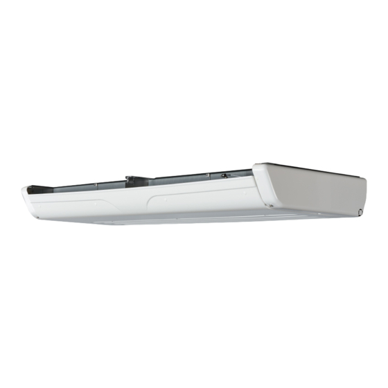
Page 10: Evaporator Unit
2 Name of each part Evaporator unit ■Single specification (TU100SAE) •Thin type : TU100SAE-EVX Inside of view "A" Supply air outlet for evaporator Evaporator coil Electric heater (Optional) Electronic expansion valve Evaporator fan motor - 5 -... - Page 11 2 Name of each part ■Multiple specification (TU100SAEM) •Thin type (L) : TMEVX-L •Thin type (M) : TMEVX-M •Thin type (S) : TMEVX-S Inside of view "A" Supply air outlet for evaporator Evaporator coil Electric heater (Optional) Electronic expansion valve Evaporator fan motor - 6 -...
-
Page 12: Condensing Unit
2 Name of each part Condensing unit ■Single specification (TU100SAE-CNE) / Multiple specification (TU100SAEM-CNE) Front panel Motor Commercial power socket Dryer Latch Oil filter Reservoir tank Fuel filter Compressor Air cleaner Alternator Control box Engine Main switch Radiator & condenser... -
Page 13: Cabin Controller
2 Name of each part Cabin controller ■Multiple specification (TU100SAEM) ■ マルチ仕様 (TU100SAM) RUN/STOP switch Starts or stops the refrigeration unit. MODE switch Selects the normal display screen or the setting display screen. Displays the screen while the refrigeration unit is stopped. UP switch Changes the setting temperature, setting screens and setting values. -
Page 14: Digital Display Area
2 Name of each part Digital display area Explanation of display Upper digital display Displays the setting temperature during operation. Lower digital display Displays the inside container temperature during operation. Temperature symbol °C will light in case of centigrade and °F will light in case of Fahrenheit. - Page 15 2 Name of each part Warning/inspection These lamps light when there are any warning to user. icon ・・・・・・・・ Display for warning The lamp lights (backlight blinks) or blinks when any error occurs. ・ ・・・・・・・ Display for out of range inside container temperature The lamp lights when the inside container temperature runs out the adequate range.
-
Page 16: Protective Devices
2 Name of each part Protective devices This refrigeration unit is provided with the following protective devices to ensure the safety of the operators. (a) Main switch If the engine or motor starts during the work such as inspection, it may cause an accident. -
Page 17: Precaution For Safety
3 Precaution for safety In this section, necessary safety precautions are provided to prevent accidents resulting in injuries or death, property damages and environment pollution. Read and understand contents of the cautions before starting to use this Refrigeration Unit. Signs on safety Signs and Symbols on safety in this operation manual and the warning labels call the attention of the people who handle this refrigeration unit. -
Page 18: Precautions
3 Precaution for safety Precautions General precautions DANGER Do not modify or perform specification change for the refrigeration and vehicle. (This will make refrigeration unit out of warranty.) • It may cause a serious accident if customer modify the refrigeration unit or change the specification by himself/herself. -
Page 19: During And After The Operation
3 Precaution for safety WARNING Be sure to carry out the periodic inspections. • Otherwise, it may cause troubles of the refrigeration unit or accidents. CAUTION Do not insert sticks or fingers into cold air outlet or inlet. • Otherwise, it may cause damage of the equipment or injury due to a fan. -
Page 20: Inspection/Cleaning/Repair
3 Precaution for safety CAUTION Do not operate the refrigeration unit when it is flooded up to the bottom face of condensing unit • It could cause trouble. Inspection/Cleaning/Repair WARNING Do not disassemble and repair by yourself. • Otherwise, it may cause damages or an electric shock. -
Page 21: Loading
3 Precaution for safety Loading WARNING Do not load the volatile or inflammable cargos in the container. • Otherwise, it may cause an explosion or a fire. CAUTION Cool down or heat up the cargos to the designated temperature in advance with other refrigerating device. •... - Page 22 3 Precaution for safety WARNING • Use 4-core cabtyre cables (conductor cross section with 5mm or more) for power cable. Do not connect it to extension code. Refer to page 38.) • Use MENNEKES Part no.6 (400V 32A) for power supply plug. •...
-
Page 23: Reinstallation Of Refrigeration Unit
3 Precaution for safety Reinstallation of the refrigeration unit WARNING User should not attempt to move the refrigeration unit to another vehicle. When it is necessary, consult your nearest dealer. • The refrigeration unit may fall down and cause a serious accident due to improper installation or insufficient strength if the work is performed by the customer. -
Page 24: Emergency Measure
3 Precaution for safety Emergency measure (1) Refrigerant ● When refrigerant got in your eye Wash your eye with lots of clean running water for more than 15 minutes immediately. Wash rear side of the eyelid as well. Then, consult a physician as soon as possible. - Page 25 3 Precaution for safety ● When swallowing compressor oil Do not throw up the oil by force and consult a physician as soon as possible. When inside the mouth is contaminated, wash it well with water. (When throwing up the oil by force, it easily gets into air passage and causes high fever if it gets into lung.
-
Page 26: Handling Of Warning Labels
3 Precaution for safety Handling of warning labels (a) Important precautions are stated on the warning labels. Never operate the refrigeration unit unless fully understanding the meanings of the warning labels. When you found some difficulties to understand, contact your nearest dealer. (b) Always keep the labels in good condition to read. - Page 27 3 Precaution for safety Front view PSA011H011 TLB011H005G Front view inside PSA011H011A PSA011H011 TSJ011H022 PSA011H011A Control box TSJ011H023A SSA011C149F BSA011H009F TSJ011H072N Back view PSA011H011A - 22 -...
-
Page 28: Prevention Of Start During Inspection Work
3 Precaution for safety Prevention of start during inspection work When several people are working simultaneously for inspection, it is necessary to protect them from getting injured by accidental start of operation. In such occasion, place a tag stating "WORKING" on the cabin controller . Clothing and protective equipment Wear proper clothing and protective equipment to prevent from getting injured. -
Page 29: Initial Setting
4 Initial setting Mode displays and functions Pressing the [MODE] switch once on the "Normal display screen" while the refrigeration unit is stopped or operating, the display changes to the "Clock/ calendar display mode". Each press on the [UP] or [DOWN] switch changes the display, allowing doing different settings. - Page 30 4 Initial setting Clock/calendar display mode Mode to display or set current time and date Refer to page 29.) Run/Stop select mode Mode to select the Run/Stop of operation at rooms A, B and C Refer to page 43.) Current error display mode Error code for the error occurring now is displayed.
- Page 31 4 Initial setting OFF timer setting mode Mode to set the time to stop the operation of the refrigeration unit automatically Refer to page 50.) PTI setting mode Mode to set the self diagnosis operation (PTI) Refer to page 52.) User setting mode Mode to display and set the functions related to the controller operability and others.
-
Page 32: Outline Of The User Setting Mode
4 Initial setting Outline of the user setting mode "User setting mode" display changes in the order as shown in the following figure at each press on the [UP] or [DOWN] switch. The [DOWN] switch progresses the changes while the [UP] switch reverses the sequence. NOTE ●... - Page 33 4 Initial setting ・ Option selection DOWN switch setting mode UP switch DOWN switch switch LCD backlight setting mode DOWN switch DOWN switch switch Buzzer sound setting Whisper operation mode setting mode DOWN DOWN switch switch switch switch Operation log interval In-stop log interval switch setting mode...
-
Page 34: Setting The Clock/Calendar
4 Initial setting Setting the clock/calendar 3・5・6・7・8 1 2・4・6・7・8・9 Press the [MODE] switch. ⇒ The display changes to the "Clock/calendar display mode". Press the [SET] switch. ⇒ Time (hour) starts to blink on the upper digital display. Icon blinks. Press the [UP] or [DOWN] switch to adjust to the current time (Hour). - Page 35 4 Initial setting Press the [UP] or [DOWN] switch to adjust to the current time (minute). Press the [SET] switch. ⇒ Calendar (year) blinks on the digital display. Pressing the [UP] or [DOWN] switch, adjust the calendar to the current year.
-
Page 36: Setting The Defrost Interval Timer
4 Initial setting Setting the defrost interval timer 2・4 1 3・5 Press the [MODE] switch. ⇒ The display changes to the "Clock/calendar display mode". Press the [UP] or [DOWN] switch until the display changes to the "Defrost interval timer setting mode". (Right figure) Press the [SET] switch. -
Page 37: Displaying The Operation Time/Cycles
4 Initial setting Displaying the operation time/cycles 2・5・6 3・4・5・6 1 Press the [MODE] switch. ⇒ The display changes to the "Clock/calendar display mode". Press the [UP] or [DOWN] switch until the display changes to the "Operation time/cycles display mode". (Right figure) Press the [SET] switch. - Page 38 4 Initial setting To clear the operation time, hold down the [SET] and [DOWN] switches for 3 seconds. (If you release hand, it returns to the display at Step 3.) ⇒ Icon goes out. NOTE ● Clear the operation time after replacing engine oil.
- Page 39 4 Initial setting ⇒ No. 27 and subsequent codes are displayed only on the multiple specification (TU100SAEM). Digital display Digital display Mode Mode Upper Lower Upper Lower section section section section SV2-B solenoid valve Evaporator fan 5 start/stop cycles operation time Evaporator fan 6 EEV-B on/off cycles operation time...
-
Page 40: Forced Fuel Circulating Method
4 Initial setting Forced fuel circulating method 2・4 1・5 3・5 Press the [MODE] switch. ⇒ The display changes to the “Clock/calendar display mode”. Press the [UP] or [DOWN] switch until the display changes to the “Fuel circulation mode”. (Right figure)) Press the [SET] switch. -
Page 41: Operation
5 Operation WARNING Do not operate the refrigeration unit in the place where there is a risk of combustible gas leakage. • Otherwise, it may cause a fire. Do not touch the electric devices such as power plug and so on with wet hands. •... -
Page 42: Power On
5 Operation Power on Condensing unit Front panel Main switch Open the front panel of condensing unit. ( Refer to page 59.) Turn the "Main switch", which is located at the right side of control box, to "ON". Close the front panel. ( Refer to page 59.) - 37 -... -
Page 43: Switching The Drive
5 Operation Switching the drive Operating with the engine The refrigeration unit switches between the engine drive and the motor drive by detecting automatically, at the start of operation, whether it is connected to the commercial power supply or not. Make sure that the commercial power supply is not connected to the refrigeration unit. -
Page 44: Selecting The Operation Pattern
5 Operation Selecting the operation pattern 2・4 1 3・5 Press the [MODE] switch. ⇒ The display changes to the "Clock/calendar display mode". Press the [UP] or [DOWN] switch until the display changes to the "Operation pattern selection mode". (Right figure) Press the [SET] switch. - Page 45 5 Operation NOTE ● What is the automatic start/stop operation? Inside container temperature is maintained at around the setting temperature by turning thermostat ON or OFF* for the engine during engine drive, or turning thermostat ON or OFF for the motor during motor drive. Automatic start/stop operation consumes less fuel (electricity) than the continuous operation but has a large deviation on the inside container temperature.
-
Page 46: Operation
5 Operation Operation 1 WARNING Confirm that the front panel of condensing unit is closed before starting operation. • It may cause accidents if the operation is attempted with the panel opened. (See NOTE below.) Press the [RUN/STOP] switch. (Refrigeration unit is turned "ON".) ⇒ Inside container temperature and setting temperature are displayed on the LCD display. -
Page 47: Stopping The Operation
5 Operation Stopping the operation 1 Normal stop Press the [RUN/STOP] switch. (Refrigeration unit is turned "OFF".) ⇒・ The refrigeration unit stops the operation automatically after performing the device protecting operation for 10 to 20 seconds. (During the device protecting operation, "... -
Page 48: Method To Stop Operation At Each Room [Multiple Specification (Tu100Saem) Only]
5 Operation 1・3・5 2・4・6 * Above gure applies to the 3-room speci cation. ZONE C is not displayed on the 2-room speci cation. Method to stop operation at each room [Multiple specification (TU100SAEM) only] In the “Clock/Calendar display mode”, hold down the “UP” or “DOWN” switch till the display changes to the “Run/Stop select mode”... -
Page 49: Setting Temperature
5 Operation Setting temperature ■Single specification (TU100SAE) 1 2・3 4 Start to operate the refrigeration unit. ( Refer to page 41.) Press the [UP] or [DOWN] switch. ⇒ Current setting temperature on the upper digital display starts to blink. - Page 50 5 Operation ■Multiple specification (TU100SAEM) 2・4 3・5 * Above gure applies to the 3-room speci cation. ZONE C is not displayed on the 2-room speci cation. Start to operate the refrigeration unit. ( Refer to page 41.) ⇒ Display changes at every 4-seconds to show the setting temperature/inside room temperature at each room.
-
Page 51: Whisper Operation (Only For Engine Drive)
5 Operation Whisper operation (Only for engine drive) 1 Press the [WHISPER] switch. ⇒ It changes to the whisper operation and one more press on the switch returns it to the normal operation. When the whisper operation is enabled, the (whisper operation icon) lights on the icon bar. -
Page 52: Manual Defrost Operation
5 Operation Manual defrost operation 1 Starting Press the [DEFROST] switch once during the cooling operation. ⇒ "Defrost operation icon " lights and the defrost operation starts. NOTE ● The defrost operation may not start when the inside container temperature is high. Stopping As the defrost operation stops, the refrigeration unit returns to the cooling operation. -
Page 53: Setting The On Timer
5 Operation Setting the ON timer 2・4・6・8 1 3・5・7・9 Press the [MODE] switch. ⇒ The display changes to the "Clock/calendar display mode". Press the [UP] or [DOWN] switch until the display changes to the "ON timer setting mode". (Right figure) Press the [SET] switch. - Page 54 5 Operation Press the [SET] switch. ⇒ The setting time (hour) starts to blink. Press the [UP] or [DOWN] switch to adjust the time to the ON timer setting time (hour). NOTE ● The clock shows the time up to 24 hours.
-
Page 55: Setting The Off Timer
5 Operation Setting the OFF timer 2・4・6・8 3・5・7・9 1 Press the [MODE] switch. ⇒ The display changes to the "Clock/calendar display mode". Press the [UP] or [DOWN] switch until the display changes to the "OFF timer setting mode". (Right figure) Press the [SET] switch. - Page 56 5 Operation Press the [SET] switch. ⇒ The setting time (hour) starts to blink. Press the [UP] or [DOWN] switch to adjust the time to the OFF timer setting time (hour). NOTE ● The clock shows the time up to 24 hours.
-
Page 57: Self Diagnosis Operation (Pti Operation)
5 Operation Self diagnosis operation (PTI operation) 3・5 1・2 4・6 NOTE ● Perform the self diagnosis operation without fail before the operation. ● The inspection of the motor drive is skipped when the power supply is not connected. Starting the operation Press the [MODE] switch when the refrigeration unit is stopped. -
Page 58: Finishing The Operation When No Defects Are Detected
5 Operation Press the [SET] switch. ⇒ The LCD display changes to show the PTI selection setting mode. Press the [UP] or [DOWN] switch to select the self diagnosis operation. ⇒ : Self diagnosis operation : Self diagnosis operation (With the cooling and defrosting operations) NOTE ●... -
Page 59: Loading
6 Loading Preparation before loading CAUTION Before loading, cool down or heat up inside of the container to the appropriate setting temperature for the transportation of cargoes. Cargoes must be cooled down or heated up to the designated temperature with other refrigeration device in advance. -
Page 60: Loading And Unloading
6 Loading Loading and unloading Loading procedure Stop the cooling operation. ( Refer to page 42.) Load the cargoes in the container. Leave a space between the cargo and inner wall of the container as shown in the following figure in order to circulate cool air. Supply air outlet Lower than supply air outlet Evaporator... -
Page 61: Unloading
6 Loading Unloading Stop the cooling operation. ( Refer to page 42.) Unload the cargoes. NOTE ● Frost forms and accumulates on the evaporator coil while the refrigeration unit is operated during loading or unloading. ● Since the inside container temperature rises (or falls during cold winter) while the door is kept opened, load or unload as quickly as possible. -
Page 62: Inspection
7 Inspection Precautions for inspection Always carry out the following inspections before the operation to prevent any damages of the refrigeration unit before happening. WARNING Do not perform the inspection in the place where the combustible gas leakage may happen. •... - Page 63 7 Inspection CAUTION Use 3-phase AC400V 50Hz for power supply. • It may cause damage of the refrigeration unit or a fire if any other power supply was used. Sufficient care must be taken for foothold when working at a higher place on a stepladder. •...
-
Page 64: Opening The Front Panel Of Condensing Unit
7 Inspection Opening the front panel of condensing unit Front panel of condensing unit, which is opened and closed for inspection, can be opened and closed without tool. Open the latches provided at both sides of front panel. ⇒ Locks are released and the front panel comes out a little to this side. -
Page 65: Daily Inspection
7 Inspection Daily inspection Inspection of cooling water quantity Cooling water inlet -M A X - -M IN - Reservoir tank CAUTION Do not perform inspection of the cooling water or refill it immediately after the engine stopped. • High temperature steam may blow out and it may cause heat injury. -
Page 66: Inspection Of Moving Sections
7 Inspection Inspection of moving sections Compressor belt Water pump belt Water pump Engine Detail of compressor belt Detail of water pump belt Compressor Water pump Alternator Belt running direction Compressor belt Motor Engine Visually inspect the compressor belt and the water pump belt for defects such as scratch, crack or one-sided wear, etc. -
Page 67: Inspection Of Engine Oil Quantity
7 Inspection Inspection of engine oil quantity Oil level gauge Oil lter Oil inlet Upper limit (Oil level gauge) CAUTION Do not perform inspection of the engine oil or refill it immediately after the engine stopped. • Since the engine oil becomes very hot, it may cause heat injury. Do not refill the engine oil excessively. -
Page 68: Inspection Of Engine Fuel Quantity
7 Inspection Inspection of engine fuel quantity CAUTION Use the designated engine fuel. • Otherwise, it may cause damage of the engine. Always check the fuel quantity with the Fuel tank fuel level gauge to avoid running short of fuel during transportation. If there is not enough fuel left in the tank, refuel it. -
Page 69: Inspection Of Condenser Coil
7 Inspection Cooling water piping and engine fuel piping in the condensing unit Radiator & condenser Cooling Air vent valve Fuel hose Reservoir tank water inlet Fuel lter Water drain cock Engine Engine fuel piping and battery wiring Cable (Battery) (Driving direction) Fuel lter joint Return-oil pipe joint... -
Page 70: Periodic Inspection
7 Inspection Periodic inspection Please ask your nearest dealer to perform periodic inspection to ensure to use the refrigeration unit in the best condition all the time. Periodic inspection consists of the following items. Inspection at every 1000 hours Inspection at every 3000 hours Inspection at every 9000 hours Check the contents of inspection with the check sheet submitted after the periodic inspection. -
Page 71: Periodic Inspection Check Sheet
7 Inspection Periodic inspection check sheet Customer's Customer name signature Evaporator unit model Delivery date Refrigeration Inspection interval Unit Inspection Condensing unit model date Inspection Model company Vehicle Serial No. Inspector Inspection Inspection item Remarks result Engine oil quantity ○ (Replenish up to upper level of gauge marking.) ○... - Page 72 7 Inspection Inspection interval Inspection Inspection item Remarks result ○ Replacement of water pump belt Looseness on electric wiring terminals, damage on ○ wire cover ○ Insulation resistance of motor ○ Alternator ○ Cleaning of condenser coil ○ Cleaning of evaporator coil ○...
-
Page 73: Details Of Applicable Oils And Cooling Water
Engine fuel (Intense cold season: cold weather diesel fuel) Type API Class CE or higher Engine oil 9.5L 10W-30 1.25L [Single Specification (TU100SAE)] Compressor oil Diamond Freeze MA32R 1.35L [Multiple Specification (TU100SAEM)] Antifreeze Fuso Diesel Long Life Coolant coolant * 4.6L... -
Page 74: Operation Or Stop For Long Period Of Time
8 Operation or stop for long period of time When operating at a low inside container temperature for a long period of time: If the refrigeration unit is operated for a long period time with the inside container temperature below 10°C, ice will grow on the drain pan, etc. Stop the operation of refrigeration unit once or twice every week and open up the door on the vehicle body to return the inside of container to ordinary temperature and melt grown ice. - Page 75 9 For emergency Alarm display ● When any trouble occurs, the warning icon lights (backlight blinks) or blinks. ● Check the alarm code displayed in the digital display area. When no alarm codes are displayed in the digital display area, switch the screen to the "Current alarm display"...
-
Page 76: Countermeasures
• Otherwise, it may cause injury or an electric shock due to unexpected start. Fuses are mounted in the control box of condensing unit. ■Single specification (TU100SAE) F1 : 20 A (operation circuit) is xed with the fuse holder. F2 : 15 A (Relay circuit) -
Page 77: When You Contact Your Nearest Dealer
9 For emergency ■Multiple specification (TU100SAEM) : 20 A (operation circuit) is xed with the fuse holder. : 15 A (Relay circuit) : 10 A (Compressor electromagnetic clutch) : 10 A (Drain hose heater A) F5-8 : 15 A (Evaporator fan motor 1-4) : 30 A (Throttle solenoid) : 10 A (Output during operation) : 10 A (Output at error occurrence) -
Page 78: Resuming Operation After An Emergency Stop
9 For emergency Resuming operation after an emergency stop If a remark "Automatic operation resume" is written in the column for the Unit Condition in the list of alarm codes, the operation will resume as soon as required conditions are satisfied. If a remark "Unit stops" is written in the same column, start the operation in usual procedure after removing causes of the troubles. -
Page 79: List Of Alarm Codes
9 For emergency List of alarm codes Alarm Alarm Unit Trouble Countermeasure Code Lamp Condition Fuse F3 has blown. Replace fuse F3 (10 A) in the Magnet clutch control box. If trouble persists after replacement, Unit stops. fuse has blown. ask a dealer for inspection. - Page 80 9 For emergency Alarm Alarm Unit Trouble Countermeasure Code Lamp Condition Return air temperature sensor A (A, B or C for the Abnormal return air Unit operation Blinking multiple specification) is disconnected or shorted. temperature sensor. continues. Ask a dealer for inspection. Engine cannot operate at high speed due to Unit operation Abnormal throttle...
- Page 81 9 For emergency Alarm Alarm Unit Trouble Countermeasure Code Lamp Condition Error of defrost Defrost solenoid valve (SV2-A, -B or -C) has solenoid in room A, Unit stops. failed. B or C (Multiple Ask your service agent to inspect. specification) Abnormal condenser Condenser inlet solenoid valve (SV4) has failed.
-
Page 82: 10 Specification
10 Specification Model Item TU100SAE Ambient temperature 30 Conditions Return air Return air temperature -20 temperature 0 Engine drive 6677 11086 Motor drive 6182 8179 Inside container temperature -35~30 -20~40 Ambient temperature 1589×609×695 Condensing unit W×H×D 2000×200×744 Evaporator unit Condensing unit... - Page 83 10 Specification Model Item TU100SAEM TMEVX Evaporator unit model Ambient temperature Return air temperature 0˚C 10475 7870 7058 Return air temperature -20˚C 6172 4850 4258 Inside container temperature -35~30 Ambient temperature -20~40 Condensing unit 1589×609×695 2000× 1000× 760× W×H×D Evaporator unit 200×...
- Page 84 10 Specification Model Item TU100SAEM Sound power level Refrigerant charge volume 4.3~5.6 (R404A) Inside container temperature control Electronic thermostat Operation control Microcomputer controller Defrosting device Hot gas defrost type (Automatic timer and manual) High pressure switch, engine oil pressure switch, engine water temperature switch, fusible plug, motor over-current relay, DC circuit fuse, DC circuit fusible link, Safety device...
- Page 85 Layout of A, B and C rooms Entry example When divided to 2 rooms Room Room Room Room When divided to 3 rooms Room Room Room When your division of rooms is other than the above, please divide the space and indicate the rooms A, B and C.
- Page 86 TRANSPORTATION REFRIGERATION DEPARTMENT 3-1, ASAHI, NISHIBIWAJIMA-CHO, KIYOSU, AICHI, 452-8561, JAPAN Phone : 052-503-9312...
Need help?
Do you have a question about the TU100SAE and is the answer not in the manual?
Questions and answers