
Subscribe to Our Youtube Channel
Related Manuals for Mitsubishi TDJ430D


Summary of Contents for Mitsubishi TDJ430D
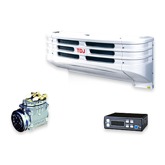
- Page 1 MITSUBISHI TRANSPORT REFRIGERATION UNIT SERVICE MANUAL TDJ300D TDJ430D '99 · TD-S · 001...
- Page 2 Read this manual thoroughly before using to ensure quick and waste-less servicing and to maintain the performance of the refrigeration unit. • How to read the type TDJ430D - 2 L 2 Indication of power voltage [ 2: DC24V...
-
Page 3: Safety Precautions
Safety Precautions Read the "Safety Precautions" thoroughly before using inspections and maintenance. The precautions described here are classified as " WARNINGS" and " CAUTIONS". Items that could lead to fatalities or serious injuries during inspection and maintenance are listed as " WARNINGS". - Page 4 Contents Characteristics 10.16 Storage temperature sensor (TH) ············ ··········································· Specification 10.17 Td sensor (Td) ········································· ················································ General information 10.18 Controller ················································· 19 ································· 10.19 Drain hose heater (option) ······················· Controller ··············································· 1. Electric wiring diagram ··························· Drive system ··········································· 11.1 Sequence diagram ····································...
- Page 5 1. Characteristics We have developed this refrigeration unit based on our long years of accumulation of refrigeration technique. (1) The refrigeration unit is a compactly arranged and unitized type which can be easily installed and removed because of a nose-mounted type. (2) The refrigeration unit can operate in the range of the outside temperature of -5°C ~ 40°C to keep the inside temperature in the rage of -30°C ~ 25°C.
- Page 6 2. Specification (1) TDJ300D Type TDJ300D - 1L2 TDJ300D - 2L2 Item Ambient temperature °C 0°C 3490 (3000) 3490 (3000) * [2790 (2400)] Return air (kcal/h) temperature -18°C 2150 (1850) 2150 (1850) * [1740 (1500)] Function Cooling Inside air temperature °C -30 ~ 25 Range of...
- Page 7 (2) TDJ430D Type TDJ430D - 1L2 TDJ430D - 2L2 Item Ambient temperature °C 0°C 5000 (4300) 5000 (4300) * [4070 (3500)] Return air (kcal/h) temperature -18°C 2790 (2400) 2790 (2400) * [2210 (1900)] Function Cooling Inside air temperature °C -30 ~ 25...
-
Page 8: Controller
3. General information 3.4 Defroster In order to prevent the evaporator from being covered 3.1 Controller with frost and reducing its cooling effect, the defrost timer (it will be established within three hours before The refrigeration unit employs a new microcomputerized being shipped out from our factory) operates controller which has a character display function, and defrosting. -
Page 9: 4. Name Of Each Component
(4) Motor pack (only for type 2) (a) TDJ300D Discharge Suction Compressor service valve service valve Magnet clutch (b) TDJ430D (5) Power source box (only for type 2) Discharge Suction service valve service valve Limit switch Fuses Alarm indication lamp... -
Page 10: Pre-Operation Inspection
5. Adjustment of test operation 6. Daily operation 5.1 Pre-operation inspection 6.1 Description of operation for the controller Check the seal going through the board of 3 Alarm lamp 2 Defrost switch (red) 2 Defrost indication lamp 4 Digital display refrigeration unit. -
Page 11: Other Operations
6.2 Other operations How to display the fault history 1 Press the display switch and alarm switch together When the refrigeration unit stops (power is supplied), for 4 seconds, and max. 5 faults which have the following operations are ready. occurred will be displayed with the codes in Change of inside-container preset temperature sequence from the newest one. -
Page 12: Operation Of Display Switches
Since the controller is provided with the function Since the controller has the function to (memory function) which memorizes the memorize the temperature which was set during temperatures preset in the refrigeration unit up to last operation of the refrigeration unit, press ... -
Page 13: Inspection Before Loading
The defrost timer (factory-set at every 3 hours at 7. Loading shipment) will automatically work for automatic defrosting. 7.1 Inspection before loading When the delay timer of 1 minute runs out after defrosting is completed, it will be automatically Clean inside of the storage. switched into the cooling operation. -
Page 14: Unloading
180V when the motor is started. • Motor specification The values in ( ) are applicable for TDJ430D. Standard specification 3-phases AC 220V 60Hz, 380V 50/60Hz, 415V 50Hz Make the upper side of the load as flat as can be. -
Page 15: Refrigerant Piping System Diagram
8. Refrigerant piping system 8.1 Refrigerant piping system diagram Multi-function valve Refrigeration unit Discharge hose To vehicle’s compressor Suction hose Accumlator Motor pack (Type 2 only) 8.2 Freezing cycle (Type 2 only) Refrigeration cycle Dual pressure switch Dryer Liquid injection electromagnetic valve Receiver Sight glass Multi-function valve... -
Page 16: Control System
Defrost cycle Refrigeration unit Defrost electromagnetic valve (open) Engine drive type Motor pack Remarks: The figure shows an example of Type 2. Type 1 is not equipped with motor pack and accumulator. Motor dirve type 9. Control system Refrigeration unit Control box Controller Power source... -
Page 17: Compressor
Name Specification Name Specification Model CR2211L-A Weight 7.3kg (include magnet clutch) Lubrication system (TDJ430D) Volume of 110cm /rev Lubricating Diamond Freeze Lubrication oil is supplied forcibly to respective discharge MA32 bearings, pistons, tank shaft pins and shaft seals by Revolution... -
Page 18: Heat Accumulator
When sound is heard, it is defective due to wear of the bearing. If the magnet clutch is defective, replace its assembly. Measuring of air-gap TDJ300D: 0.3 ~ 0.5mm TDJ430D: 0.3 ~ 0.6mm Accumulator – 14 –... -
Page 19: Electromagnetic Valve
10.5 Electromagnetic valve How to determine defective or not defective: Same as defrost electromagnetic valve. Defrost electromagnetic valve Refer to "defrost electromagnetic valve". It is installed in order to flow hot gas into the 10.6 Check valve evaporator side when defrosting. It is installed to prevent the refrigerant from flowing back ward. -
Page 20: Sight Glass
10.8 Sight glass It can judge the circulating amount of refrigerant and existence of water in the refrigerant. Dryer When the dryer is replaced, replace it quickly. Here, when installing the dryer, pay heed to its direction and install it on the unit with the arrow mark aligned to the Sight glass flow of the refrigerant. -
Page 21: Evaporator Fan Motor
10.11 Evaporator fan motor Revolution Electric current Input 2000min 2.92A or less Multi-function valve Note: (1) Since the multi-function valve was factory- set at shipment, don't adjust it at the site. If the adjusting screw is turned, the setting will become disturbed to cause a poor operation. -
Page 22: Defrost Thermostat (Dts)
10.14 Defrost thermostat (DTS) Adjustment is impossible. It detects temperature of the evaporator coil and indicates an end of defrosting. Dual pressure switch Defrost thermostat Judgment whether is proper or not CUT IN 0 ± 3°C [High pressure side] CUT OUT 8 ±... -
Page 23: Controller
Storage temperature sensor Td sensor How to determine defective or not defective How to determine defective or not defective: Measure continuity by removing the connector at Measure the resistance value by removing the the edge of temperature detection. connector. (b) Resistance value at the edge of temperature Resistance value in normal condition detection in normal condition. -
Page 24: 10.19 Drain Hose Heater (Option
• Inside-container temperature • Fault display Displayed on • Inside-container preset temperature the digital display unit. • Operation times • Defrost timer Remarks: As to abnormal indication, refer to page 47. 10.19 Drain hose heater (option) It is electrified when the defrost thermostat is "ON"... -
Page 25: Sequence Diagram
White Blue Violet Brown Gray Green Orange Lg Light green Remarks: Three FM (evaporator fan motor) are provided on TDJ430D. Explanation of mark SYMBOL NAME SYMBOL NAME Temperature setting switch (up) Thermostat relay Temperature setting switch (down) Liquid injection electromagnetic relay... - Page 26 TDJ300D-2L2 Explanation of mark SYMBOL NAME SYMBOL NAME SYMBOL NAME AC power indication lamp Temperature setting switch (up) Thermostat relay OCR operation indication lamp Temperature setting switch (down) Liquid injection electromagnetic relay DOWN Fuse (3A) Alarm switch Evaporator fan motor relay ALARM Fuse (5A) Defrost switch...
- Page 27 TDJ430D-2L2 Explanation of mark SYMBOL NAME SYMBOL NAME SYMBOL NAME AC power indication lamp Temperature setting switch (up) Thermostat relay OCR operation indiction lamp Temperature setting switch (down) Liquid injection electromagnetic relay DOWN Fuse (3A) Alarm switch Evaporator fan motor relay...
-
Page 28: 11.3 Explanation Of Operation
11.3 Explanation of operation (Explanation is made for TDJ300D-2L2) In case of engine drive A Cooling operation 1. Start the engine of a vehicle to be run. 2. Turn the operation switch to "ON". • Operation indication lamp will light. (green) •... - Page 29 B Operation of ON-OFF by thermostat during cooling operation. Remarks: The following shows a diagram being stopped by thermostat. 1. In case a storage temperature drops (thermostat "OFF") to an established temperature • AR (thermostat relay) is dropped out, and MCL (magnet clutch) is disconnected and then the compressor stops.
- Page 30 C Defrost operation 1. When defrost switch has been turned on or defrost timer is operating (the timer is built into the controller and is set in 3 hours for shipment from factory) • Defrost indication lamp lights. (orange) • AR (evaporator fan motor relay) is dropped out, and FM (evaporator fan motor) is disconnected and then evaporator fan motor stops.
- Page 31 D Operation of protection device • AR 1. DPS (Dual pressure switch) operates ···· The unit (condenser fan motor relay) is de- stops. energized, FM (condenser fan motor) is disconnected, and the condenser fan motor High pressure side stops. OFF : 2.94MPa (30.0kgf/cm ON : 2.35MPa (24.0kgf/cm Remarks: (1) When alarm lamp lights, the defects will be shown on the display when...
- Page 32 In case of motor drive Remarks: As the operation of the thermostat and defrost is the same with that of engine drive, refer to page 29 and 30. A Cooling operation Turn on the power. • GL (AC power indication lamp) lights. •...
- Page 33 B Operation of protection device OCR (Overcurrent relay) operates ···· The unit stops. • MS (electromagnetic switch) is dropped out, M (motor) is disconnected and the motor stops. • AR (OCR relay) is energized and RL (OCR operation indication lamp) lights. •...
-
Page 34: Daily Inspection
12. Periodic inspection (12) Check starting and stopping of compressor, magnet clutch and fan by thermostat. Perform the periodic inspection for the items required (13) Cooling operation on the following period. Check display for temperature indication and Write down necessary matters to the check sheet on dropping of temperature. -
Page 35: Monthly Inspection
During transportation, look at the display from 12.5 Bolt tightening table for each section time to time to see if it keeps and established Standard tightening torques for flare nuts. storage temperature. Applicable Tightening torque N·m(kgf·cm) copper pipe 12.3 Monthly inspection ø... - Page 36 12.6 Caution to be taken at the time daily inspection Instruct users to comply with the following items. Item Contents Care to be taken at the time of operation Anticipated defect Disposition (remarks) • Perform this as a daily Check for gas 1.
- Page 37 2. When the storage door is than 30mm. open, stop the unit. opened by circulating wind, cold air in the room will be replaced by outside air, which makes The values in ( )are applicable for the storage temperature TDJ430D. rise. – 37 –...
- Page 38 12.7 Caution to be taken at the time of periodic inspection Item Contents Care to be taken at the time of operation Anticipated defect Disposition (remarks) • Tension of belt between Tension of belt 1. Use tension meter to adjust belt and 1.
- Page 39 Item Contents Care to be taken at the time of operation Anticipated defect Disposition (remarks) • Care to be taken when Parts sold at a 1. Do not use easily parts sold at a market 1. In case of tension pulley 1.
-
Page 40: Daily Inspection
12.8 Check sheet (Installation, test run and periodic inspection) Customer’s Customer signature Model Delivery date Refrigeration unit Serial No. Van maker Inspection interval Inspection date Model Compressor kit Serial No. Inspection company Refrigeration Model unit installation Vehicle company Inspector Serial No. Inspection result Remarks Inspection items... - Page 41 0.5 (5) 0.4 (4) 0.3 (3) 0.2 (2) 0.1 (1) 0 (0) MPa(kgf/cm Return air temperature by condenser °C (Outside air temperature) TDJ430D Compressor revolution 1800min 2.7 (28) Storage 2.5 (26) temperature 0°C 2.4 (24) 2.2 (22) 2.0 (20) 1.8 (18) 1.6 (16)
-
Page 42: 13. Defect And Its Cause
13. Defect and its cause 13.1 Diagnosis of defects on refrigerant system Table of defect and cause of refrigerant system Defect Cause Overcharge of refrigerant Shortage of refrigerant No refrigerant Return air temperature by condenser is too high. Clogging of condenser Return air temperature by condenser is too low. - Page 43 Diagnosis by pressure gauge Standard pressure value [Condenser entrance air temperature] + Saturation High pressure pressure of about 14 ~ 16°C Refrigerant pressure [Cool wind entrance temperature] - Saturation pressure Low pressure of about 20°C With the storage temperature at about 0°C Pressure Main causes Both high and low pressure are too high...
- Page 44 Shortage of refrigeration Cause of defect Disposition (1) Wind does not come out much (a) Evaporator coil is frosted. (a) Change operating time of defrost timer. (Type L only) (b) Operate manual defrosting. (c) It is normal if defrost is operating, but if defrost electromagnetic valve (b) Defrost solenoid valve is operating.
- Page 45 Cause of defect Disposition (d) Refrigerant is excessive. (d) It is a little difficult to determine but tendencies are: 1) High pressure gauge indicates high, that is pressure at operation indicates higher value than high pressure power shown on page 2) No bubble can be seen from sight glass even if compressor is turned at high temperature.
-
Page 46: System
13.2 Charging the refrigerant <R404A> Use the following procedure to charge the refrigerant. (1) Operation procedure Service valve B Multi-function valve Condenser fan motor Service valve A HP take- out tube HP take-out port C Discharge operation Suction operation valve D valve (2) Evacuation 2 Since the multi-function valve is installed on the... - Page 47 13.3 Diagnosis of defects on electric parts Confirmation of trouble with controller ALARM • If the "alarm lamp" lights or flickers, press the "alarm switch" . All errors that are currently occurring will be displayed as symbols on the "digital display". Confirm the state with the operation switch turned ON. •...
- Page 48 How to diagnosis defect by controller indication (The trouble diagnosis is explained for the main example of Type 1.) (a) Diagnosis of defect by the alarm lamp "ON" Remarks: (1) Measure voltage by body ground wire. For checking, press the alarm switch. (2) LB, B and BG show the color of wiring.
- Page 49 2) In case indication on display is Fuse (F ) is broken. Replace fuse (F Is battery voltage measured at Replace controller controller C terminal? Is battery L line between controller and voltage measured at 2nd relay box is broken or contact side of fuse (F of connector is defective.
- Page 50 4) In case indication on display is Check dual Abnormal pressure switch Replace dual pressure switch. (DPS) Normal BY and G lines between DPS Voltage (Battery voltage) and relay box and controller between controller 1 are broken or contact of terminal and ground connector is defective.
- Page 51 indicated on the digital display means the compressor on the engine side, and means the compressor on the motor pack.) • For the voltage of the TD sensor, refer to Page 63. Check • Terminal Nos. of TD sensor Abnormal voltage of Replace Td sensor.
- Page 52 Diagnosis of defect other than abnormal indication (a) In case the unit will not operate even turning the operation switch "ON". Unit will not operate with the operation switch ON. Will operation indication lamp light? Is battery voltage measured at terminals and N Controller is defective.
- Page 53 (b) In case evaporator fan motor will not operate. Evaporator fan motor will not operate. Is battery LW line between FM voltage measured at LW connector and relay box F line of fan motor broken or contact of connector is defective. conector? Is battery voltage measured at...
-
Page 54: System
(c) In case compressor will not operate. Compressor will not operate. Is battery voltage measured at GB line of magnet clutch (engine side) connector? BR line between Is battery controller and relay voltage measured box AR is broken or at BR line of AR contact of connector is coil? defective. - Page 55 (f) Defrost operation 1) In case the unit will not defrost. It will not defrost. Is storage Normal if it will temperature under 0°C? not start defrosting. NO (In case battery voltage) Is 2 terminal of controller 0V? Established value of defrost thermostat Abnormal ON: 0°C (It is not “ON”...
- Page 56 2) In case defrost operation will not recover. Defrost operation will not recover. Abnormal (It will not become “OFF” over 8°C) Check defrost Replace defrost thermostat. thermostat Normal 2 terminal RY line of controller is short-circuited and grounded. 3) In case defrost operation is frequently made. Defrost operation is frequently made.
- Page 57 (g) In case drain hose will freeze. Drain hose will freeze. Refer to page 55, defrost Is defrost operation operation. normally made? Is battery LW line between fuse (F ) and voltage measured at LW drain hose heater is broken of line of drain hose heater contact of connector is connector?
- Page 58 (h) In case of motor drive Only the items different from the previous ones are written here. 1) In case evaporator fan will not turn.································································· Refer to page 53. 2) In case condenser fan will not turn.·································································· Refer to page 54. 3) In case thermostat will not operate.··································································...
- Page 59 7) In case compressor will not turn. Compressor does not run. Is AR or relay excited? BR line, wire breakage or poor Is 24V measured connector contact between at AR coil BR line? controller and relay box (AR Is 0.5V or less measured at Defective controller terminal No.O of...
- Page 60 8) OCR (over-current relay) operation indication lamp lights. OCR operation indication lamp lights. Abnormal Check OCR operation Note: For re-operation push manual reset button. Normal Is 3-phase • Breaker is defective. 220V (60Hz), 380V Are OCR terminals • Power source cord is OCR is defective.
- Page 61 Inspection of controller board (a) Cautionary points for handling the printed-circuit board 1) When taking the board, prevent touching any pattern or part with hand. To take the board, pinch it at both sides with hand. 2) Prevent touching the board with hand which oil or similar sticks to. 3) Prevent applying any load to the parts on the board with hand or similar.
- Page 62 (c) Controller inspecting procedure Power supply line breakage Fuse line breakage: 0V Short circuit from pin M Normal time: Battery voltage Normal: 24V Harness line breakage Not connected. Nomral: Battery voltage Power supply line breakage Short circuit from pin NO Normal: Battery voltage Short circuit to GND: 0V Normal, sensor line...
- Page 63 (d) Storage temperature sensor resistance and voltage as reference Temperature (°C) Resistance (kΩ) Voltage (V) Temperature (°C) Resistance (kΩ) Voltage (V) 26.316 4.187 2.573 1.759 20.155 4.004 2.113 1.543 15.572 3.795 1.746 1.349 12.131 3.564 1.451 1.175 9.524 3.313 1.213 1.022 7.533 3.050...
-
Page 64: 14. Method To Select A Model With
14. Method to select a model with jumper cable (1) The following functions are selectable with the jumper cables on the circuit-printed board. Item Jumper cable No. Description Model selection J11, 12 H, M, L Refrigerant selection J21, 22 R22, HFC-134a, R401B, R404A Heating selection Refrigerant heating: Valid/invalid switch... - Page 65 15. REFRIGERANT SATURATED PRESSURE TABLE (R404A) Saturated pressure kPa (kgf/cm Saturated pressure kPa (kgf/cm Temperature (°C) Temperature (°C) –19.2 (144.0mmHg) 627.6 (6.4) –10.6 (79.5mmHg) 666.9 (6.8) –1.3 (9.8mmHg) 715.9 (7.3) 9.8 (0.1) 764.9 (7.8) 19.6 (0.2) 814.0 (8.3) 29.4 (0.3) 872.3 (8.9) 39.2 (0.4) 921.8 (9.4)
-
Page 66: System
16. INSTALLATION PROCEDURE 16.1 Cautionary points during installation Be absolutely sure to keep dust and moisture from (13) Route the high-/low-pressure hoses with care to entering the piping of the refrigeration unit. consider the three-dimensional dislocation of the compressor as 15mm in each direction in order to Carry out the connecting of separate type of piping prevent them from interfering with each other. - Page 67 16.2 Cautionary and requested points during installation Item Explanation Precaution for service Possible failure Corrective action (Remarks) • When installing the Direct coupled 1. Adjust the misalignment to 0.5 degrees 1. Abnormal wear of V belt 1. Recondition, adjust or type unit compressor with the or less.
- Page 68 Item Explanation Precaution for service Possible failure Corrective action (Remarks) • The pipe, harness clamp Clamp 1. When the screw hole for the clamp is 1. Unless blocked by sealer, 1. No remedy for the body mounting for or pipe cover is fastened drilled to the body, be sure to coat sealer.
- Page 69 Item Explanation Precaution for service Possible failure Corrective action (Remarks) 7. When wiring is made under the floor or 7. Defective contact due to at a place where rain water splashes, set generation of rust and up a trap on the straight line so as to broken wire.
- Page 70 Item Explanation Precaution for service Possible failure Corrective action (Remarks) • The installation direction Installation In case of CR2211L-A 1. Compressor may be 1. If the direction 4 in the direction of of the compressor is damaged since liquid is left is inevitably applied, compressor restricted.
- Page 71 1. This installation drawing is for models TDJ300D and TDJ430D. 2. Drawing on the upper shows illustration layout of models TDJ300D and TDJ430D. 3. The fabricated or renovated structure of the van must be designed for the installation of refrigeration units.
- Page 72 Cautions for safety installation Caution for safety installation WARNING Before installing the refrigeration unit, read first this installation manual and follow strictly the instructions to prevent any trouble or accident. 1. Preparations for the vehicle (1) Use stoppers for front and rear wheels to prevent the vehicle from forward and backward movement during installation.
- Page 73 3. Test operations procedure (1) Use stoppers for front and rear wheels to prevent the vehicle from forward and backward movement during test operation. Furthermore, the parking brake must be activated. If failed to do so. Accident may occur causing injuries to worker or operator due to mis-operation.
- Page 74 Outline drawing (a) Compressor 1) TDJ300D Unit: mm Compressor 7.3kg 2) TDJ430D Compressor 13.5kg – 74 –...
- Page 75 (b) Refrigeration unit Note: Mark indicates the center of gravity. Unit: mm Refrigeration unit TDJ300D: 67kg, TDJ430D: 72kg (c) Controller Controller 0.5kg – 75 –...
- Page 76 Note: Mark indicates the center of gravity. Unit: mm (d) Motor pack 1) TDJ300D 2) TDJ430D Motor pack Motor pack 54kg 85kg (e) Power source box 2) TDJ430D 1) TDJ300D Power source box Power source box 17kg 19kg – 76 –...
- Page 77 The fabricated and renovated structure of the van must be designed for the installation of refrigeration unit, weighing 72kg for TDJ430D & 67kg for TDJ300D. (Must withstand vibration shock of 7G). The bolt must be securely tightened. Position of mounting hole and bolt holes for the unit Mounting hole and bolt holes for the unit must restrict heat transfer.
- Page 78 4. If the exhaust pipe port of the car muffler is present in front of the motor pack and accumulator, the unit can not show its performance. Therefore, dislocate the exhaust pipe to be positioned behind the motor pack and accumulator. Motor pack Power source box Model TDJ300D TDJ430D – 78 –...
- Page 79 Piping installation (a) In case of type 1 Notes: 1. For charging mass of refrigerant refer to note 2 of next page. 2. Connection of pipings must be gauged. 3. It must be free from any foreign matters to prevent clogging of valves, malfunction of solenoid valves and damage of compressor.
- Page 80 Type 2 R404A TDJ300D TDJ430D R404A 3. Compressor outlet and inlet pipe should be fixed because water absorption power of oil is high. 4. Pipe should be fixed lastly the same as compressor pipe. Because dryer and sight glass are already installed.
- Page 81 (c) Piping installation 1) Type 1 piping installation 2) Type 2 piping installation – 81 –...
- Page 82 Wiring connection Notes: 1. Remove the negative (-) terminal of the battery. 2. Never interchange battery connections otherwise it will burn or damage the electrical parts. 3. Remove the painting on the frame before connecting the ground terminal. 4. Each wiring should be routed along with the existing harness or piping. 5.
- Page 83 Installation of controller at inside panel (option) (a) Applicable for Mitsubishi FK, FM vehicles of Model '92 and following Notes: 1. This installation drawing of controller is for Mitsubishi FK, FM which is available after '92 model. 2. Installation procedure (1) Remove the center panel.
- Page 84 (b) Applicable for Mitsubishi FE, FG vehicles sold since November, '93 Notes: 1. This installation drawing of controller is for Mitsubishi FE, FG which is available after november of '93. 2. Installation procedure (1) Remove the instrument vessel. (2) Remove the radio & accessory box with inside panel bracket.
- Page 85 Cautions for electric wiring The following are procedures on repair and addition of wiring for fire prevention (a) General guidelines on addition and repair of wiring: See JIS C3406 (for low voltage wiring for automobile), JASO 0608 (heat resistance low voltage wiring for automobile), JIS C2336 (insulation tape for wiring) vinyl tape or equivalent.
- Page 86 3 Caution on welding works Battery terminals must be detached before welding. Do not position the ground terminal near the electronic parts or the electronic parts lie between it and the area to be weld to prevent damage. Even the parts have switches. But still must follow the guidelines below. 1) Detached the battery terminal 2) Position the ground terminal near the object to be weld.
- Page 87 (11) Part list No. Required Item Name Part No. TDJ300D TDJ430D Remarks ACA201A304 CR2318LWR (TCP18H2) Compressor assembly ACA200A009A CR2211L-A (TCP11F2) CSA272C004 TCP18C2-KT1 Either 1 Clutch, EM 1 piece TSJ272C042 TCP18C2-KT2 B070B10 × 035 M10 × 35 B070B10 × 025 M10 ×...
- Page 88 No. Required Item Name Part No. TDJ300D TDJ430D Remarks W220R10 M10 (Use those used in the packaging) Washer, spring W220G10 For M10 (SUS) SSA937D045A Band SSA937D045B Hose, drain TSJ423A015 Port, drain TSJ423J008 Insulation SSA151B459CA L = 2m TSJ937A013F ø12 TSJ937A013L ø20...
- Page 89 No. Required Item Name Part No. TDJ300D TDJ430D Remarks Plug SSA566B011 E011 × 02F003 Terminal SSA562D003C TJD504A014C None Power box ~ relay box (5.5m) Harness assembly TJD504A020A None None Td sensor (5m) TJF504A079 Power box ~ relay box (9.3m) B010A10 × 025 M10 ×...
- Page 90 No. Required Item Name Part No. TDJ300D TDJ430D Remarks SSA937A002R ø20 TSJ937A012B ø6 Clamp TSJ937A013F ø12 TSJ937A013L ø20 TSJ937A013N ø25 TJF351A007 Accumulator assy TJF351A007A Bracket TSJ116A001B Note: When procuring the part, be sure to refer to Parts List separately issued.
- Page 91 AIR-CONDITIONING & REFRIGERATION MACHINERY WORKS AUTOMOTIVE & COLD CHAIN MACHINERY BUSINESS SECTION 3-1, Asahimachi, Nishibiwajima-cho, Nishikasugai-gun, Aichi-pref., 452-8561, Japan Phone : (052) 503-9209 : (052) 503-2638 No.079 (1.3A) R...
Need help?
Do you have a question about the TDJ430D and is the answer not in the manual?
Questions and answers