Table of Contents
Advertisement
Quick Links
Advertisement
Table of Contents

Related Manuals for SALUDA MEDICAL Evoke SCS


Summary of Contents for SALUDA MEDICAL Evoke SCS
- Page 1 Evoke® SCS System Clinical Manual Evoke® SCS System Clinical Manual Use of the Evoke Clinical Interface (CI) and Clinical Programming Application (CPA) with the Evoke Clinical System Transceiver (CST) for programming the Evoke SCS System CLIN-UMAN-005175 Revision: 9.00 Page 1 of 101...
-
Page 2: Table Of Contents
Evoke® SCS System Clinical Manual Table of Contents DESCRIPTION ........................5 ECAP- SCS ............5 HE CONCEPT OF CONTROLLED CLOSED LOOP ....................... 5 TIMULATION EATURES ....................6 EASUREMENT EATURES ......................8 YSTEM OMPONENTS INDICATION FOR USE ..................... 10 CONTRAINDICATIONS ....................10 SAFETY INFORMATION .................... - Page 3 Evoke® SCS System Clinical Manual ..................... 61 LECTRODE SELECTION MODES ........................62 MENU ......................65 AVIGATION MENU ......................65 ETTINGS SCREEN ....................68 LERT AND ERROR DISPLAY INTRA-OPERATIVE PROGRAMMING WITH THE CI ............70 CLS ..............70 ONNECT THE INTRAOPERATIVE CABLE TO THE E ..................
- Page 4 Evoke® SCS System Clinical Manual Trademarks Saluda, Evoke, and the Saluda Medical logo are registered trademarks of Saluda Medical Pty Ltd. Copyright © 2022 Saluda Medical Pty Ltd, Sydney, Australia. All rights reserved. Refer to the Evoke SCS System Surgical Guide for: •...
-
Page 5: Description
Evoke® SCS System Clinical Manual 1 Description The Saluda® Medical Evoke® SCS System is a Spinal Cord Stimulation (SCS) system that incorporates ECAP-controlled closed-loop stimulation for the management of chronic, intractable pain. The Evoke System measures evoked compound action potentials (ECAPs) and may be programmed to deliver either ECAP-controlled closed-loop SCS or fixed-output open- loop SCS. -
Page 6: Measurement Features
(pulse width, frequency, interphase gap and inter-stimulus interval). 1.3 Measurement Features The Evoke System supports the following types of measurements and data analysis. Refer to the Evoke SCS System Clinical Data Viewer User Manual for additional information on data analysis. 1.3.1... - Page 7 Evoke® SCS System Clinical Manual 1.3.4 Detection of late response Late responses are neural responses resulting from dorsal root activation. Late responses have longer latency than ECAPs and they do not propagate along the spinal cord. They can be viewed in the CPA during a programming session or reviewed later in the CDV.
-
Page 8: System Components
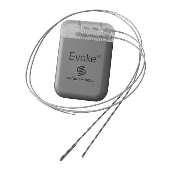
Evoke® SCS System Clinical Manual 1.4 System Components 1.4.1 Evoke Closed-Loop Stimulator (CLS) Ref No. 3002 The Evoke Closed-Loop Stimulator (CLS) is a totally implanted spinal cord stimulator that connects to the 12C Percutaneous Leads and is implanted under the skin for long-term therapy. The CLS delivers either closed-loop or open-loop stimulation through the leads and measures the neural response to stimulation. - Page 9 Evoke® SCS System Clinical Manual The Evoke Intraoperative Cable allows the surgeon to connect the eCLS to the implanted leads for intra-operative testing. 1.4.7 Evoke Patient Controller (EPC) Ref No. 3040 The Evoke Patient Controller (EPC) allows the patient to control their therapy and actively monitors the stimulator battery status and other elements of the system.
-
Page 10: Indication For Use
Evoke® SCS System Clinical Manual 2 Indication for use The Saluda Medical Evoke SCS System is indicated as an aid in the management of chronic intractable pain of the trunk and/or limbs, including unilateral or bilateral pain associated with the following: failed back surgery syndrome, intractable low back pain and leg pain. - Page 11 4.1.6 Clinical staff training Clinical staff using the CI/CST to program the Evoke SCS System must be adequately trained in the programming of SCS systems generally. Additionally, clinical staff programming the Evoke SCS System should have read the instructions within this manual. A poor understanding of the programming of SCS systems generally, and the Evoke system specifically, could cause unpleasant or painful stimuli for patients.
-
Page 12: Introduction
Clinical Programming Application (CPA) that enables programming of either the Evoke eCLS or CLS. Note: Login password for the CI will be provided by Saluda Medical representatives and cannot be changed. All potential CI operators should be made aware of this password. -
Page 13: Clinical Interface - General Programming Using The Cpa
Evoke® SCS System Clinical Manual 6 Clinical Interface – General programming using the CPA 6.1 Connecting the CI to the CST and eCLS/CLS To program and download data from the eCLS or CLS, communication must first be established. The CST connects to the CI to communicate using a radio signal transmitted to the eCLS or CLS. 1. - Page 14 Caution: Before connecting the CPA to the stimulator, ensure that you have a magnet and paired EPC (see Section 13.1) available at all times during the programming session in case they are needed to stop stimulation (refer to the Evoke SCS System User Manual).
-
Page 15: Set Stimulator Time
Evoke® SCS System Clinical Manual Visit Name Connect to dropdown menu Implant button Figure 6.3: Location of the Visit Name dropdown menu and Connect to Implant button. 7. Touch the stimulator serial number that you wish to connect to. 8. The CPA will connect to the stimulator and retrieve any patient data and programs. Note: Depending on the amount of data saved on the device this could take several minutes. -
Page 16: Check Stimulator Battery Voltage
(3.25 to 4.10 V; Figure 6.4). If the battery voltage is low (<25 % full) the bar will be red. Refer to the Evoke SCS System User Manual for instructions on charging the CLS battery or Section 11.4 for charging the eCLS battery. - Page 17 Evoke® SCS System Clinical Manual Figure 6.6: CLS Icon with Patient ID and Done button. Note: If you do not touch the Done button, the Patient ID will be automatically updated in the stimulator when you start stimulation. 4. Navigate to the settings page by opening the navigation menu and touching Settings (see Figure 6.7).
-
Page 18: Measure Electrode Impedances
Evoke® SCS System Clinical Manual Patient Zone dropdown menu Figure 6.8: Settings menu with Patient Zone dropdown menu highlighted. 6.5 Measure electrode impedances Measure the electrode impedances to determine if all connections are intact between leads, any lead adapters, and the stimulator. 1. -
Page 19: Set Up Lead Orientation
Evoke® SCS System Clinical Manual Figure 6.9: Impedances displayed on the 24 electrodes and CLS case (E25). 3. An electrode with a cross through it has high impedance (> 4000 Ω) and may be disconnected. A disconnected electrode shows an impedance of ∞ and cannot be used for stimulation. -
Page 20: Programming Overview
Evoke® SCS System Clinical Manual Figure 6.10: You can drag the leads up, down or switch sides. 6.7 Programming overview 1. Test stimulation from several electrodes (see Section 6.8 and 6.9) and ask the patient to report where they feel paresthesia. 2. -
Page 21: Start And Stop Stimulation With Closed-Loop Disabled
Evoke® SCS System Clinical Manual 5. The CPA will automatically select the stimulation , return measurement and reference electrodes for you. • You may steer the current between stimulation electrodes (see Section 7.3). • You can also manually change the electrode configuration (see Section 8.3), e.g. if you want to move electrodes or add additional stimulation or return electrodes. - Page 22 Evoke® SCS System Clinical Manual Section 8.1). The icon will change to show the Electrode Display icon (Figure 6.12). Changes made to the stimulation settings will affect the stimulation current control bar on the right (refer to Figure 6.13 for more details). Start Stimulation arrow...
-
Page 23: Set Up Ecap Measurement
Evoke® SCS System Clinical Manual A: Up arrow B: Maximum current C: Current scale D: Current increment scale E: Desired current level F: Current increment G: Down arrow Figure 6.13: Features of the stimulation current control. 6.9.1 Stop Touch the Stop button to stop stimulation at any time. - Page 24 Evoke® SCS System Clinical Manual Figure 6.14: A) ECAP amplitude and current rolling plot; B) ECAP display; C) ECAP measurement and closed-loop settings icon location. When selected the icon changes to the Electrode Display icon; D) Measurement electrode scan window; E) ECAP measurement and closed-loop settings menu;...
- Page 25 Evoke® SCS System Clinical Manual Average ECAP Display mode estimates Zoom out (Y-scale) Correlation filter used to measure (white) Sampling period Recommended measurement settings Zoom in (Y-scale) Measurement settings in use Figure 6.15: A) ECAP display for the selected measurement electrode configuration (orange) and 3 other configurations (green, blue and red).
- Page 26 Evoke® SCS System Clinical Manual 6. Touch Apply to set the optimal Processing Offset . The open circle on the plot is the recommended offset (peak of plot), while the black line is the offset setting in use. 7. Touch Apply to set the optimal Filter Frequency .
- Page 27 Evoke® SCS System Clinical Manual Figure 6.17: The ECAP measurement (top) and current (bottom) rolling plot. 6.10.1 ECAP measurement options There are four measurement setup options in the Measurement and Feedback settings menu (see Section 8.2): 1. ECAP Raw Data Logged The ECAP signal is recorded and displayed in the ECAP display, but the system does not measure the amplitude of the ECAP.
- Page 28 Evoke® SCS System Clinical Manual The ECAP amplitude is measured from the peak-to-peak amplitude of the ECAP signal within the Processing Period (see Section 8.2) and there will be no recommended measurement settings (see Figure 6.18). For this option, closed-loop may be enabled, and stimulation frequency is available up to 250Hz.
-
Page 29: Set Up Closed-Loop Stimulation
Evoke® SCS System Clinical Manual 3. ECAP Minimum The minimum ECAP amplitude recorded by the stimulator. The default setting is -20 µV. Consider changing this to a value less than the ECAP amplitudes measured during collection of the activation plot and posture testing (see Section 12.5) to ensure that ECAP amplitude is recorded over the full range of activation 4. -
Page 30: Set Appropriate Limits And Increments
Evoke® SCS System Clinical Manual signal quality by adjusting the ECAP measurement settings (see Section 6.10) and/or adjusting the stimulation settings (see Section 6.8). Estimated slope of Activation Plot (gray line) Measured Sensitivity Point where ECAP measurement starts to increase (ECAP threshold) ECAP measurement axis... -
Page 31: Enable Closed-Loop Stimulation
Evoke® SCS System Clinical Manual Table 6.1: Guidelines for setting appropriate limits and increments for stimulation current and ECAP target. Parameter Guideline Maximum Current Set to the first available value !1.5 x stimulation current at the Limit (mA) Maximum activation plot level, measured while the patient is in the (see Section 8.1) sitting posture (see Section 7.6). - Page 32 Evoke® SCS System Clinical Manual variability. b. If the measured sensitivity is low (near 10 µV, see Section 6.11) and the stimulation frequency is low (e.g. 10-20 Hz), try increasing the stimulation frequency (see Section 8.1) to reduce the variability. If you change the stimulation frequency, you will need to check the ECAP measurement and re- measure the activation plot (repeat the steps from Section 6.10 onwards).
-
Page 33: Start And Stop Stimulation With Closed-Loop Enabled
Evoke® SCS System Clinical Manual Figure 6.21: Rolling plot (with closed-loop enabled) while the patient is transitioning from sitting (earlier in time, to the left, where current is higher) to supine (later in time, to the right, where current is lower). 6.14 Start and Stop stimulation with closed-loop enabled Closed-loop stimulation may be changed using the ECAP amplitude bar (Figure 6.22). -
Page 34: Save A Program To The Stimulator
Evoke® SCS System Clinical Manual A: Up arrow / Start CL stimulation B: Average ECAP measurement C: Maximum ECAP target D: Desired target value / level E: ECAP measurement scale F: ECAP measurement G: Target increment scale / value H: Minimum ECAP target I: Patient sensitivity setting J: Down arrow Figure 6.22: Features of the ECAP amplitude bar. - Page 35 Evoke® SCS System Clinical Manual to that program slot appear in the box. 2. Select electrodes and change settings as required. Note: If a program on the CPA has not been run on the stimulator (such as a new program, or one that has been modified), it will be shown in red in the corresponding program slot.
-
Page 36: Create A New Program Or Use Programming Features And Settings
Evoke® SCS System Clinical Manual Caution: The programs in the save slots will only be saved locally on the CI you use to program the patient. If you use more than one CI in your clinic, the programs in the save slots will not be available on any other CI. -
Page 37: Clinical Interface - Programming Features
Evoke® SCS System Clinical Manual 7 Clinical Interface – Programming features 7.1 Stimulation Waveform Each stimulation waveform consists of constant current, actively charge-balanced, pulses. The output current is automatically controlled when closed-loop is enabled, and set to a fixed level when closed-loop is disabled. -
Page 38: Clearcap
Evoke® SCS System Clinical Manual 7.1.3 Pulse width With a biphasic pulse, the pulse width sets the duration of each phase. With a triphasic pulse, the pulse width sets the duration of the second phase, which is equal to the sum of the durations of the first and third phase. -
Page 39: Current Steering
Evoke® SCS System Clinical Manual • ECAP amplitude variability (refer to rolling plot in Figure 6.14A) should be unchanged or reduced with ClearCAP enabled. • Criteria described in Sections 6.10 to 6.14 are met with ClearCAP enabled. Note: If the criteria above cannot be met, ClearCAP should be disabled for the current program configuration. -
Page 40: Measurement Electrode Scan
Evoke® SCS System Clinical Manual Figure 7.3: Current steering: 50:50 (%) on the left and 70:30 (%) on the right. 7.4 Measurement electrode scan The measurement electrode scan allows ECAPs from multiple electrode configurations to be displayed on the ECAP display (7.4.1.1) at the same time. It is intended to assist in optimizing the choice of measurement electrodes and settings. - Page 41 Evoke® SCS System Clinical Manual Figure 7.4: Measurement electrode scan window showing: A) 4 electrode configurations, SQI values and Settings button; B) Scan stopped; C) ‘-’ indicates not enough stimuli to calculate SQI, grayed slots indicates that the scan is disabled; D) SQI = 0% indicates no ECAP has been detected, blank slot indicates there is no valid scan configuration available;...
- Page 42 Evoke® SCS System Clinical Manual A) Raw • latest recorded signal (light line, e.g. • average recorded signal (dark line, e.g. • average artifact estimate (thin line, e.g. B) Scrubbed (simple) • average ECAP estimate (dark line, e.g. C) Scrubbed (detailed) •...
- Page 43 Evoke® SCS System Clinical Manual best ECAP estimate possible. The SQI may be compared across different measurement configurations to determine the optimal settings for ECAP measurement. Note: If an ECAP is present in the ECAP signal, the SQI value may gradually increase with time (i.e.
- Page 44 Evoke® SCS System Clinical Manual 7.4.3 Measurement electrode scan settings 1. Touch the Settings button to change the measurement electrode scan settings. Button Action Clear SQI Clear the SQI values and restart the SQI calculations. The SQI will be displayed as ‘-’ until ECAPs are received. Stop / Start Scan Stop or Start the measurement electrode scan while stimulation is running.
-
Page 45: Interleaved Stimulation
Evoke® SCS System Clinical Manual Optimal Fixed Reference Fixed Fixed Distance Measurement -E25 -E12 -E12 -E12 -E12 -E10 -E11 -E10 -E11 Figure 7.6: Examples of Measurement Electrode Scan position configuration methods when the stimulation electrode is at E2. 7.4.4 Measurement electrode scan enabled on device connection The measurement electrode scan is enabled by default when you connect to a stimulator. - Page 46 Evoke® SCS System Clinical Manual Stimulation Sets Ungroup/ Group Sets Enable/ Disable Set Figure 7.7: Location of controls related to interleaved stimulation in the CPA. 7.5.1 Set up interleaved stimulation To set up multiple stimulation sets in a program: 1. Select a program, and the desired stimulation set (A, B, C or D). a.
- Page 47 Evoke® SCS System Clinical Manual 5. Repeat Step 4 for each remaining stimulation set in the program until all have been set to the threshold level. 6. Set the stimulation sets to run in Grouped mode ( ),and increase (all stimulation sets) to the patient preferred level (Figure 7.8).
- Page 48 Evoke® SCS System Clinical Manual Note: The stimulation sets that are still enabled will continue to increase at the previous ratio (Figure 7.9). Note: If a stimulation set is disabled ( ) its ratio will be set to 0 and it will need to be reconfigured (refer to Section 7.5.3).
-
Page 49: Activation Plot Levels
Evoke® SCS System Clinical Manual Original ratios, stimulation set C selected Stimulation set C ratio lowered Figure 7.10: (Left) A program with 4 stimulation sets in Ungrouped mode with stimulation set C selected. (Right) The ratio for stimulation set C has been reduced while the others remain the same. -
Page 50: Data Files
CI in the ‘SaludaData’ folder, or the ‘NonSync’ folder if the patient has not consented for data to be transmitted to Saluda Medical (see Section 7.9). The data is organized in folders named with the Patient Zone and Patient ID, and contains folders named with the date, stimulator serial number and Visit Name. -
Page 51: Neurophysiological Measurements
Evoke® SCS System Clinical Manual To review the data files refer to the Evoke SCS System Clinical Data Viewer User Manual. 7.7.1 Notes During a programming session the data may be annotated with a time-stamped note. 1. Type a text note in the Notes field (see Figure 6.2). - Page 52 Evoke® SCS System Clinical Manual Neurophysiological Measurement menu Figure 7.12 Location of controls to initiate neurophysiological measurements. 7.8.1 Neurophysiological measurement menu Collect data to estimate the Perform a Chronaxie and chronaxie and rheobase of the Rheobase Measurement stimulated neurons. See Section 7.8.2.
- Page 53 Evoke® SCS System Clinical Manual 7.8.2 Chronaxie and rheobase measurement Collect data to estimate the chronaxie and rheobase of the stimulated neurons. The chronaxie and cheobase measurement involves automatically increasing then decreasing current at different pulse widths. Stimulation may be stopped at any time with the Stop button To perform a chronaxie and rheobase measurement: 1.
- Page 54 14. Touch the Cancel button to close the neurophysiological measurements menu. 15. Use the CDV to calculate chronaxie and rheobase using the data that was collected. Refer to Evoke SCS System Clinical Data Viewer User Manual for instructions. 7.8.3 Conduction velocity measurement Collect data to estimate the velocity at which elicited neural responses travel up or down the spinal cord.
- Page 55 12. Touch the Cancel button to close the neurophysiological measurements menu. 13. Use the CDV to calculate conduction velocity using the data that was collected. Refer to Evoke SCS System Clinical Data Viewer User Manual for instructions. 7.8.4 Lead offset measurement Collect data to automatically estimate the vertical alignment of the implanted leads.
- Page 56 Evoke® SCS System Clinical Manual To estimate the lead offset: 1. Touch Lead Offset from the neurophysiological measurement menu. Note: Ensure that only the applied stimulation set is enabled before continuing (see Section 7.5). The lead offset test will save the stimulation set parameters before the test and restore them after the test.
-
Page 57: Additional Impedance Measurements
Note: This will take approximately 8 minutes. • Load from file: Measure the impedances between electrodes specified in a ‘.csv’ file. Note: The file will be provided by Saluda Medical Field Clinical Engineer (FCE) if required. Note: The impedance measurement can be cancelled by pressing the ‘Cancel’ button below the CLS Menu once measurement has started. - Page 58 Evoke® SCS System Clinical Manual Figure 7.15: Example Consent question. Note: The Patient ID on the CLS Programming page will be in green text if the consent answer is Yes (e.g. )and orange if the consent answer is No (e.g. 4.
-
Page 59: Clinical Interface - Settings Guide
Evoke® SCS System Clinical Manual 8 Clinical Interface – Settings guide 8.1 Stimulation settings menu Stimulation Set Stimulation set slots, labeled A, B, C or D. selection Empty slots represent unused stimulation sets. Stim Set Parameters Set Defaults Set stimulation settings to default values for the selected stimulation set Pulse Width 20 –... -
Page 60: Measurement And Feedback Settings Menu
Evoke® SCS System Clinical Manual 8.2 Measurement and feedback settings menu Set Defaults Set Measurement and Feedback Settings to Filter (+/-) default values Measurement Setup * Raw data, Filter (+), Filter (-), Amplitude Note: For Raw data, Closed-loop is disabled and the settings for Processing Offset, Processing Period, Patient Sensitivity, and ECAP Target Increment are disabled. -
Page 61: Electrode Selection Modes
Evoke® SCS System Clinical Manual 8.3 Electrode selection modes You can configure electrodes automatically or manually by touching the Electrode Selection Mode icon when stimulation is turned off. The selection mode toggles between: You select the stimulation electrode and all other electrodes are chosen automatically: •... -
Page 62: Cls Menu
Evoke® SCS System Clinical Manual 8.4 CLS menu The CLS icon displays the status of the stimulator. Connected to CLS Connected to eCLS Demo stimulator Stimulator is disconnected CLS time is not synchronized CST is disconnected Stimulator battery voltage indicator Electrode disconnected Stimulation is on CLS battery is being charged... - Page 63 Evoke® SCS System Clinical Manual Touch the CLS icon for additional CLS and eCLS functions. Disconnect Disconnect CPA from stimulator. Connect to … Search and connect CPA to stimulator. Implant Run in Demonstration mode. Normal Connect to … operation connected to a simulated Demo (demo) stimulator.
- Page 64 Evoke® SCS System Clinical Manual Enable or disable the ability use the EPC to enable/disable CL stimulation. When EPC Mode Change is Enabled, CL can be enabled/disabled from the EPC. When EPC Mode Change is Disabled, CL cannnot be enabled/disabled from the EPC.
-
Page 65: Navigation Menu
Evoke® SCS System Clinical Manual 8.5 Navigation menu Touch the navigation menu icon for additional CPA functions. Close navigation menu Close CPA – stimulation will continue if Quit Go to the patient survey screen (see Survey Section 7.9) Go to the settings screen (see Section Settings 8.6) Programming... - Page 66 Evoke® SCS System Clinical Manual Navigation Menu Open the navigation menu. Stop Stop stimulation Engineering Used by Saluda Medical staff to obtain Information device related information Restore devices to default factory settings. For use by Saluda Medical Field Factory Reset Clinical Engineer (FCE).
- Page 67 Evoke® SCS System Clinical Manual ECAP Target Max Only applies when connected to CPA. Ramp Rate 1 – 200 μV/s ECAP Minimum Minimum ECAP amplitude recorded by the stimulator (-1000 – 1000 μV) ECAP Target Minimum ECAP Target that can be set Minimum with the CPA or EPC (-1000 –...
-
Page 68: Alert And Error Display
Description Clipping count Reference clock error count Magnet stop count (see Evoke SCS System User Manual) Current at maximum count If present, then Usage Log did not download or there was an error If present, then Therapy Log did not download or there was an error CLIN-UMAN-005175 Revision: 9.00... - Page 69 A Safe Mode error is also indicated with the Contact Clinician indicator on the patient EPC and Charger (see Evoke SCS System User Manual). If a Safe Mode error is encountered: 1. Use the CPA to reset the CLS or eCLS out of Safe Mode (see Soft Reset in Section 8.4).
-
Page 70: Intra-Operative Programming With The Ci
Following lead placement based on required anatomical location, the surgeon connects the leads to the intraoperative cable inside the sterile field (see Evoke SCS System Surgical Guide for details). The surgeon passes the proximal end of the intraoperative cable out of the sterile field to the programming clinician. -
Page 71: Confirm Optimal Lead Placement
Evoke® SCS System Clinical Manual Figure 9.1: Connect the proximal end of the intraoperative cable to the eCLS. Port 2 (electrodes 13–24) is shown here. Port 1 (electrodes 1-12) is on the opposite side of the eCLS. 9.2 Confirm optimal lead placement Physicians may have a preference on the method to confirm optimal lead placement in the operating room. -
Page 72: Confirm Cls Connection
Evoke® SCS System Clinical Manual percutaneous lead(s) to a new position. • Verify ECAP measurement after changing settings or moving the percutaneous lead(s). 5. When satisfied with the lead placement, turn stimulation off and disconnect the eCLS from the intraoperative cable. 6. -
Page 73: Post-Operative Programming Procedures
Evoke® SCS System Clinical Manual • If any electrode has an impedance measurement that is greater than 4000Ω, check all the connections. • Check impedances after each reconnection. 3. The surgeon tightens the set-screw on the CLS header when satisfied that there is a proper connection. - Page 74 Evoke® SCS System Clinical Manual Lead Adapter Plug Figure 11.1: A) The lead adapter. B) Placing the tip of the proximal connector into the lead adapter slot. 2. Push the lead down into the slot completely using your finger (Figure 11.2), so that the lead is flush with the top of the slot.
-
Page 75: Connect The Lead Adapter To The Ecls
Evoke® SCS System Clinical Manual Figure 11.3: Placing the top cover over the lead and sliding onto lead adapter until it clips into place. 11.2 Connect the lead adapter to the eCLS Figure 11.4: Connecting the lead adapter to the eCLS. Port 2 (electrodes 13–24) is shown here. Port 1 (electrodes 1-12) is on the opposite side of the eCLS. -
Page 76: Place The Ecls Into The Case
Evoke® SCS System Clinical Manual 11.3 Place the eCLS into the case 1. Ensure that a fully charged battery is inserted in the eCLS (see Section 11.4; Figure 11.5). 2. Open the eCLS case with the lead exits pointing up. Place the eCLS into the orange seal side of the case, with the eCLS battery facing up and the leads pointing up over the lead exits (see Figure 11.5). -
Page 77: Secure The Ecls For The Trial Stimulation Period
1. The eCLS may be worn by the patient for the duration of the trial stimulation period in either of two ways: a. In a pouch (see the Accessory Belt section in the Evoke SCS System User Manual), b. Placed on a dressing and taped to the skin by the clinician. -
Page 78: Reference Clock Error
Evoke® SCS System Clinical Manual stimulation intensity using the EPC. Closed-loop is automatically re-enabled, without interrupting stimulation, once the ECAP signal is detected. The system determines an ECAP has been detected when the ECAP amplitude reaches half the original target value. If OOC occurs when closed-loop is disabled with electrodes connected, then stimulation will continue. -
Page 79: Evoke Patient Controller
ECAP amplifier gain to Low and stimulation continues. 13 Evoke Patient Controller Refer to the Evoke SCS System User Manual for full details on use of the Evoke Patient Controller (EPC). 13.1 Pair EPC to stimulator To enable the EPC to be used with an eCLS or CLS it must first be paired with that stimulator. -
Page 80: Evoke Charger
14 Evoke Charger Refer to the Evoke SCS System User Manual for full details on use of the Evoke Charger to charge the CLS. If the stimulator is being charged when connected to the CPA, an indication is displayed on the CLS icon next to the CLS battery voltage indicator. -
Page 81: Patient Education And Id Card
Note: During charging, ECAP measurements may be distorted by the charging field. 15 Patient education and ID card Educate the patient on the use of their EPC and Charger (if applicable) using the Evoke SCS System User Manual. All patients should be supplied with a Patient ID card for the clinician to complete. -
Page 82: Maintenance Of The Evoke Ci And Evoke Cst
The CST is not expected to be in direct contact with patients but should still be periodically cleaned. The CST can be cleaned with a soft cloth dampened with a mild disinfectant or alcohol. Refer to the Evoke SCS System User Manual for advice on the maintenance of additional components of the Evoke SCS System. -
Page 83: Disposal Of Devices
17 Disposal of devices DO NOT dispose of the CI or the CST in municipal waste facilities. Please return any items to Saluda Medical via your Saluda Medical representative for proper disposal. 18 Troubleshooting Table 18.1: Troubleshooting. - Page 84 Evoke® SCS System Clinical Manual Issue Possible Explanation Corrective Action Programming Icon may have been Using the CI search function, locate software (Evoke CPA) moved or deleted. and select the 'Evoke CPA'. The icon is not visible. program should start. If this procedure fails, please call your Saluda Representative.
- Page 85 Evoke® SCS System Clinical Manual Issue Possible Explanation Corrective Action Communication may be Move CST closer to device. Ensure no disrupted. EMI from other devices. Software freezes or Other applications open. Re-start software. Close other has very slow applications that are running. response.
- Page 86 Evoke® SCS System Clinical Manual Issue Possible Explanation Corrective Action Clipping causes Recording Electrode is Check electrode connectivity with an stimulation to stop. disconnected. impedance check. Input to amplifier is too Switch to low gain mode. large. Check the impedances and the connections to the stimulator if using an eCLS.
-
Page 87: Package Contents
(Ref No.: 3004) 20 Technical Specifications 20.1 Device Specifications Refer to the Evoke SCS System User Manual and Evoke SCS System Surgical Guide for device specifications for additional components of the Evoke SCS System. 20.1.1 Evoke CI Tablet specifications The CI tablet computer has minimum hardware specifications as follows: Table 20.1: Evoke CI tablet minimum hardware specifications. - Page 88 Evoke® SCS System Clinical Manual 20.1.2 Evoke CST specifications Table 20.2: Evoke CST specifications. Materials Top and bottom cases ABS Plastic Intermediate Ring Cable Sheath Dimensions 85 x 55 x 16 mm (3.35 x 2.65 x 0.65 in) Cable 1 m (3 ft 3.6 in) Weight 46 g (1.6 oz) Communications...
-
Page 89: Wireless Communication
20.2.2 Wireless Security The Evoke SCS System has a communication range of 1 meter (3.3 feet). To enable the CST/EPC to communicate with an eCLS or CLS, it must first be paired with that stimulator. The CST/EPC may communicate with only one CLS or eCLS at a time. The stimulator will not respond to any communication that does not come from a paired device. - Page 90 Table 20.3: Electromagnetic emissions. The Evoke SCS System is intended for use in the electromagnetic environment specified below. The patient, doctor or any other user of the Evoke SCS System should ensure that it is used in such an environment.
- Page 91 Table 20.4: Electromagnetic immunity – electrostatic discharge and mains power. The Evoke SCS System is intended for use in the electromagnetic environment specified below. The patient, doctor or any other user of the Evoke SCS System should ensure that it is used in such an environment.
- Page 92 Table 20.5: Electromagnetic immunity – radio frequency. The Evoke SCS System is intended for use in the electromagnetic environment specified below. The patient, doctor or any other user of the Evoke SCS System should ensure that it is used in such an environment.
-
Page 93: Federal Communications Commission (Fcc)
Evoke® SCS System Clinical Manual 20.4 Federal Communications Commission (FCC) 20.4.1 Interference Statement for CLS, eCLS, CST, EPC This device complies with Part 15 of the FCC Rules. Operation is subject to the following two conditions: (1) This device may not cause harmful interference, and (2) this device must accept any interference received, including interference that may cause undesired operation. -
Page 94: Glossary
Evoke® SCS System Clinical Manual it will not receive interference or that any particular transmission from this transmitter will be free from interference. 20.4.2 Charger This device complies with Part 18 of the FCC Rules. 20.4.3 Radiation Exposure Statement The products comply with the FCC portable RF exposure limit set forth for an uncontrolled environment and are safe for intended operation as described in this manual. - Page 95 Evoke® SCS System Clinical Manual Term Definition Maximum (M) The activation level the patient could tolerate for no more than approximately one minute. Artifact A signal resulting from a stimulus that is not related to neural activity, but interferes with measurement of an ECAP. Artifact Estimate An estimate of the artifact that is extracted from the ECAP signal.
- Page 96 Evoke® SCS System Clinical Manual Term Definition Closed-Loop Stimulator An implantable pulse generator capable of ECAP-controlled (CLS) closed-loop stimulation. Conduction Velocity (CV) The speed at which an ECAP propagates along the neural pathway, measured in meters per second (m/s). Constant Current Stimulation using a current source in which output current is Stimulation controlled at a fixed level across each pulse.
- Page 97 Evoke® SCS System Clinical Manual Term Definition Late Response A neural response resulting from dorsal root activation. Late responses occur after the ECAP and do not propagate along the spinal cord. Lead Insulated cable with a number of exposed electrodes at the distal end used in neurostimulation therapy.
- Page 98 Evoke® SCS System Clinical Manual Term Definition Program The complete set of parameters describing stimulation, recording, measurement and feedback. A program may contain up to 4 Stimulation Sets. Rheobase The minimum stimulus current needed for neural activation at an infinitely long pulse width. Sensitivity The slope of the activation plot above ECAP threshold measured by the CPA.
-
Page 99: Symbols
Date of manufacture (YYYY = year, MM = month, DD = day) YYYY-MM-DD Do not dispose of this product in the unsorted municipal waste stream – return to Saluda Medical for disposal Type BF applied part Non-ionizing electromagnetic radiation Do not use if package is damaged MR Unsafe. - Page 100 Evoke® SCS System Clinical Manual Symbol Definition Do not re-sterilize Do not re-use Ingress Protection Rating 22: • Protected against access of solid foreign objects greater than or IP22 equal to 12.5 mm diameter. • Protected against vertically dripping water when the device is tilted 15 °.
-
Page 101: Contact Us
External Closed-Loop Stimulator can be answered by reading this manual or looking at our website, www.saludamedical.com and/or www.saludamedical.com/manuals. If you have any further questions, please contact your Saluda Medical representative. Alternatively, you can contact us via the details below, or email us at info@saludamedical.com. US Office: Legal Manufacturer: Saluda Medical Americas, Inc.
Need help?
Do you have a question about the Evoke SCS and is the answer not in the manual?
Questions and answers