Advertisement
Quick Links
2022/8
Order example
MAER210 – 8A – 9K – 101 – B1 S3 CS –
1
Model
1
2
210
310
4
Communication model Pressur display unit
10: RS-232
20: RS-485
SERVICE MANUAL
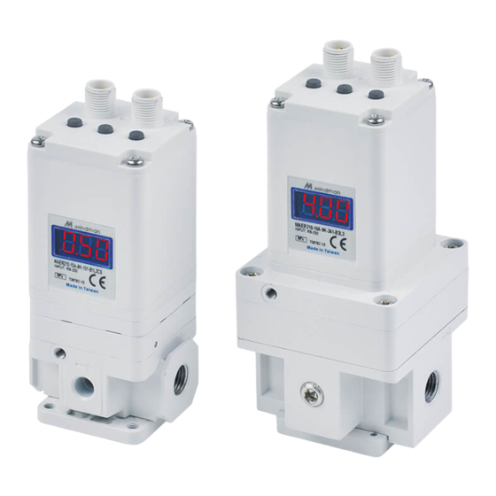
Electro-Pneumatic Regulater
MAER210/310 series
2
3
4
Port size
Pressure range
3
1K: 0.1 MPa
8A: 1/4
5K: 0.5 MPa
10A: 3/8
9K: 0.9 MPa
15A: 1/2
1: MPa
2: kgf/cm
3: bar
4: psi
5: kPa
5
6
7
Bracket
5
Blank: Without
B1: L type
B2: Flat type
Commun. Cable
7
Blank: Without
CS: Straight 3m
2
CL: Right angle 3m
1
8
Power cable
6
Blank: Without
S3: Straight 3m
L3: Right angle 3m
Port thread
8
Blank: Rc thread
G: G thread
NPT: NPT thread
RS-232
Advertisement

Related Manuals for Mindman MAER210/310 Series


Summary of Contents for Mindman MAER210/310 Series
- Page 1 2022/8 SERVICE MANUAL Electro-Pneumatic Regulater RS-232 MAER210/310 series Order example MAER210 – 8A – 9K – 101 – B1 S3 CS – Model Port size Pressure range Bracket Power cable 1K: 0.1 MPa Blank: Without Blank: Without 8A: 1/4 5K: 0.5 MPa...
- Page 2 To ensure safe operation, please read this service manual carefully before use. When desingning and manufacturing equipment using Mindman products, the manufacturer isobligated to ensure that the safety of the mechanism, pneumatic conrtol circuit and/or air control circuit and the system that runs the electrical controls are secured.
- Page 3 Precaution The product characteristics are confined to no flow in the pipeline. When air is consumed on the output side, pressure may become unstable. In order to avoid the error caused by noise, please take the following measures: Set the line filter on AC power line to remove the power noise. Keep the product away from the engine and power line to avoid noise affects.
-
Page 4: Installation Instructions
Installation instructions The 4-Pin port on the right side is the power supply port. Please refer to page 5 for details on the wiring method. The 5-Pin port on the left side is the communication interface. Please refer to page 5 for details on the wiring method. -
Page 5: Wiring Method
Wiring method WARNING Please confirm the product specification and read wiring method carefully before wiring. The color of connector pins and cable conductors must be checked when wiring. Check wire color with handling precaution, since improper wire connection leads to destruction/-failure and malfunction. -
Page 6: Communication Specification
Communication specification Item Specification Protocol RS-232 Baud rate 19,200 bps (Default) Transmission format setting 8,N,1 (Default) Start bit 1 bit Data length 8 bit Stop bit 1 bit Parity Flow control Command end code CR/LF Character-code ASCII... - Page 7 COMMUNICATION PROTOCOL Note. The character-code used to communicate is ASCII. Please use capital letter to command. Please do not put space between the command and the numerical value. If the command is not answered correctly, please confirm whether the content exceeds the allowable range or undefined, or check whether the communication settings are correct.
- Page 8 COMMUNICATION PROTOCOL Definition Command Response Content Valve Gain Coefficient GN=BB Done BB Change value to increase or decrease Valve Gain Coefficient the pressure regulation speed. Range: 1~26 Sensitivity SB=BB Done BB Set pressure allowable fluctuation Sensitivity range. Range: 1~16 Zero Function ZERO Done ZERO Display value set to zero.
-
Page 9: Manual Operation
Manual operation Unlock keys: Press for more than 2 seconds to display Loc, and then press S to unlock keys. Lock keys: Press for more than 2 seconds to display unL, and then press S to lock keys. Flow chart Power on Run mode Unlock keys... - Page 10 Display character and function comparison table Note: The Address number setting is nonfunctional in RS-232 type. Valve Gain Air supply Min. value of the Coefficient solenoid valve set pressure range (GN) basic duty Exhaust solenoid Sensitivity Max. value of the valve basic duty (SB) set pressure range...
- Page 11 Actual situation and parameter application According to different use conditions and occasions, the parameters of the air supply and exhaust valves can be adjusted to ensure that the product meets the needs of use. Pressure-raising application Description: Actual curve Pressure The secondary pressure still fluctuates Ideal curve violently after a period of time and cannot...
- Page 12 Actual situation and parameter application According to different use conditions and occasions, the parameters of the air supply and exhaust valves can be adjusted to ensure that the product meets the needs of use. Pressure-raising application Description: Pressure Ideal curve The secondary pressure still fluctuates violently after a period of time and cannot Actual curve...
- Page 13 Example Pressure setting can be done by sending input data to the electro-pneumatic regulator from the master PLC. Ex1. Target pressure is 3.00 kgf/cm Step1. Set the pressure unit. Command Response Content UNIT=sss Done sss Set the required pressure unit. Note.
- Page 14 2022/8 SERVICE MANUAL Electro-Pneumatic Regulater RS-485 MAER210/310 series Order example MAER210 – 8A – 9K – 101 – B1 S3 CS – Model Port size Pressure range Bracket Power cable 1K: 0.1 MPa Blank: Without Blank: Without 8A: 1/4 5K: 0.5 MPa...
- Page 15 To ensure safe operation, please read this service manual carefully before use. When desingning and manufacturing equipment using Mindman products, the manufacturer isobligated to ensure that the safety of the mechanism, pneumatic conrtol circuit and/or air control circuit and the system that runs the electrical controls are secured.
- Page 16 Precaution The product characteristics are confined to no flow in the pipeline. When air is consumed on the output side, pressure may become unstable. In order to avoid the error caused by noise, please take the following measures: Set the line filter on AC power line to remove the power noise. Keep the product away from the engine and power line to avoid noise affects.
- Page 17 Installation instructions The 4-Pin port on the right side is the power supply port. Please refer to page 5 for details on the wiring method. The 5-Pin port on the left side is the communication interface. Please refer to page 5 for details on the wiring method.
- Page 18 Wiring method WARNING Please confirm the product specification and read wiring method carefully before wiring. The color of connector pins and cable conductors must be checked when wiring. Check wire color with handling precaution, since improper wire connection leads to destruction/-failure and malfunction.
- Page 19 Communication specification Item Specification Protocol RS-485 Address (Default) Baud rate 19,200 bps (Default) (Default) Transmission format setting 8,N,1 Start bit 1 bit Data length 8 bit Stop bit 1 bit Parity bit Flow control Character-code COMMUNICATION PROTOCOL Read / Write Code Description 0x03 Read parameter setting value...
- Page 20 COMMUNICATION PROTOCOL Note. The character-code used to communicate is MODBUS RTU. If the command is not answered correctly, please confirm whether the content exceeds the allowable range or undefined, or check whether the communication settings are correct. Function Item Explanation Operation code 1.
- Page 21 COMMUNICATION PROTOCOL Function Item Explanation Operation code Transmission format setting Read 000A 1: 8.N.1 (Default) 2: 8.O.1 Write 3: 8.E.1 4: 8.N.2 Air supply solenoid valve basic duty value Read 000B Range: 1~255 (unit: 0.1 ms) Write Exhaust solenoid valve basic duty value Read 000C Range: 1~255 (unit: 0.1 ms)
- Page 22 Manual setting method Unlock keys: Press for more than 2 seconds to display Loc, and then press S to unlock keys. Lock keys: Press for more than 2 seconds to display unL, and then press S to lock keys. Flow chart Power on Run mode Unlock keys...
- Page 23 Display character and function comparison table Valve Gain Min. value of the Air supply solenoid Coefficient (GN) set pressure range valve basic duty Exhaust solenoid Sensitivity Max. value of the valve basic duty (SB) set pressure range value Air supplysolenoid Zero Function Switch output valve additional...
- Page 24 Actual situation and parameter application According to different use conditions and occasions, the parameters of the air supply and exhaust valves can be adjusted to ensure that the product meets the needs of us. Pressure-raising application Description: Actual curve The secondary pressure still fluctuates Pressure violently after a period of time and cannot Ideal curve...
- Page 25 Actual situation and parameter application According to different use conditions and occasions, the parameters of the air supply and exhaust valves can be adjusted to ensure that the product meets the needs of us. Pressure-raising application Pressure Ideal curve Description: The secondary pressure still fluctuates Actual curve violently after a period of time and cannot...
- Page 26 Example Pressure setting can be done by sending input data to the electro-pneumatic regulator from the master PLC. Ex1. Target pressure is 3.00 kgf/cm Step1. Set the pressure unit. (REQUEST) Slave Address Write Function Code Data CRC CheckSum 0x01 0x06 0x00 0x03 0x00 0x04 0x78 0x09...
Need help?
Do you have a question about the MAER210/310 Series and is the answer not in the manual?
Questions and answers