Table of Contents
Advertisement
Quick Links
Advertisement
Table of Contents

Related Manuals for ADInstruments ML1101

Summary of Contents for ADInstruments ML1101
- Page 1 INSTRUMENTS making science easier ML1101 Stimulus Isolator Owner’s Guide...
- Page 2 Th is document was, as far as possible, accurate at the time of release. However, changes may have been made to the soft ware and hardware it describes since then. ADInstruments Pty Ltd. reserves the right to alter specifi cation as required. Late-breaking information may be supplied separately.
- Page 3 This alerts the user to imminent death or serious injury arising DANGER : from misuse of the stimulator. This alerts the user to possible death or serious injury arising from WARNING : misuse of the stimulator. This alerts the user to possible injury or damage to property arising CAUTION : from misuse of the stimulator.
- Page 4 GENERAL HANDLING PRECAUTIONS This device is intended for use only by qualified medical personnel. Use only our approved products with this device. Use of non-approved products or in a non- approved manner may affect the performance specifications of the device. This includes, but is not limited to, batteries, recording paper, pens, extension cables, electrode leads, input boxes and AC power.
- Page 5 CAUTION United States law restricts this device to sale by or on the order of a physician. Operator’s Manual 1101...
- Page 6 EMC RELATED CAUTION This equipment and/or system complies with the International Standard IEC 60601-2 for electromagnetic compatibility for medical electrical equipment and/or system. However, an electromagnetic environment that exceeds the limits or levels stipulated in IEC 60601-1-2, can cause harmful interference to the equipment and/or system or cause the equipment and/or system to fail to perform its intended function or degrade its intended performance.
- Page 7 8. Use of unspecified configuration: When the equipment and/or system is used with the unspecified system configuration different than the configuration of EMC testing, it may cause increased electromagnetic emission or decreased electromagnetic immunity. Only use this equipment and/or system with the specified configuration. 9.
-
Page 9: Table Of Contents
Contents Device Overview ............... 2 Introduction ................2 Features ................2 Parts and Functions ..............3 Operation .................. 4 Connections ................4 Output setup for constant voltage stimulation ....... 5 Output setup for constant current stimulation ......5 Precautions ................6 Maintenance ................ -
Page 10: Device Overview
Device Overview Introduction This isolator is designed to be used together with an electronic stimulator (1001) for electric stimulation. This device insulates the output from ground. This minimizes the area of stimulation to produce stimulation with greater precision while reducing stimulation artifacts, facilitating observation of evoked action potential. -
Page 11: Parts And Functions
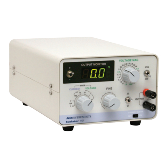
Parts and Functions Front panel Rear panel Description Part 1 +/–: Selects the polarity of the stimulator output to display on the OUTPUT MONITOR 2. Stimulator output display polarity switch This setting is not related to 7. +: Displays the positive pulse of the stimulator output on the OUTPUT MONITOR 2. -
Page 12: Operation
Operation Connections Connect this device to our electronic stimulator (1001). CAUTION Do not touch the connector pins. Discharge electrostatic energy by touching a grounded metal part before connecting. The instrument may be damaged by electrostatic energy. Connect the power cable of the electronic stimulator. Note: For information on how to connect the power cable of the electronic stimulator and how to connect it to ground, refer to the Operator’s... -
Page 13: Output Setup For Constant Voltage Stimulation
Output setup for constant-voltage stimulation Set the electronic stimulator in operating mode and set the output voltage to maximum. Use the +/– switch (Stimulator output display polarity switch) to select the output polarity to be displayed on the OUTPUT MONITOR. VOLTAGE MAG S T I M / O F F OUTPUT MONITOR... -
Page 14: Precautions
Precautions Make sure that the electronic stimulator is turned off before connecting this isolator. Never leave the device in an overload condition (output terminals short- circuited) for five minutes or more. When the CURRENT ALARM switch is on, the constant-current range over alarm indicates that the isolator output dynamic range is not sufficient with regard to the load electrode resistance and cannot let through the current at the set value. -
Page 15: Maintenance
Maintenance CAUTION When maintaining (cleaning, sterilizing, etc.) the stimulator, be sure to turn the power off and unplug the power cable from the power outlet first. Failure to do so may result in an electric shock or malfunction. After Use Inspection Be sure to conduct the following after-use inspections after finishing stimulator use. -
Page 16: Technical Data
Technical Data Standard Performance and Specifications Input specifications Maximum input amplitude: ±10 V or less Input connector: 10-pin connector Isolation method Analog signal transmission through hot coupler Constant-voltage section Rough adjustment: 0.1, 1, 10 V (3-step adjustment) Fine adjustment: Control for continuous adjustment of all ranges Magnification meter: ×1 to ×10 (23-step control) Output maximum current: 10 mA Output impedance: 200 Ω... -
Page 17: Environmental Conditions
Environmental Conditions • Usage environment conditions Operating temperature range: 10 to 40ºC Operating humidity range: 30 to 90% Atmospheric pressure: 70 to 106 kPa • Storage environmental conditions: Storage temperature range: -20 to 65ºC Storage humidity range: 10 to 90% Atmospheric pressure: 70 to 106 kPa Usable Life 6 years (based on self-certification of company data) - Page 18 Guidance and manufacture’s declaration - electromagnetic immunity This Model 1101 is intended for use in the electromagnetic environment specified below. The customer or the user of the 1101 should assure that it is used in such an environment. Electromagnetic environment Immunity test IEC 60601 test level Compliance level...
- Page 19 Guidance and manufacture’s declaration - electromagnetic immunity This Model 1101 is intended for use in the electromagnetic environment specified below. The customer or the user of the 1101 should assure that it is used in such an environment. IEC 60601 test Electromagnetic environment - guidance Immunity test Compliance level...
-
Page 20: Accessories
Recommended separation distances between portable and mobile RF communications equipment and the 1101 This Model 1101 is intended for use in the electromagnetic environment in which radiated RF disturbances are controlled. The customer or the user of the 1101 can help prevent electromagnetic interference by maintaining a minimum distance between portable and mobile RF communications equipment (transmitters) and the 1101 as recommended below, according to the maximum output power of the communications.
Need help?
Do you have a question about the ML1101 and is the answer not in the manual?
Questions and answers