Table of Contents
Advertisement
Quick Links
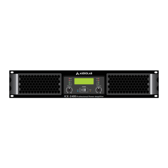
ICE-2400
AC INPUT:
200V-240V~/50-60Hz
CH2 INPUT
CH2 LINK
S/N:
PLEASE READ THE INSTRUCTIONS CAREFULLY BEFORE USE
Power amplifier
PRO
PRO
CLIP
CLIP
SIG
SIG
POW
POW
1
Channel
Channel
POWER
-6
-10
-3
-10
ON
STBY
-15
-15
-30
-1
-30
0dB
I C E -2400
Professional Power Amplifier
INPUT
CH1 INPUT
MODE
PARALLEL
STEREO
BRIDGE
1.0V
0.75V
1.5V
CH1 LINK
SENSITIVITY
ON
OFF
CAUTION:
TURN OFF AMPLIFIER
RING
BEFORE CHANGING
THESE SWITCHES
BRIDGE
TIP
2
-6
-3
-1
0dB
OUTPUT
SPEAKON:
CH 1 OUT:
PIN 1+=
PIN 1-=
BRIDGE:
PIN 1+=
PIN 2+=
CH 2 OUT:
PIN 1+=
PIN 1-=
BRIDGE
USER MANUAL
P. 1
AUDIOLAB ICE SERIES
Advertisement
Table of Contents

Subscribe to Our Youtube Channel
Related Manuals for Audiolab ICE-2400


Summary of Contents for Audiolab ICE-2400
- Page 1 PIN 2+= 1.0V CH 2 OUT: 0.75V 1.5V PIN 1+= PIN 1-= CH2 LINK CH1 LINK SENSITIVITY S/N: CAUTION: TURN OFF AMPLIFIER RING BEFORE CHANGING BRIDGE THESE SWITCHES BRIDGE PLEASE READ THE INSTRUCTIONS CAREFULLY BEFORE USE P. 1 AUDIOLAB ICE SERIES...
-
Page 2: Specifications
Damping factor (1Khz@8 ohms): >800:1 • Signal to noise ratio: >95dB • YSProcessing: The amplifier adds low-frequen- cy compensation to • enhance speaker output. • Protections: Short circuit, open circuit, ther- mal, RF protection, On/off muting, DC fault P. 2 AUDIOLAB ICE SERIES... -
Page 3: Important Safety Instructions
To reduce the risk of electric shock and or pinched particularly at plugs, convenience fire, do not expose this equipment to receptacles, and the point where they exit moisture or rain. from the apparatus. 11. Only use attachments/accessories specified by the manufacturer. P. 3 AUDIOLAB ICE SERIES... -
Page 4: Controls And Functions
#10 or 6mm screws from amplifier. 6. Protect indicator Lights up red to indicate that protection is in effect. Specifically, lights up if the heat sink overheats, or if a DC voltage is detected at the amplifier outputs. Also lights P. 4 AUDIOLAB ICE SERIES... -
Page 5: Rear Panel
The branching is +1,-1(except in bridge mode where the branch- ing is +1,+2 ). 9. Channel 2 Turn Lock Output Connect this turn lock output to a speaker. The balance is +1,-1. P. 5 AUDIOLAB ICE SERIES... -
Page 6: Wire Connections
2. Insert the Neutrik NL4FC plugs into the Speakon connector on the rear of the amplifie, and turn clockwise to lock. Neutrik NL4FC plugs CHANNEL 1 Stereo or Parallel Bridge Out1+ Out1+ Out1- Out2+ Out2+ Out2- CHANNEL 2 Out2+ Out2- P. 6 AUDIOLAB ICE SERIES... -
Page 7: Speaker Connections
When using 5-way binding post output jacks Minimum speaker impedance: 8Ω When using Speakon connector Minimum speaker Minimum speaker impedance: 4Ω impedance: 4Ω When using Speakon connector Minimum speaker impedance: 8Ω Minimum speaker Minimum speaker impedance: 4Ω impedance: 4Ω P. 7 AUDIOLAB ICE SERIES... - Page 8 FOR MORE INFO ON THIS PRODUCT PLEASE CHECK AUDIOLAB.AMPROWEB.COM P. 8 AUDIOLAB ICE SERIES...
Need help?
Do you have a question about the ICE-2400 and is the answer not in the manual?
Questions and answers