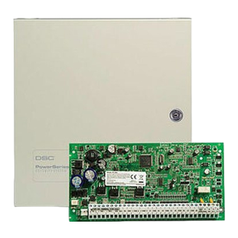
Maxsys PC4020 Installation Manual
Hide thumbs
Also See for PC4020:
- Installation manual (84 pages) ,
- Manual (19 pages) ,
- Instruction manual (3 pages)
Table of Contents
Advertisement
Quick Links
Advertisement
Table of Contents

Related Manuals for Maxsys PC4020


Summary of Contents for Maxsys PC4020
- Page 1 PC4020 v3.0 • Installation Manual DLS-2 v1.3 WARNING: This manual contains information on limitations regarding product use and function and information on the limitations as to liability of the manufacturer. The entire manual should be carefully read.
- Page 2 WARNING Please Read Carefully N o te t o I n s t al le r s This warning contains vital information. As the only individual in contact with system users, it is your responsibility to bring each item in this warning to the attention of the users of this system. S ys te m Fa i lu r e s This system has been carefully designed to be as effective as possible.
-
Page 3: Table Of Contents
Tab le o f C o nt e nt s Section 1: Introduction Section 9: Entry and Exit Delay Out Of The Box ................1 Entry and Exit Delay Times ........... 25 Specifications and Features ............. 1 Entry and Exit Delay Options ..........25 Section 2: Installation and Wiring Section 10: System Programming Planning the System .............. - Page 4 PC402 0 Wiri ng D i ag ra m *Danger of explosion if battery is incorrectly replaced. If the lithium battery stops working, return the circuit board to DSC Ltd. Batteries may cause a fire when in contact with metal. If you need to dispose of the circuit board and/or the lithium battery, wrap the battery in non-conductive tape.
-
Page 5: Section 1: Introduction
1.1 Out Of The Box Expansion Capabilities • Up to 128 zones total using Please verify that the following components are included in the PC4020 package. • PC4108A 8 zone input modules • PC4116 16 zone input modules PC4050C or PC4001C cabinet •... -
Page 6: Section 2: Installation And Wiring
S e ction 2: Installa t i o n an d Wi r i ng 2.1 Planning the System 2.2 Terminal Descriptions The following terminals appear on the PC4020 Alarm NOTE: This system should be installed and serviced by Control Panel: qualified security professionals. -
Page 7: Current Ratings - Alarm Control Panel And Modules
NOTE: For UL, ULC and Commercial Fire applications, the total standby AND alarm current cannot exceed 900mA. PC4020 Module Ratings The current draw of compatible PC4020 modules is listed below: Device ..........Current Draw (mA) Keypad (LCD45XX)............50 The following rules MUST be followed when wiring the PC4108A Zone Expander .......... -
Page 8: Zone Wiring
the wire to calculate the maximum distance (see PC4204 Current Requirement “Capacitance Limits” below). AUX - 1.5A available for devices connected to the AUX 4. The total capacitance of the Combus wiring must not terminal, including devices connected to relay outputs exceed 80nF (see “Capacitance Limits”... -
Page 9: Specialized Zone Wiring
S e c t i o n I n s t a l l a t i o n a n d W i r i n g Single End of Line (EOL) All Single EOL zones have a 5600Ω resistor across them. If the zone is shorted or open, it will be violated. -
Page 10: Programmable Output Wiring
• input debounce time • addressable reporting and confirmation time • processing time required by the panel to activate the output These response times are worst case and typical response will be faster. One loop used: 1 to 32 devices on the loop ........ up to 2.5s 33 to 112 devices on the loop...... -
Page 11: Wiring Powered Devices (Aux, Saux+)
S e c t i o n I n s t a l l a t i o n a n d W i r i n g This configuration is only used for AML devices. Please see the installation sheet provided with each device for more information regarding operation and wiring. -
Page 12: Applying Power (Ac And Battery)
If the lithium battery stops working, return the circuit The PC4020 monitors the presence of AC. Upon the loss board to DSC Ltd. Batteries may cause a fire when in of AC power a trouble condition will be generated. The contact with metal. -
Page 13: Section 3: How To Program
Press [#] to return to the previous menus and to exit the installer programming mode. The PC4020 is programmed via a menu system. Use the arrow keys (<>) to scroll through different menu options The arrow keys (<>) will appear in the top right-hand and press the [*] key to select the menu option displayed. -
Page 14: Programming Hexadecimal Data
Hex letter (A = 1, B = 2, C = 3, up to F = 6). Once the digit is entered, the control panel will automatically return to the decimal programming mode. For example, to enter data ‘ABCD’ on a PC4020 you would enter: [*], [1], [*], [2], [*], [3], [*], [4]... -
Page 15: Section 4: Module Enrollment
S ec t ion 4 : M o du l e E nro l l me nt 4.1 Enrolling Keypads and Modules Zone Expanders Once the wiring of all keypads and modules is complete, NOTE: Enroll all zone expanders before assigning zones to PC4820 and AML devices. -
Page 16: Confirming Modules
Any zone from zone 017 to 128 on Installer’s Programming and enter ref# [00140301]. the PC4020 can be used as an AML zone. If the detector For devices to be deleted from PGM2: Enter is not connected to the PGM terminal, the zone will not Installer’s Programming and enter ref# [00140401]. -
Page 17: Section 5: Partitions And Zones
S e c t io n 5 : Par ti t i o ns and Z o n e s 5.1 Zone Supervision [F] Enabled (Y)..........see Section 6.5 Ref # [000204] “Zone Supervision” [A] Enabled (Y)..........see Section 6.5 The control panel must be instructed to supervise either [P] Enabled (Y) ..........see Section 6.5 No End of Line, Single EOL or Double EOL zone loops. -
Page 18: Adding Zones To Partitions
Scroll to the partition to be deleted, then press [*]. When • When a global zone is manually bypassed, as soon as a partition is deleted, the programming assigned to it any partition the zone is assigned to is disarmed, the will not be erased. - Page 19 S e c t i o n P a r t i t i o n s a n d Z o n e s Standard Fire (07) [0] Clear Display will clear the entire label. [1] Clear to End will clear the display from the character When a Standard Fire zone goes into alarm, the panel above the cursor to the end of the display.
- Page 20 Each zone type has different attributes enabled by • 24 Hr Freeze (21): This zone is audible. default. For a list of these default settings, see the PC4020 • 24 Hr Holdup (22): This zone is silent. It does not acti- Programming Worksheets.
Need help?
Do you have a question about the PC4020 and is the answer not in the manual?
Questions and answers