Table of Contents
Advertisement
Quick Links
Installation, Operation &
Maintenance
Instructions
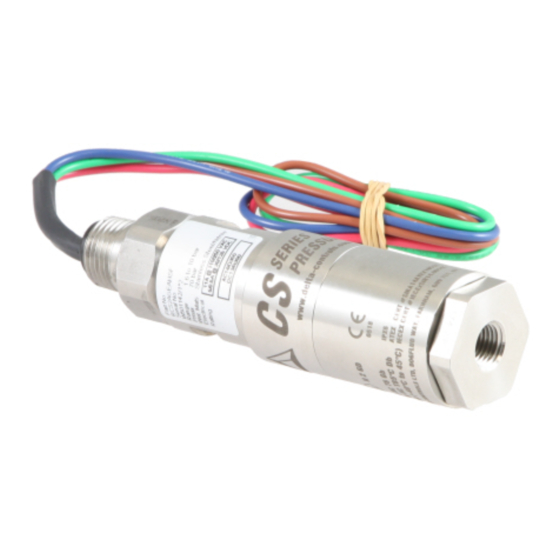
CS Series
Models CS2, CS4 (Pressure Switches)
SAFETY INSTRUCTIONS
Information
...points out useful tips,
recommendations and information
for efficient and trouble-free
operation.
CAUTION!
...indicates a potentially dangerous
situation that can result in light
injuries or damage to equipment or
the environment, if not avoided.
WARNING!
...indicates a potentially dangerous
situation that can result in serious
injury or death, if not avoided.
WARNING!
...identifies hazards caused by
electric power. Should the safety
instructions not be observed, there
is a risk of serious or fatal injury.
WARNING!
...indicates a potentially dangerous
situation that can result in burns,
caused by hot surfaces or liquids, if
not avoided.
WARNING!
...indicates a potentially dangerous
situation in the hazardous area that
can result in serious injury or death,
if not avoided.
Ex applications...special instructions for Ex
applications.
CONTENTS
Foreword
Allowed over range
•
Ambient temperature
•
Process temperature
•
•
Installation
•
•
•
•
Safety Integrity Level (SIL) instrument installation
requirements
•
•
Page 1 of 6
Foreword
The unit is manufactured, checked and supplied in
accordance with our published specification, and when
installed and used in normal or prescribed applications,
with the lid in place and within the parameters set for
mechanical and electrical performance, will not cause
danger or hazard to life or limb.
Warning: Units must be selected and installed by
suitably
accordance with appropriate codes of practice so
that the possibility of failure resulting in injury or
damage caused by misuse or misapplication is
avoided.
Warning: Before installation check that the
instrument characteristics comply with process
and plant requirements
Warning: The user should ensure the equipment is
suitable for use in the application with aggressive
substances.
Warning: The users attention is drawn to the fact
that, when the unit is 'live' with respect to electrical
or pressure supplies, a hazard may exist if the unit
is opened or dismantled.
Warning: Where any special condition of the
product has been required as identified by the last
4 digits of the part number, follow the necessary
safety instruction for a correct installation.
Allowed over range
Pressure exceeding the adjustable range can be allowed
up to the max pressure stated on the nameplate.
Transitory electrical over ranges can have a destructive
effect on the microswitch.
Ambient temperature
The surface temperature of the instrument is influenced by
the process temperature, electrical working conditions,
installation and environmental. Special attention must be
taken to avoid exceeding the limits specified on table
below (i.e. remote mounting, valves, siphons, diaphragm
seals. See Mounting).
Process temperature
The following tables are applicable:
Temperature
Class
T6 .. T5
T4 ... T1
Temperature
Class
T6 .. T5
T4 ... T1
www.delta-mobrey.com
IOM-CS-F: AUG 2022
trained
and
qualified
Ambient
Max process
temperature range
temperature at
process
From –40 to +60°C
60°C
From –40 to +85°C
85 °C
Max process
Ambient
temperature at
temperature range
process
From –40 to +45°C
45°C
From –40 to +85°C
85 °C
personnel
in
Max electrical
loads
(resistive loads)
Up to 5 A (see
nameplate)
Max electrical
loads
(resistive loads)
Up to 11 A (see
nameplate)
Advertisement
Table of Contents

Related Manuals for delta-mobrey CS Series


Summary of Contents for delta-mobrey CS Series
- Page 1 IOM-CS-F: AUG 2022 Installation, Operation & Maintenance Instructions CS Series Models CS2, CS4 (Pressure Switches) Foreword SAFETY INSTRUCTIONS Information ...points out useful tips, The unit is manufactured, checked and supplied in recommendations and information accordance with our published specification, and when...
- Page 2 Fig. 2 - Flameproof nameplate Intrinsically safe models carry the following label markings: Fig. 3 - Intrinsic Safety nameplate Input limitations for intrinsic safety: Ui = 30V, Ii = 300mA, Ci = 1 nF; Li = 6.3 mH Page 2 of 6 www.delta-mobrey.com...
- Page 3 See digit 11 of equipment on which the instrument is installed is product code. suitably earthed. Page 3 of 6 www.delta-mobrey.com...
- Page 4 Gradually adjust the range adjuster and recheck again using the lamp until the set point is achieved with the required accuracy. Slide the cover downwards. Write the set point on the adhesive label Page 4 of 6 www.delta-mobrey.com...
- Page 5 The verification consists of a check of the set instrument and installation point. This verification is done, usually by requirements removing the instrument from the plant and Refer to Functional Safety Manual CS Series. performing the verification in a test room (see periodical /calibration check paragraph). Commissioning Warning: Flameproof instruments.
- Page 6 IOM-CS-F: AUG 2022 Model code Enclosure Model Electrical Entry Material of Wetted Part Range Switch Process Connection Options & Treatments Special Engineering DIMENSIONS Enclosures Styles www.delta-mobrey.com Page 6 of 6 www.delta-mobrey.com...
Need help?
Do you have a question about the CS Series and is the answer not in the manual?
Questions and answers