Table of Contents
Advertisement
Quick Links
Installation, Operation &
Instructions
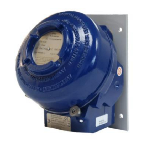
Performance Series
Model 131 (Flow Switch)
General
The unit is manufactured, checked and supplied in
accordance with our published specification, and
when installed and used in normal or prescribed
applications, with the lid in place and within the
parameters set for mechanical and electrical
performance, will not cause danger or hazard to life
or limb.
THE USERS ATTENTION IS DRAWN TO
THE FACT THAT, WHEN THE UNIT IS
'LIVE' WITH RESPECT TO ELECTRICAL
OR PRESSURE SUPPLIES, A HAZARD
MAY EXIST IF THE UNIT IS OPENED OR
DISMANTLED.
UNITS
MUST
INSTALLED BY SUITABLY TRAINED AND
QUALIFIED
ACCORDANCE
CODES OF PRACTICE SO THAT THE
POSSIBILITY OF FAILURE RESULTING IN
INJURY
OR
MISUSE
AVOIDED.
Operating principles
Flow Switch 131 is vane actuated switch.
The sensing element is a pivoted, counter-weighted
vane, which at its rest position lies at right angles to
the direction of flow. The vane is mounted on a shaft,
which carries two cams that operate one or two
microswitches when the shaft is rotated. When the
nominated flow velocity is reached the vane turns
the shaft enough to operate the switch(es).
Two springs constrain the shaft movement. One
compensates for any gravitational effects on the
vane and for the internal spring setting of the switch
(es). The other determines the amount of flow on the
vane to operate the switch(es).
BE
SELECTED
PERSONNEL
WITH
APPROPRIATE
DAMAGE
CAUSED
OR
MISAPPLICATION
www.delta-mobrey.com
IOM-PERFORMANCE-B : SEPT 2019
INSTALLATION
Mounting (All models)
The instruments may be used on flow in any
direction with the operating shaft horizontal or
vertical. The instrument is supplied with the
microswitch set to operate correctly in relation to
rotation of the operating shaft. Vane and counter
weight are supplied separately. Select the mounting
point so as to avoid excessive shock, vibration or
temperature fluctuations. Install far enough away
from bends, tees or obstructions to avoid non-steady
flow. Instruments should be mounted to avoid
excessive heat transfer from adjacent plant.
Provide aperture in duct large enough to accept
AND
counterweight / vane (refer to fig 1). Position the
IN
vane assembly axially along the operating shaft
which may be adjusted to a maximum of 100 mm
from the mounting plate to the vane centre line by
tightening the M3 socket set-screw provided,
BY
ensuring that the screws locate on flat of shaft.
IS
Fig 1
Advertisement
Table of Contents

Related Manuals for delta-mobrey Performance Series


Summary of Contents for delta-mobrey Performance Series
- Page 1 IOM-PERFORMANCE-B : SEPT 2019 Installation, Operation & Maintenance Instructions Performance Series Model 131 (Flow Switch) INSTALLATION General The unit is manufactured, checked and supplied in Mounting (All models) accordance with our published specification, and when installed and used in normal or prescribed...
- Page 2 The following diagram can be used as “COMMON”. LEAST 5 FULL THREADS ARE ENGAGED a guide for wiring. BETWEEN THE COVER / LID AND THE ENCLOSURE WHEN THE UNIT IS IN OPERATION. NEVER OPERATE THE UNIT UNLESS THIS CONDITION IS MET. ATEX www.delta-mobrey.com...
- Page 3 Each spring may be adjusted via an M4 hexagon screw, rotating clockwise to increase tension and thus reducing flow sensitivity. Fig 5 www.delta-mobrey.com...
- Page 4 Do not attempt to remove the assembly and if in doubt seek assistance from Delta Mobrey. www.delta-mobrey.com...
Need help?
Do you have a question about the Performance Series and is the answer not in the manual?
Questions and answers