Table of Contents
Advertisement
Quick Links
RTS 3P2 HISTORIC SIXTIES LE MANS PIT BUILDING
CONGRATULATIONS
Congratulations in choosing a unique product to enhance your slot car track
diorama. This can truly be described as a product born from a love for slot cars.
Buying this product have made you a member of a very special family, yes you are
not dealing with a faceless business, but rather a family of slot car fanatics.
We put hours of skill and more importantly love into our products and it is wonderful
to share our love for slot cars with you. May you enjoy the build and have years of
joy having it as part of your trackside diorama.
This structure is not a replica of a specific pit building, but it inspires to capture the
ambiance of the pits that were found at raceway tracksides like Le Mans. We believe
that this building will enhance any trackside diorama and bring some character to the
layout. This building comes with a very special work bench.
WARRANTY
This product is covered by a comprehensive money-back warranty to ensure your
absolute satisfaction with your purchase.
WHO ARE WE?
This product is brought to you by racetrackscenics.com. If you have not done so
already, please visit our website today. You are also most welcome to visit the
Facebook pages
"Race Track Scenics Slot Car Scenery" and "Johan Malan" to keep
up to date with the latest developments and the launching of exciting new products
that may be in the pipeline.
You can contact Kevin Sharpe on
Email: racetrackscenics@gmail.com
Text in the USA 586 549 2879
WhatsApp 1-586-549-2879
for any assistance that you might require. Your feedback and a photo or two of your
trackside addition will really be appreciated. We love to share in your joy!
WHAT IS IN THE KIT?
In this kit you will find all the laser cut pieced needed to assemble this product. The
pieces are still intact in the sheets as they were cut to ensure that all the parts are
there. Some of the loose bits inside pieces may have been removed, but they are not
part of the finished product. In the section "FAMILIARIZE YOURSELF" below, you
ASSEMBLY INSTRUCTIONS
1
Advertisement
Table of Contents

Subscribe to Our Youtube Channel
Related Manuals for RTS 3P2


Summary of Contents for RTS 3P2
- Page 1 ASSEMBLY INSTRUCTIONS RTS 3P2 HISTORIC SIXTIES LE MANS PIT BUILDING CONGRATULATIONS Congratulations in choosing a unique product to enhance your slot car track diorama. This can truly be described as a product born from a love for slot cars. Buying this product have made you a member of a very special family, yes you are not dealing with a faceless business, but rather a family of slot car fanatics.
- Page 2 will find diagram(s) that identify and explain each piece (component) that you are about to assemble. In the section “PREPARING THE CUT PIECES” below, you will learn how to proceed to prepare the pieces for assembly. In the kit you will also find some optional pre-cut artwork printed on matt photo paper.
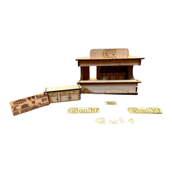
- Page 3 FAMILIARIZE YOURSELF Have a look at a photo of the finished product. (NOTE: This kit comes with pre- printed artwork lately and the work bench have been simplified.) Now have a look at the diagram where all the laser cut parts are shown and numbered from A to H.
- Page 4 You will notice the four walls (A), (B), (C) and (D) that fits into the floor (G). There is a work surface (E) that fits onto the front portion of the side walls (A) and (B). There is a name board (F) that fits between the top ends of the side walls (A) and (B).
- Page 5 WORD OF ADVICE We would strongly advise you to do a quick dry assembly before you start gluing the laser cut parts together. Lay out all the parts on your work surface and make sure that the parts are not upside down or mirrored. In most instances it will make no difference, but in others it may be crucial to ensure a perfect product in the end.
- Page 6 Proceed to glue the slots of the work surface (E) to the nubs of the front portion of the two side walls (A) and (B). Lastly the roof (H) which fits over the name board and sits on the side walls can be glued in position. The work bench with a tool wall is constructed from the back panel (A), the two sides (C) and (D), the front panel with doors (E) and a work surface (B).
Need help?
Do you have a question about the 3P2 and is the answer not in the manual?
Questions and answers