
Subscribe to Our Youtube Channel
Related Manuals for OSS SDS-3U-4i


Summary of Contents for OSS SDS-3U-4i
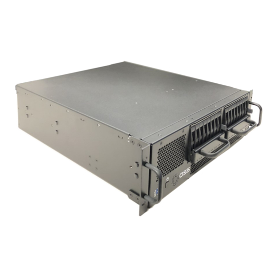
- Page 1 PCIe Gen 4 3U Short Depth Intel Server SDS-3U-4i User Manual SKU: SDS-3U-4i www.onestopsystems.com...
-
Page 2: Table Of Contents
Front Panel Drive LEDs ..............................24 LED Color Definition ........................... 24 Drive Slot & Bracket LINK Status LEDs ...........................25 How to Access Motherboard BMC Web Interface ......................28 Configuring the BMC in the BIOS ...........................30 How to Remove Power Supply Module .........................31 OSS-SDS-3U-4i (Intel) - Page 3 One Stop Systems How to Remove Top Cover ............................32 How to Add / Remove PCIe Card ...........................33 OSS Host Card Installation (Gen 4) ..........................34 Attach OSS Expansion Unit ............................35 14.1 Connect LINK Cables (Gen 4) ........................35 M.2 NVME Installation ..............................36 15.1...
- Page 4 Hierarchy of NVME Drives – Windows OS ........................53 Hierarchy of NVME Drives – Linux OS ..........................61 Contacting Technical Support ............................64 Returning Merchandise to One Stop Systems ........................64 2241 Shipping / transporting the card ........................ 64 APPENDIX A Compliance .............................65 OSS-SDS-3U-4i (Intel)
-
Page 5: Preface
Disclaimer: We have attempted to identify most situations that may pose a danger, warning, or caution condition in this manual. However, One Stop Systems does not claim to have covered all situations that might require the use of a Caution, Warning, or Danger indicator. OSS-SDS-3U-4i (Intel) -
Page 6: Safety Instructions
As you pull connectors apart, keep them evenly aligned to avoid bending any connector pins. Also, before connecting a cable, make sure both connectors are correctly oriented and aligned. CAUTION Do not attempt to service the system yourself except as explained in this manual. Follow installation instructions closely. OSS-SDS-3U-4i (Intel) -
Page 7: Protecting Against Electrostatic Discharge
Handle all sensitive components at an ESD workstation. If possible, use anti-static floor pads and workbench pads. Handle components and boards with care. Do not touch the components or contacts on a board. Hold a board by its edges or by its metal mounting bracket. OSS-SDS-3U-4i (Intel) -
Page 8: General Specifications
8x and 16x NVMe x2 slots require 1 and 2 x16 PCIe HHHL slots respectively • Further expansion up to 4PB possible using OSS JBOF expansion systems such as the SB2000 • 2x M.2 x4 and 2x SATA-DOM internal drive connections... -
Page 9: Features
System Monitoring • AC or DC Input Power Supplies • Resource expanded BIOS for large expansion capability • Guaranteed to operate with all OSS expansion products Overview Description OSS LOGO & LED Power Button USB Ports Front Rack Ears / Handles... - Page 10 One Stop Systems Description Internal Fan Motherboard OSS-536: Storage Drives Controller Ethernet Cable: Connection to IPMI module IPMI Module Aux Power Connectors ATX Power Connector / Cable Drive Pack / Storage Housing OSS-SDS-3U-4i (Intel)
-
Page 11: Motherboard Layout
One Stop Systems Motherboard Layout OSS-SDS-3U-4i (Intel) -
Page 12: Quick Reference
One Stop Systems Quick Reference OSS-SDS-3U-4i (Intel) -
Page 13: Reference Table
NC-SI (Network Controller Sideband Interface) Connector JNV2C NVMe PC Header JPI2C1 Power System Management Bus (SMB) PC Header JPWR1 24-pin ATX Power Connector JPWR2, JPWR3, JPWR4 8-pin Power Connectors 4-pin Power Connector JPWR5 JSD1, JSD2 SATA DOM Power Connectors JSEN1 Inlet Sensor Header OSS-SDS-3U-4i (Intel) - Page 14 Front-accessible USB Header with support for two USB 3.0 port USB8 (3.0) Internal USB 3.0 Type-A Header VGA1 Front VGA Header VGA2 Rear VGA Port on the I/O back panel VROC (JRK1) Intel VROC Key Header for NVMe RAID support OSS-SDS-3U-4i (Intel)
-
Page 15: Motherboard Features
• Low-noise fan speed control • Ten 4-pin fan headers LED Indicators • Power LED • UID/remote UID • LAN activity LED • BMC Heartbeat LED Dimensions 15.12" (W) x 13.2" (L) ATX (384.05 mm x 335.28 mm) OSS-SDS-3U-4i (Intel) -
Page 16: Setting Up
Press the front switch button to turn ON the unit. Upon powering ON the unit, the following LEDs will illuminate • LOGO will illuminate as sold blue. • Power supply LEDs will illuminate as solid green. Blinking green, indicates the unit is on standby mode. OSS-SDS-3U-4i (Intel) -
Page 17: Log In
Solid Amber: No Activity. Blinking Amber: Activity If only AMBER LEDs are illuminated, the IPMI module is malfunctioning, or the firmware is corrupted / not installed. Contact Technical Support for assistance, send the unit to OSS for service. Log in You can log in to the Linux system using the following account credentials. -
Page 18: Verify Pcie Cards / Devices
The following are the PCIe cards installed in the SDS unit. Other models may not have all the PCIe cards installed. 1. OSS-536 card (storage controller card) 2. One or two NVIDIA GPUs 3. One Mellanox card (optional) To check the OSS storage controller card (OSS-536): lspci -vvv | grep 02b2 OSS-SDS-3U-4i (Intel) - Page 19 One Stop Systems To check the NVIDIA GPUs: #nvidia-smi. See output below To check on the NVME drive: #nvme -list. See sample output below. To check on Mellanox: #lspci | grep Mellanox OSS-SDS-3U-4i (Intel)
-
Page 20: Storage Drive Installation
Grab the Drive pack front handle and gently pull the Drive pack away from the enclosure. Set the Drive pack on a solid surface. Remove the mounting screw on each side. Dismount the handle to access the drive trays. OSS-SDS-3U-4i (Intel) -
Page 21: Install Storage Drive
Place the Drive pack on a solid surface in a vertical position. When installing 8 drives, start installing the drive tray from the far-end right drive slot. This would give you visibility on the board slot during the drive tray installation. OSS-SDS-3U-4i (Intel) - Page 22 Make sure the drive connector is fully seated in the drive slot, see photo below Push the drive tray into the hard drive bay as illustrated below, until the drive tray clicks into the locked position. Using the thumb, push against the lower part of the hard drive handle. OSS-SDS-3U-4i (Intel)
-
Page 23: Reinstall The Drive Pack
One Stop Systems Reinstall the Drive pack Reinstall the front handle and secure it (with two mounting screws, one per side). Push the Drive pack into the enclosure. Turn both thumbscrews clockwise to secure. OSS-SDS-3U-4i (Intel) -
Page 24: Front Panel Drive Leds
If the system is equipped with IPMI module and only AMBER LEDs are illuminated, this is an indication that the IPMI module is not working correctly or the IPMI software is corrupted. Contact OSS Technical Support for assistance, you may need to send the unit back to One Stop Systems for service. -
Page 25: Drive Slot & Bracket Link Status Leds
The drive slot is tied to a “Bracket LINK STATUS LEDs” on the OSS-536 board, see photo below. Photo below shows the OSS-536 board in the SDS appliance. Photos below show the location of the Bracket LINK STATUS LEDs. OSS-SDS-3U-4i (Intel) - Page 26 NOTES: Storage drive slots 1, 3, 5 and 7 are not connected to the LINK STATUS LED. No LINK STATUS LED associated with these drive slots will illuminate when drive is present except the LED located on the front OSS-SDS-3U-4i (Intel)
- Page 27 NOTES: storage drive slots 1, 3, 5 and 7 are not connected to the LINK STATUS LED. No LINK STATUS LED associated with these drive slots will illuminate when drive is present except the LED located on the front. OSS-SDS-3U-4i (Intel)
-
Page 28: How To Access Motherboard Bmc Web Interface
Power up the SDS system, during boot up, the BMC IP address will show up on the screen, see photo below as an example. Start the internet browser and enter the BMC IP address, for example 192.168.1.124. The below login page should appear. The default username is ADMIN, and the password is ADMIN. OSS-SDS-3U-4i (Intel) - Page 29 Power Source - show the current readings of power supplies. Also shows the temperature from the power supplies For more information regarding the SuperMicro SMT IPMI interface and settings click the below link: https://www.supermicro.com/products/nfo/IPMI.cfm Login as “Admin,” password is “Admin” OSS-SDS-3U-4i (Intel)
-
Page 30: Configuring The Bmc In The Bios
6. Connect an Ethernet cable to the IPMI LAN Port located on the back of the unit. Connect the other end of the cable to your network. 7. Save BIOS setting and restart / exit. 8. During boot up, the splash screen will flash the BMC IP address. OSS-SDS-3U-4i (Intel) -
Page 31: How To Remove Power Supply Module
This section will demonstrate on how to dismount or detach the power supply. 1. Disconnect the power cord from the power supply 2. Grasp the power-supply handle. 3. Press the blue release latch (from right to left) and hold it. 4. Pull the power supply out of the bay. OSS-SDS-3U-4i (Intel) -
Page 32: How To Remove Top Cover
After removing all the screws, stand at the front of the unit, place each hand on the side, both hands grasping the side of lid, push the lid to dislodge. Gently pull the lid from the back and lift it up OSS-SDS-3U-4i (Intel) -
Page 33: How To Add / Remove Pcie Card
4. Place the card hold-down bracket on top of the card brackets and use two screws to secure it down. Remove the screws, see photo below for the location of the screws. Detach the card-hold down bracket. Install your PCIe card and secure it. OSS-SDS-3U-4i (Intel) -
Page 34: Oss Host Card Installation (Gen 4)
One Stop Systems OSS Host Card Installation (Gen 4) Power down the system first before installing any PCIe cards. • Remove the power cord. 5VSB (5V Standby) is still available if the power cord is still installed. The SDS unit support full height PCIe host card. Photos below show the difference between full height and half height brackets. -
Page 35: Attach Oss Expansion Unit
Attach OSS Expansion Unit This section shows on how to connect an OSS Expansion unit to the SDS system. Make sure you are using the same model of Target and Host adapter cards (i.e., OSS-OSS-PCIE-HIB616-X16). 14.1 Connect LINK Cables (Gen 4) In this example we are connecting a Gen4 expansion unit. -
Page 36: Nvme Installation
Secure the M.2 media using the mounting screw. Press down and hold the M.2 SSD while you replace the mounting screw that was removed in Step 1. • This will secure the M.2 media in place. See photos below. OSS-SDS-3U-4i (Intel) -
Page 37: Verify M.2 Media
BIOS and set the settings that an M.2 device is connected. 1. Power UP the computer, during the boot-up process, press “Delete” to enter BIOS. 2. Go to Advanced Tab, select, and hit NVME Firmware Source, from the list select “AMI Native Support.” OSS-SDS-3U-4i (Intel) - Page 38 Click "Boot Mode Select", from the dropdown list select "Dual" b. Click "LEGACY to EFI Support", from the dropdown list select "Enabled" Click "Boot Option #1, find and select the "NAME of your Storage Device" 4. Go to "Save & Exit" tab, click "Save Changes and Reset" OSS-SDS-3U-4i (Intel)
-
Page 39: Ipmi
Power supply voltage and temperature 16.1 Check IPMI Hardware Check if the unit is equipped with IPMI. Remove the top cover of the appliance. 16.2 IPMI Module Location See photos below for the location of the IPMI module. OSS-SDS-3U-4i (Intel) -
Page 40: Ipmi Set Up
Plug in the other end of the Ethernet cable to your network (running DHCP). 17.2 Connect Power Cables Connect the power cords to the power supplies, located on the back of the unit. Press the front power button to turn ON the SDS system. OSS-SDS-3U-4i (Intel) -
Page 41: Locate Mac Address
Mac address. The photo below shows the location of the IPMI module label. The OSS IPMI module Mac address contains thirteen characters / numbers. Use only the twelve numbers written on the label, this is the primary Mac address. -
Page 42: Discovering The Mac Address / Ip Address
Go to “DHCP” then to “DHCP Clients List” here, and you will be able to see how the MAC and IP addresses are mapped on the network. • Match the IP with the MAC address. Navigate to Data management->DHCP->Leases->Current leases in the GUI and you can export it to check the list of clients involved. OSS-SDS-3U-4i (Intel) -
Page 43: Using A Network Or Ip Scanner
You should be able to find your MAC of your device, with its IP address. In this example, the MAC Address on the IPMI module Eth0 is 00-18-49-F1-B8. Match that with the IP address on the “arp” table, it is 10.2.5.2, see example photo below. OSS-SDS-3U-4i (Intel) - Page 44 This is just one an example of PowerShell command that you can utilize. There are more commands available that you can use. Linux: Photos below are an example of Linux commands to query the IP address and Mac address. OSS-SDS-3U-4i (Intel)
-
Page 45: Start Internet Browser
Once the IP address is identified, launch your internet browser, and type the IP address. Below photo is the Web interface of the IPMI displaying the status of the following hardware in the storage expansion unit. • Fan status and speed • Drive Backplane temperature • Power supply voltage and temperature OSS-SDS-3U-4i (Intel) - Page 46 One Stop Systems OSS-SDS-3U-4i (Intel)
-
Page 47: How To Login To Ipmi Console
Once you have the Terminal Window or the Command Prompt started: • Type "ssh root@XXX.XXX.X.XXX". Press the ENTER key NOTE: Replace the XXX.XXX.X.XXX with the address assigned to your OSS Storage Expansion unit. • There is no password, press ENTER again. -
Page 48: Ipmi Command Lines
To change the network settings, run setip. This will ask for the settings for both network interfaces again. To change the fan control speed, go to /home/root directory and enter. /ipmi_ctrl Note: This can only control the fan speed on the large front fan. To change IP address, go to /home/root directory and enter ./setip.sh OSS-SDS-3U-4i (Intel) -
Page 49: Drive Packs
There are two Drive Packs in the SDS unit. • Each Drive Pack contains 8 drives / 8 drive slots. • The Drive Packs are linked to an OSS-536 PCIe storage controller card. • Below are the slot assignments for each drive slot. Figure 1: 8 Drive trays Figure 2: 8 drive slots on the midplane. -
Page 50: Slot / Port Mapping
20.1 Slot / Port Mapping FIG 3: The OSS-536 card (storage controller card) is connected to both drive packs (#1 and #2) via SFF-8643 cables. FIG 3 Drawing below shows the connection between the OSS-536 board and the Drive Packs. -
Page 51: Oss-536 Port Mapping
Drive Pack 1, Slot 3 Drive Pack 1, Slot 2 Drive Pack 1, Slot 1 PCIe Card Edge 20.2 OSS-536 LEDs / Board LEDs: CR7: Fatal Error CR8: PEX Switch Heartbeat, 1Hz CR14: PCIe Reset Asserted D9: AUX Power Good... - Page 52 One Stop Systems FIG 4: Shows the associated drive slots (2,4,6 and 8) from drive pack#1 and their corresponding link status LEDs (0,1,2 and 3) from the OSS-536. FIG 4 FIG 5: Shows the associated drive slots (2,4,6 and 8) from drive pack#2 and their corresponding link status LEDs (5,6,7 and 8) from the OSS-536.
-
Page 53: Hierarchy Of Nvme Drives - Windows Os
One Stop Systems Hierarchy of NVME Drives – Windows OS Hierarchy of 16 NVME drives in Windows Device Manager, viewing it “Devices by Connection”. FIG 6 OSS-SDS-3U-4i (Intel) - Page 54 One Stop Systems FIG 7 OSS-SDS-3U-4i (Intel)
- Page 55 One Stop Systems FIG 8: Viewing the 16 storage devices using the “Disk Management” tool. OSS-SDS-3U-4i (Intel)
- Page 56 One Stop Systems The screenshot below shows 8 detected NVME drives in Windows Device Manager from Drive Pack #2. FIG 9 OSS-SDS-3U-4i (Intel)
- Page 57 One Stop Systems The screenshot below shows 8 detected NVME drives in Windows Device Manager from Drive Pack #1. FIG 10 OSS-SDS-3U-4i (Intel)
- Page 58 Screenshot below shows 16 PCI Express Downstream Switch Ports • It represents the drive slot in the drive packs (#1 and #2). • The 17th PCI Express Downstream Switch Port is the SAS Controller (OSS-563). FIG 11 16 PCI Express Downstream Switch Ports SAS Controller: OSS-536 card...
- Page 59 • When the Operating System detects the NVME drive, an instance of "Standard NVME Controller" will appear below the "PCI Express Downstream Switch Port". Under the "Standard NVME Express Controller", the NVME storage device will appear. FIG 12 OSS-SDS-3U-4i (Intel)
- Page 60 One Stop Systems FIG 13: Showing 16 NMVE drives enumerated, viewing “devices by type” in Windows Device Manager. FIG 13 OSS-SDS-3U-4i (Intel)
-
Page 61: Hierarchy Of Nvme Drives - Linux Os
To check the hierarchy of 16 NVME drives (in Drive Pack#1 and #2), use the command #lspci -vvvt | grep 'KIOXIA,’ • Replace the “KIOXIA” with your storage NVME drive vendor name. • FIG 15: 16 NVME drives enumerated; 8 drives in Drive Pack #1 and 8 drives in Drive Pack #2. FIG 15 OSS-SDS-3U-4i (Intel) - Page 62 #lspci -vvvt | grep 'KIOXIA\|Broadcom'. • Replace the “KIOXIA” with your storage NVME drive vendor name. • FIG 17: 8 NVME drives enumerated; 8 drives in Drive Pack #2. No drives installed in Drive Pack #1. FIG 17 OSS-SDS-3U-4i (Intel)
- Page 63 One Stop Systems To check on NVME drives and their assigned BUS numbers, use command below. #lspci | grep KIOXIA FIG 18: The characters shown on the left are the assigned bus numbers. OSS-SDS-3U-4i (Intel)
-
Page 64: Contacting Technical Support
Returning Merchandise to One Stop Systems If factory service is required, you must contact OSS Service Representative to obtain a Return Merchandise Authorization (RMA) number. Put this number and your return address on the shipping label when you return the item(s) for service. One Stop Systems will return any product that is not accompanied by an RMA number. -
Page 65: Appendix A Compliance
This Class A digital apparatus complies with Canadian ICES-003. Cet appareil numériqué de la classe A est conformé à la norme NMB-003 du Canada The product(s) described in this manual complies with all applicable European Union (CE) directives. One Stop Systems will not retest or recertify systems or components that have been reconfigured by customers OSS-SDS-3U-4i (Intel) - Page 66 One Stop Systems 2235 Enterprise Street, Suite#110, Escondido CA 92029 Toll-Free : +1(800)285-8900 US • Main: +1 (760) 745-9883 • Fax: +1 (760) 745-9824 www.onestopsystems.com OSS-SDS-3U-4i (Intel)
Need help?
Do you have a question about the SDS-3U-4i and is the answer not in the manual?
Questions and answers