
Related Manuals for OSS SDS-3U-4a


Summary of Contents for OSS SDS-3U-4a
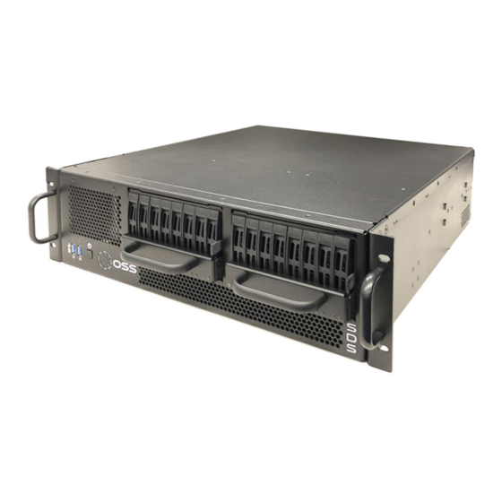
- Page 1 PCIe Gen 4 3U Short Depth AMD Server User Manual SKU: SDS-3U-4a www.onestopsystems.com...
-
Page 2: Table Of Contents
How to Update BMC Firmware via Web User Interface ....................26 How to Remove Power Supply Module .........................30 How to Remove Top Cover ............................31 How to Add / Remove PCIe Card ...........................32 M.2 Installation ................................33 Contacting Technical Support ............................34 Returning Merchandise to One Stop Systems ........................34 OSS-SDS-3U-4A... - Page 3 One Stop Systems Shipping / transporting the card ............................35 APPENDIX A Compliance .............................35 OSS-SDS-3U-4A...
-
Page 4: Preface
Disclaimer: We have attempted to identify most situations that may pose a danger, warning, or caution condition in this manual. However, One Stop Systems does not claim to have covered all situations that might require the use of a Caution, Warning, or Danger indicator. OSS-SDS-3U-4A... -
Page 5: Safety Instructions
Also, before connecting a cable, make sure both connectors are correctly oriented and aligned. CAUTION Do not attempt to service the system yourself except as explained in this manual. Follow installation instructions closely. OSS-SDS-3U-4A... -
Page 6: Protecting Against Electrostatic Discharge
Handle all sensitive components at an ESD workstation. If possible, use anti-static floor pads and workbench pads. Handle components and boards with care. Do not touch the components or contacts on a board. Hold a board by its edges or by its metal mounting bracket. OSS-SDS-3U-4A... -
Page 7: Product Information
PCIe Gen 4 server or form the core CPU and memory resources for a scale-out, rack level, expandable or composable solution in the shallowest available racks. The SDS-3U-4a features up to 7 PCIe Gen 4 x16 slots, and 16 SATA/SAS/NVMe drives. The server supports up to 2TB of memory per CPU socket and a resource expanded BIOS for scale-out device enumeration and large memory mapped I/O used for GPUs and accelerators. -
Page 8: Features
• System Monitoring • AC or DC Input Power Supplies • Resource expanded BIOS for large expansion capability • Guaranteed to operate with all OSS expansion products Overview Description OSS LOGO LED Power Button Front Handles Air Vent Drive-Pack #1... - Page 9 One Stop Systems Description Internal Fan Motherboard Storage Drives Controller IPMI Module Aux Power Connectors ATX Power Connector / Cable OSS-SDS-3U-4A...
-
Page 10: Motherboard Layout
One Stop Systems Motherboard Layout OSS-SDS-3U-4A... -
Page 11: Motherboard Descriptions
Clear CMOS Pad (CLRMOSl) PCIE2 xl6 Selection Jumper (PE16_SEL) PCIE2 x8 Selection Jumper (PE8_SEL) Thermal Sensor Header (TRI) TPM Header (TPMl) BMC SMBus Header (BMC_SMB1) Intelligent Platform Management Bus Header (IPMBl) CPU HP-SMBus Connector (CPU1_HSBP1) Non Maskable Interrupt Button (NMI_BTN1) OSS-SDS-3U-4A... - Page 12 Front Panel Type C USB 3.1 C,en2 Header (USB31_TC_2) 2x288-pin DDR4 DIMM Slots (DDR4.B1. DDR4_D1)** 2x288-pin DDR4 DIMM Slots (DDR4_Al. DDR4_Cl)“ TPM-SPI Header (TPM_BIOS_PH1) 2x288-pin DDR4 DIMM Slots (DDR4.E1, DDR4_G1)** 2x288-pin DDR4 DIMM Slots (DDR4_F1, DDR4_H1)** NVDIMM Power Support Jumper (NV12V_4) NVDIMM Power Support Jumper (NV12V_2) OSS-SDS-3U-4A...
-
Page 13: Setting Up
Connect the power cords. Press the front switch button to turn ON the unit. Upon powering ON the unit, the following LEDs will illuminate • LOGO will illuminate as sold blue. Power supply LEDs will illuminate as solid green. Blinking green, indicates the unit is on standby mode. OSS-SDS-3U-4A... -
Page 14: Log In
If only AMBER LEDs are illuminated, the IPMI module is malfunctioning, or the firmware is corrupted / not installed. ▪ To fix, send the unit to OSS for service to load the firmware on the IPMI module Log in You can log in to the Linux system using the following account cred... -
Page 15: Verify Pcie Cards / Devices
Two NVIDIA GPUs One Mellanox card One FPGA card (from HiTech Global) OSS-537 card (storage controller card). To check the OSS storage controller card (OSS-537): lspci -vvv | grep 02b2 To check the NVIDIA GPUs: #nvidia-smi. See output below OSS-SDS-3U-4A... - Page 16 To check on the NVME drive: #nvme -list. See sample output below. To check on Mellanox: #lspci | grep Mellanox To check on FPGA card from HiTech Global #lspci -s 01:00.0 | grep -i 19bb #lspci | grep 19bb OSS-SDS-3U-4A...
-
Page 17: Storage Drive Installation
Place the drive carrier on a flat sturdy surface. Remove the two mounting screws on both sides. Dismount the front handle to access the drive trays. Press the eject button, grasp the handle, and gently pull the drive tray out. OSS-SDS-3U-4A... -
Page 18: Install Storage Drive
Insert the drive tray into its bay vertically, keeping the carrier oriented so that the release button is on the bottom. Using the thumb, push against the lower part of the hard drive handle. Push the hard drive into the hard drive bay as illustrated below, until the hard drive clicks into the locked position. OSS-SDS-3U-4A... -
Page 19: Drive Slot & Link Status Leds
Drive Pack #1, occupied with 8 storage devices, LINK STATUS LEDs 0, 1, 2 and 3 are illuminated as solid green. Drive Pack #2, occupied with 8 storage devices, LINK STATUS LEDs 4, 5, 6 and 7 are illuminated as solid green. OSS-SDS-3U-4A... - Page 20 Drive Pack# 1, storage drive slots 1, 3, 5 and 7 are not connected to the LINK STATUS LED. No LINK STATUS LED associated with these drive slots will illuminate when drive is present except the LED located on the front OSS-SDS-3U-4A...
- Page 21 Drive Pack# 2, storage drive slots 1, 3, 5 and 7 are not connected to the LINK STATUS LED. No LINK STATUS LED associated with these drive slots will illuminate when drive is present except the LED located on the front. OSS-SDS-3U-4A...
-
Page 22: How To Access Motherboard Bmc Web Interface
Power up the SDS system, during boot up, the BMC IP address will show up on the screen, see photo below as example. Start your internet browser and enter the BMC IP address, see screenshot below: Login as “Admin,” password is “Admin” OSS-SDS-3U-4A... -
Page 23: How To Update Bios Via Ipmi Web User Interface
Cick BIOS Update This wizard will take you through the process of firmware upgrades. Click the “Browse to select the BIOS FW file. Then click “Start BIOS update” to start the upgrade process. Click OK if confirmed to continue the process. OSS-SDS-3U-4A... - Page 24 One Stop Systems FW verification processing, please wait a few second. Click “Proceed” to continue the BIOS FW upgrade process. Then click “OK” to start the actual BIOS FW upgrade operation. OSS-SDS-3U-4A...
- Page 25 One Stop Systems FW upgrade is processing, please wait a few second. BIOS FW upgrade process finished. Click “OK” to reload the webpage. NOTE: Clear the browser cookies after the BIOS FW upgrade process is finished. OSS-SDS-3U-4A...
-
Page 26: How To Update Bmc Firmware Via Web User Interface
One Stop Systems How to Update BMC Firmware via Web User Interface • Click Maintenance • Click Firmware update OSS-SDS-3U-4A... - Page 27 One Stop Systems This wizard will takes you through the process of firmware upgrades. Click the “Choose File” to select the BMC FW file. Then click “Start firmware update” for the upgrade process. FW verification processing, please wait a few second.. OSS-SDS-3U-4A...
- Page 28 One Stop Systems Click “Proceed” to continue the BMC FW upgrade process. Click “OK” to start the actual BMC FW upgrade operation. OSS-SDS-3U-4A...
- Page 29 One Stop Systems FW updrage is processing, please wait a few second.. BMC FW upgrade process finished. Click “OK” and reboot the system. Remark: Clear the browser cookies after the BMC FW upgrade process finished. OSS-SDS-3U-4A...
-
Page 30: How To Remove Power Supply Module
This section will demonstrate on how to dismount or detach the power supply Disconnect the power cord from the power supply Grasp the power-supply handle. Press the blue release latch (from right to left) and hold it. Pull the power supply out of the bay. OSS-SDS-3U-4A... -
Page 31: How To Remove Top Cover
After removing all the screws, stand at the front of the unit, place each hand on the side, both hands grasping the side of lid, push the lid to dislodge. Gently pull the lid from the back and lift it up OSS-SDS-3U-4A... -
Page 32: How To Add / Remove Pcie Card
Install your PCie card in the card slot. Place the card hold-down bracket on top of the card brackets and use two screws to secure it down. Remove the screws Detach the card-hold down bracket Install your PCIe card and secure it OSS-SDS-3U-4A... -
Page 33: Installation
One Stop Systems M.2 Installation OSS-SDS-3U-4A... -
Page 34: Contacting Technical Support
Returning Merchandise to One Stop Systems If factory service is required, you must contact OSS Service Representative to obtain a Return Merchandise Authorization (RMA) number. Put this number and your return address on the shipping label when you return the item(s) for service. One Stop Systems will return any product that is not accompanied by an RMA number. - Page 35 This Class A digital apparatus complies with Canadian ICES-003. Cet appareil numériqué de la classe A est conformé à la norme NMB-003 du Canada The product(s) described in this manual complies with all applicable European Union (CE) directives. One Stop Systems will not retest or recertify systems or components that have been reconfigured by customers OSS-SDS-3U-4A...
- Page 36 One Stop Systems 2235 Enterprise Street, Suite#110, Escondido CA 92029 Toll-Free : +1(800)285-8900 US • Main: +1 (760) 745-9883 • Fax: +1 (760) 745-9824 www.onestopsystems.com OSS-SDS-3U-4A...
Need help?
Do you have a question about the SDS-3U-4a and is the answer not in the manual?
Questions and answers