Table of Contents
Advertisement
Quick Links
Advertisement
Table of Contents

Related Manuals for Embention Veronte


Summary of Contents for Embention Veronte
- Page 1 Veronte-HUM-v2.8.docx pag: 1/20 Hardware User Manual...
-
Page 2: Table Of Contents
Veronte-HUM-v2.8.docx pag: 2/20 Table of Contents OVERVIEW ............................. 4 AIRCRAFT MOUNTING ........................5 2.1.1..........................5 NCLOSURE 2.1.2......................5 ECHANICAL OUNTING 2.1.3. Vibration Isolation ......................6 2.1.4. Location ..........................6 2.1.5. Orientation ......................... 6 2.1.6........................7 ONNECTOR AYOUT 2.1.7. - Page 3 Veronte-HUM-v2.8.docx pag: 3/20 8: E ........................12 ABLE XPANDER INTERFACE 9: J ..........................13 ABLE OYSTICK ONNECT 10: E ........................ 14 ABLE XTERNAL ADIO ONNECT 11: V ........................15 ABLE ERONTE PERFORMANCES Acronyms Analog to Digital Converter American Wire Gauge...
-
Page 4: Overview
4/20 1. Overview Veronte is the main element in our Flight Control System for UAS. As it can be seen in the diagram, Veronte hardware is used both in the ground segment (Ground) and onboard the UAV (either Air or Vision). -
Page 5: Aircraft Mounting
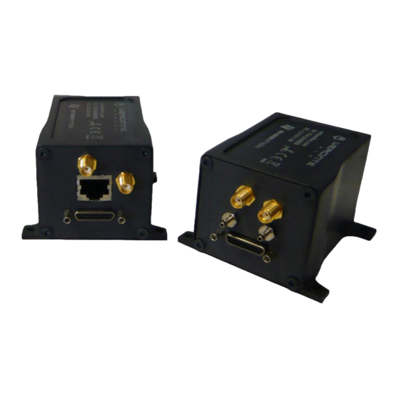
IP protection. The total weight including a 900 MHz / 2.4GHz radio module is 190g. Figure 2: Veronte Air All Veronte versionsshare thesame enclosure.Theonly differenceisthe distributionof the connectors onthepanel. Figure 3: Veronte dimensions (mm) 2.1.2. Mechanical Mounting screws recommended mounting. -
Page 6: Vibration Isolation
Veronte. Veronte can be mounted in different ways in order to reject the airframe vibration. The simplest could be achieved by just using a double-sided foam tape on the bottom side of Veronte. -
Page 7: Connector Layout
Index Connector RF antenna (SMA Jack Female) GPS antenna (SMA Jack Female) Ethernet (RJ-45) Veronte power and I/O (Micro-D) Static pressure port (Fitting 5/64in) Dynamic pressure port (Fitting 5/64in) Expansion board (Micro-D) Composite Video (SMA Jack Female) WIFI(SMA Jack Female) -
Page 8: Pressure Lines
Table 3: Antenna Installation 2.1.9. Pressure Lines Veronte has two pressure input lines, one for static pressure to determine the absolute pressure and one for pitot in order to determine the dynamic pressure. Absolute pressure connection on the aircraft is mandatory while pitot port can be obviated in some aircrafts, pitot port absence must be configured on Veronte Pipe software. -
Page 9: Electrical
Please read carefully the manual before powering the system. Veronte and servos can be powered by the same or different batteries, in case there is more than one battery on the system it is needed to ensurea singleunion of differentground. The ground signal should be isolated from other system ground references (e.g. -
Page 10: Veronte I/O Signals
Veronte-HUM-v2.8.docx pag: 10/20 3.1.2. Veronte I/O Signals Figure 8: 25-pin Micro D connector for Veronte Autopilot I/O(4) (Veronte connector view) Signal Input Output Comments Positive (+) 6.5 to 36V GND1 Negative (-) PWM/GPIO 1 5V (12mA) Veronte offers the option to directly drive up... -
Page 11: Vision I/O Signals
Veronte-HUM-v2.8.docx pag: 11/20 3.1.3. Vision I/O Signals Figure 9: 25-pin Micro D for Veronte Vision (7) (Veronte connector view) Different connections can be used depending on your camera configuration. Signal Input Output Comments POWER POWER RS_232_OUT COMMUNICATION BUS RS_232_IN... -
Page 12: Expander I/O Signals
Veronte-HUM-v2.8.docx pag: 12/20 3.1.1. Expander I/O Signals Figure 10: 25-pin Micro D for Veronte Expander (7) (Veronte connector view) Different connections can be used depending on theselected hardware configuration. Signal Input Output Comments RS-232_A_TX RS-232_A_RX PWM5/ECAP3 Hardware option, not selectable on SW... -
Page 13: Joystick
Veronte-HUM-v2.8.docx pag: 13/20 3.1.2. Joystick To connect the joystick to the system, use the DIGIN1port on Veronte Ground connected to the radio trainer port. Veronte is compatible with standard PPM signals, Futaba radios between 8 and 12 channels are recommended. -
Page 14: External Radio
Veronte-HUM-v2.8.docx pag: 14/20 3.1.3. External Radio Veronte is also offered with a RS-232 connector to be used with an external radio. Figure 13: External Radio Connector The mating radio connector for this configuration is: Phoenix Contact - 1681172 Signal Input... -
Page 15: Performances
Datalink X-868 MHz ISM / Range 40km / 4 Kbps X-902 to 928 MHz / Range 45km / 10 kbps Table11: Veronte performances No convection, ask for increased limits (up to 71ºC) Ask for increased limits (up to 50kPa) Ask for increased limits (up to IP67) Limit for sustained maneuvers. -
Page 16: Troubleshooting
Veronte-HUM-v2.8.docx pag: 16/20 5. Troubleshooting I´m having problems with the GPS signal o Reduce noise level on the GND connection on the autopilot by connecting the autopilot GND directly to the battery GND, avoiding intermediate connections and solders. -
Page 17: Annex 1: Connector Colour Code
Veronte-HUM-v2.8.docx pag: 17/20 6. Annex 1: Connector Colour Code Micro-D connector Molex 83424-9019... -
Page 18: Annex 2: Connexion Example - Multicopter
Veronte-HUM-v2.8.docx pag: 18/20 7. Annex 2: Connexion example – Multicopter Pin 14 – V+ Battery Pin 15 – V- Pin1 – CH1 ESC 1 Pin 2 – CH2 ESC 2 Pin 3 – CH3 ESC 3 Pin 4 – CH4... -
Page 19: Annex 3: Connexion Example - Fixed Wing
Veronte-HUM-v2.8.docx pag: 19/20 8. Annex 3: Connexion example – Fixed wing Pin 14 – V+ Pin 15 – V- Battery Pin1 – CH1 Aileron right Pin 5 – CH5 Aileron left Pin 2 – CH2 Elevator Pin 4 – CH4 Rudder Pin 6 –... -
Page 20: Annex 3: Connexion Example - Helicopter
Veronte-HUM-v2.8.docx pag: 20/20 9. Annex 3: Connexion example – Helicopter Pin 14 – V+ Pin 15 – V- Battery Pin1 – CH1 Plate NW Pin 5 – CH5 Plate S Pin 2 – CH2 Plate NE Pin 4 – CH4 Tail Pin 12 –...
Need help?
Do you have a question about the Veronte and is the answer not in the manual?
Questions and answers