Table of Contents
Advertisement
Advertisement
Table of Contents

Subscribe to Our Youtube Channel
Related Manuals for Embention Veronte 4


Summary of Contents for Embention Veronte 4
- Page 1 Veronte-4-HUM.docx pag: 1/20 Hardware User Manual Veronte 4...
-
Page 2: Table Of Contents
cod: Veronte-4-HUM.docx pag: 2/20 Table of Contents OVERVIEW ............................. 5 ............................ 5 PERATION ............................ 5 LATFORMS SAFETY ............................7 AIRCRAFT MOUNTING ........................7 ............................ 7 NCLOSURE OEM ............................8 ......................... 9 ECHANICAL OUNTING 3.3.1 Vibration Isolation ........................9 3.3.2 Location ..........................10 3.3.3 Orientation ........................... - Page 3 cod: Veronte-4-HUM.docx pag: 3/20 Acronyms Analog to Digital Converter American Wire Gauge Capture Module Direct Current DGPS Differential GPS Digital Transmission System ECAP Enhanced CAP EGNOS European Geostationary Navigation Overlay Service EPWM Enhanced PWM Flight Control System FHSS Frequency Hopping Spread Spectrum Flight Termination System Geographical Information System Ground...
- Page 4 cod: Veronte-4-HUM.docx pag: 4/20 CHANGES RECORD Issue Date Change description 10/04/2017 Initial Issue document 15/05/2017 Safety information added Digital inputs voltage range 19/05/2017 changed. 20/09/2017 Mechanical drawing updated. 25/09/2017 Table 1 updated 20/12/2017 Section 4.4 added. 21/12/2017 Errata correction on section 4.4 Power and torque updated.
-
Page 5: Overview
cod: Veronte-4-HUM.docx pag: 5/20 1. Overview Veronte Autopilot is a miniaturized high reliability avionics system for advanced control of unmanned systems. This control system embeds a state-of-the-art suite of sensors and processors together with LOS and BLOS M2M datalink radio, all with reduced size and weight. 1.1 Operation The unique Plug ´n Fly control system, Veronte Autopilot ads fully autonomous control capabilities to any unmanned system for complete operation, compatible with: UAV, Drone,... -
Page 6: Figure 1: Veronte Fcs Overview
cod: Veronte-4-HUM.docx pag: 6/20 Figure 1: Veronte FCS Overview Veronte contains all the electronics and sensors needed in order to properly execute all the functions needed to control the UAV. A Veronte-based FCS contains the following elements: Veronte (Air): it executes in real time all the guidance, navigation and control algorithms ... -
Page 7: Safety
cod: Veronte-4-HUM.docx pag: 7/20 2. Safety Veronte autopilot includes the following features in order to provide your UAS with the best safety performances: Redundant IMU. • • Redundant GPS receiver. • Redundant Pressure sensor. Dual core principal microprocessor + dissimilar safety microcontroller (comicro). •... -
Page 8: Oem
cod: Veronte-4-HUM.docx pag: 8/20 Figure 3: Veronte dimensions (mm) 3.2 OEM Veronte can be provided in OEM version too. The total approximate weight is 90g. Figure 4: Veronte OEM dimensions (mm) -
Page 9: Mechanical Mounting
cod: Veronte-4-HUM.docx pag: 9/20 3.3 Mechanical Mounting M4 screws are recommended for mounting. Figure 5: Veronte dimensions (mm) Vibration Isolation Although Veronte ultimately rejects noise and high-frequency modes of vibration with electronic filters and internal mechanical filters, there might be situation where external isolation components might be needed. -
Page 10: Location
cod: Veronte-4-HUM.docx pag: 10/20 The user should take into account that wiring should be loose enough so vibrations may not be transmitted to Veronte. In cases where Veronte isolation is not viable, it is possible to use soft engine mounts. It is also recommended when there are other sensible payloads like video cameras or for high vibration engines. -
Page 11: Mating Connectors
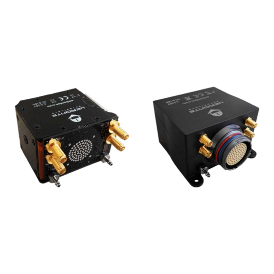
cod: Veronte-4-HUM.docx pag: 11/20 Index Connector LOS SSMA connector GNSS1 SSMA connector M2M SSMA connector GNSS2 SSMA connector Static pressure port (Fitting 5/64in) Dynamic pressure port (Fitting 5/64in) 68-pin connector Table 1: Veronte connection panel For both pressure ports, mating with clamped 2mm internal diameter flexible tubing is recommended. -
Page 12: Pressure Lines
cod: Veronte-4-HUM.docx pag: 12/20 3.7 Pressure Lines Veronte has two pressure input lines, one for static pressure to determine the absolute pressure and one for pitot in order to determine the dynamic pressure. Absolute pressure connection on the aircraft is mandatory while pitot port can be obviated in some aircrafts. -
Page 13: Veronte I/O Signals
cod: Veronte-4-HUM.docx pag: 13/20 4.2 Veronte I/O Signals Figure 9: 68-pin redundant connector for Veronte Autopilot (frontal view) 68-PIN CONNECTOR SIGNAL TYPE COMMENTS I/O1 PWM/DIGITAL OUTPUT/DIGITAL INPUT SIGNAL (0-3.3V) I/O2 PWM/DIGITAL OUTPUT/DIGITAL INPUT SIGNAL (0-3.3V) I/O3 PWM/DIGITAL OUTPUT/DIGITAL INPUT SIGNAL (0-3.3V) I/O4 PWM/DIGITAL OUTPUT/DIGITAL INPUT SIGNAL (0-3.3V) I/O5... - Page 14 cod: Veronte-4-HUM.docx pag: 14/20 23 ANALOG_5 INPUT ANALOG INPUT 0-3V 24 GND GROUND GROUND SIGNAL FOR BUSES 25 CANA_P CANbus interface. It supports data rates up to 1 Mbps. 26 CANA_N Twisted pair with a 120Ω Zo recommended 27 GND GROUND GROUND SIGNAL FOR BUSES 28 CANB_P...
-
Page 15: Harness Colour Code
cod: Veronte-4-HUM.docx pag: 15/20 66 GND GROUND VERONTE GROUND INPUT 67 VCC2 POWER VERONTE POWER SUPPLY (6.5 to 36V) 68 VCC1 POWER VERONTE POWER SUPPLY (6.5 to 36V) Table 5: Veronte I/O interface 4.3 Harness colour code 68-PIN CONNECTOR COLOUR Description CODE Black... -
Page 16: Joystick
cod: Veronte-4-HUM.docx pag: 16/20 WT GN Table 6: Colour code 4.4 Joystick To use the joystick in the system, connect the PPMout of the trainer port to a digital input of Veronte and configure that digital input as the radio input in Pipe. If the PPM level is 3.3V, pins 1-8, 10-17 and 55-58 pins can be used. -
Page 17: Figure 10: Futaba T10 Joystick
cod: Veronte-4-HUM.docx pag: 17/20 Veronte is compatible with standard Pulse Positon Modulation (PPM) signals, Futaba radios between 8 and 12 channels are recommended. Figure 10: Futaba T10 Joystick Figure 11: PPM Signal As default, channel 8 is reserved for manual / auto switch. High level is used for automatic flight and low level for manual control. -
Page 18: Oem Board Pinout
cod: Veronte-4-HUM.docx pag: 18/20 4.5 OEM Board Pinout Figure 13: OEM Board Figure 14: Pinouts for OEM Board PINOUT SIGNAL TYPE COMMENTS LOS SSMA CONNECTOR GNSS1 SSMA CONNECTOR M2M SSMA CONNECTOR GNSS2 SSMA CONNECTOR STATIC PRESSURE PORT (FITTING 5/64IN) DYNAMIC PRESSURE PORT (FITTING 5/64IN) 7C to 28C GROUND GROUND SIGNAL SIGNAL FROM COMICRO TO ACTIVAE SAFETY... -
Page 19: T Able 7: Oem Board Pinout
cod: Veronte-4-HUM.docx pag: 19/20 IN_485_P NON-INVERTED INPUT FOR RS-485 BUS IN_485_N INVERTED INPUT FOR RS-485 BUS OUT_485_N INVERTED OUTPUT FOR RS-485 BUS OUT_485_P NON-INVERTED OUTPUT FOR RS-485 BUS SDA_A_OUT DATA SCL_A_OUT CANA_P CANbus interface. It supports data rates up to 1 Mbps. CANA_N Recommended cable is a twisted pair with a 120Ω... -
Page 20: Performances
cod: Veronte-4-HUM.docx pag: 20/20 5. Performances Variable Value Weight (with enclosure and connector) 190g Weight (OEM) Voltage Input 6.5V to 36V 5W without M2M Power Input 9W with 3.75G M2M 15Wmax with 2G M2M Minimum Temperature -40ºC Maximum Temperature +55ºC Max.
Need help?
Do you have a question about the Veronte 4 and is the answer not in the manual?
Questions and answers