Advertisement
Quick Links
Quick Installation Guide
Industrial 28G L2+/L3 Rackmount
Managed Ethernet Switch
8028GX8-AC2
www.avcomm.cn
・Overview
8028GX8 is an industrial grade rackmount 28G switch with 20 Giga
copper ports, 4 Giga combo ports and 4 100M/1G fiber SFP slots.
Rugged design, cyber security features and high EMC immunity
makes the 8028GX8 an ideal solution for industrial control room,
roadside traffic control, industrial IoT, industrial Surveillance
applications.
Model Name
Description
Industrial 28G L2+ Managed Ethernet Switch,
8028GX8-AC2
20GT+4Gc+4GF, 2x AC110/220V input
Industrial 28G L3 Managed Ethernet Switch,
8028GX8-L3-AC2
20GT+4Gc+4GF, AC110/220V input
・Package Checklist
•
1 x Product Unit
•
1 or 2 x Power Cord (AC model only, EU or US type)
•
1 x Quick Installation Guide
Optional Accessory (for detailed information please refer to the
Datasheet):
•
1 Gbps SFP Transceiver
AVCOMM Technologies, Inc
・Installation Procedure
Installing in a Rack
Refer to the illustrations below; user can install the device in most
standard 19-inch (48.3-cm) racks. For RS628/428 2 power series,
user should use the 4 of supplied screws to attach a mounting bracket
on each side of device first.
•
Insert and tighten two screws through each of the mounting
brackets.
Mounting Bracket Hole
Mounting Bracket Hole
Mounting ear and screws for
RS628/428 2 Power series
Wiring the Digital Input
To wire the DI on the Terminal block, use
screwdriver to loosen screws, insert the positive
and negative wires into the DI+ and DI- contact
and then tighten screws after the DI wire is
connected. High: 11~30V, Low: 0~10V.
Wiring the Relay Output (Alarm)
The relay output of the 2-pin terminal block
connector are used to detect user-configured
events. The two wires attached to the fault
contacts form a close circuit when a user-
configured event is triggered. If a user-configured
event does not occur, the fault circuit remains
open. The spec. of DO is 0.5A/24VDC.
Wiring the Power Input
Connect the attached power to the AC or DC power input connector, the
available AC power input range is from 90-264 VAC while the DC power
input range is
18~72VDC.
Grounding Screw
For avoiding system damage by noise or electric shock, establish a direct
connection between the ground screw and the grounding surface prior to
connecting devices. At the AC power input, the 3 pin include V+, V- and
GND. For DC version, the grounding screw is on the right side of DC
power connector. The GND pin must be connected to the earth ground.
USB Port
Use the USB port in order to save or restore
the configuration and upload the firmware
upgrade file.
For further configurations, please refer to User
Manual.
Combo Port Mode
The device supports 4 Combo ports and allow user to configure 3 types
of port modes in the following path.
Ethernet Port -> Port Setting -> Port Mode
Select the Port Mode type and press "Submit". After submitted, Reboot
the system to activate the new setting.
For further configurations, please refer to User Manual.
20GbE Copper + 8 GbE Fiber (Default)
24GbE Copper + 4 GbE Fiber
22GbE Copper + 6 GbE Fiber
DI
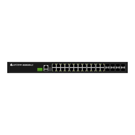
・Appearance
Front view
8028GX8-AC2
System LED
• 2 x Power
DO
• 1 x System Status
• 1 x DI
• 1 x Alarm
• 1 x Ring Status
Integrated DI/DO Connector
• 1 x 4 pin terminal block
2 pin for DI
2 pin for DO
Rear view
Console
2 AC Power for
115,200,
8028GX8-AC2
N,8,1
USB
Port Mode
COMBO Port 21-24
4 x Fiber
4 x Copper
2 x Copper+2 x Fiber
• 4-port 100/1000M
RJ45/SFP combo
(configured by UI)
• 20-port 100/1000MBase-T
Easy System Management
SFP Port
• USB for
• 4-port
Configuration/Firmware
100M/1G
update
SFP
• RS232 Console
Mounting Bracket
2 power model series
will be as accessory
www.avcomm.cn
Advertisement

Related Manuals for AVCOMM 8028GX8-AC2


Summary of Contents for AVCOMM 8028GX8-AC2
- Page 1 1 or 2 x Power Cord (AC model only, EU or US type) upgrade file. • 1 x Quick Installation Guide For further configurations, please refer to User Optional Accessory (for detailed information please refer to the Manual. Datasheet): • 1 Gbps SFP Transceiver AVCOMM Technologies, Inc www.avcomm.cn...
- Page 2 Ring is disabled PC is located in the same subnet (192.168.10.x). AVCOMM reserves the right to make changes to this QIG or to the Any failures in port link, ping, product hardware at any time without notice. It is the user’s responsibility...
Need help?
Do you have a question about the 8028GX8-AC2 and is the answer not in the manual?
Questions and answers