
Related Manuals for LAWO Power Core


Summary of Contents for LAWO Power Core
- Page 1 Power Core User Manual Version: 6.6.0/3 Edition: Tuesday, June 8, 2021 To obtain the latest documentation and software downloads, please visit: www.lawo.com/lawo-downloads...
- Page 2 All rights reserved. Permission to reprint or electronically reproduce any document or graphic in whole or in part for any reason is expressly prohibited, unless prior written consent is obtained from the Lawo All trademarks and registered trademarks belong to their respective owners. It cannot be guaranteed that all product names, products, trademarks, requisitions, regulations, guidelines, specifications and norms are free from trade mark rights of third parties.
-
Page 3: Table Of Contents
4. The Hardware ............................. 7 5. Licensed Feature Sets ........................14 6. Installation ............................19 7. System Setup ............................ 36 8. Configuring Power Core ........................52 9. Audio IO ............................64 10. Audio Mix Engine ..........................94 11. Audio Utilities ........................... 165 12. -
Page 4: Introduction
Power Core can be installed as a stand-alone device, or as the integrated DSP Core for a Lawo control surface. If installing with a control surface, you will find more information on the surface components in the relevant manual. -
Page 5: Important Safety Instructions
2. Important Safety Instructions Important Safety Instructions Please observe all of the instructions provided in the "General Safety Information for Lawo Equipment" booklet delivered with your devices. Double-click here to open the information as a pdf. Power Core User Manual Version: 6.6.0/3... -
Page 6: Product Overview
Remote Control If Power Core is connected to a control surface (via the CAN bus), then all resources can be controlled from the console. In addition, Power Core supports a range of remote control options (via TCP/IP) including VisTool MK2 and Ember+. -
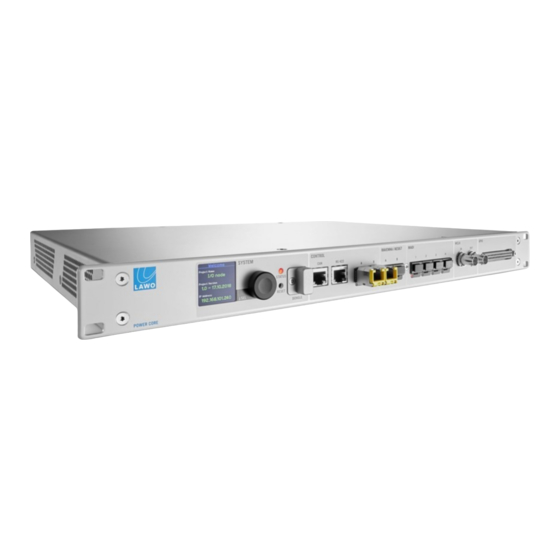
Page 7: The Hardware
4. The Hardware The Hardware This chapter describes the hardware components and options. Topics include: · Front View · Rear View · The Front Panel Display · The STATUS LED · IO Cards Power Core User Manual Version: 6.6.0/3 7/539... - Page 8 Audio Workstation and for debugging. It is usually left unconnected. CONTROL A & B (via SFP) The two CONTROL ports connect other devices to the Power Core control system. Applications include remote control via TCP/IP; networking to other products; updating firmware and uploading a configuration.
- Page 9 This connector provides 8 x GPI (optocouplers) and 8 x GPO (silent and self-healing relays) for local signaling and switched functions. For Power Core Edge or Super Audio Node, you must purchase the GPIO add-on license to activate these signals.
- Page 10 The 955/50-80 power supply can be ordered separately. If both inputs are connected, then AC provides the main and DC the redundant power supply. Power Core MUST be connected to the mains using the power cable supplied with the system. 10/539 Version: 6.6.0/3...
- Page 11 Identifying a Power Core The "Identify" function can be used to send a message to the front panel display so that a Power Core can be easily identified. The message can be sent in one of three ways: ·...
- Page 12 If the LED is blinking at regular intervals, then the device is working properly and the LED indicates the sync status. Note that if the LED is blinking from white to a color, then this indicates that Power Core is running as a PTP Master. The table below describes the possible states:...
- Page 13 2 x RJ45 channels in total with SRC) *All DB-25 connectors are wired according to the AES59 (TASCAM) standard, except for the Headphone outputs on the STUDIO IO card. See Connector Pin-Outs for wiring information. Power Core User Manual Version: 6.6.0/3 13/539...
-
Page 14: Licensed Feature Sets
5. Licensed Feature Sets Licensed Feature Sets This chapter describes the licensing options. Topics include: · Introduction · Power Core License Chart · Preparing a Configuration 14/539 Version: 6.6.0/3 Power Core User Manual... - Page 15 Power Core Max This is identical to the Radio Console XL package but adds the ability to control Power Core from up to four independent surfaces. The connected surfaces share the Power Core Max resources. Thus, they can be any permitted size and layout as long as the total number of resources do not exceed those given in the license chart.
- Page 16 The resource numbers listed in the chart are the mono equivalent. All of the main license packages allow sources and buses to be grouped into stereo bundles. If you wish to group in 5.1 bundles, then you will need to purchase either a "Radio Console XL" or "Power Core Max" license. 16/539 Version: 6.6.0/3...
- Page 17 Preparing a Configuration When installing a new license or add-on, it is important that the ON-AIR Designer configuration is prepared correctly. Otherwise the features defined by the configuration will not work, and the Power Core license alarm will sound every few seconds! How to configure Power Core is described later.
- Page 18 If an add-on license is available, then its features can be enabled (or disabled) by right-clicking on the 'System Core' element. For example: To enable the GPIOs for Power Core Edge or Super Audio Node, right-click on the GPIO connector: To enable the Loopbacks (LB), Minimixer (MM) or N-1 features, right-click on the option printed on the DONGLE icon: In each case, the license status is indicated by the text color: red = enabled;...
-
Page 19: Installation
· Unpacking · Packing List · Mounting the Frame · Dimensions and Weight · Temperature and Cooling · Fitting the IO Cards · SFP Modules · Grounding & Power · Wiring · Synchronization Power Core User Manual Version: 6.6.0/3 19/539... - Page 20 Unpacking Power Core is delivered in its own box with all accessories. If you have ordered IO cards for the rear expansion slots, SFP modules or a 12V DC power supply, then these will be packaged separately (in the same box).
- Page 21 Dust caps for the Network Interface and MADI SFP cages - these will be mounted in the frame. · 1 x USB memory card - containing marketing materials. Note that the Power Core license code (for the USB dongle) can be found on the delivery note. Optional The following items must be ordered separately: ·...
- Page 22 Adapters Rear View Power Core is designed to be mounted in a 19-inch rack. Please install supporting slide bars to hold the weight of the unit, and use the locking devices provided. For recessed rack-mounting, use standard, third-party, 1RU recessed rack adapters such as the ones shown above. When fitting the rack adapters and slide bars, you must make sure that there is sufficient airflow around the device for cooling.
- Page 23 6. Installation Dimensions and Weight Width 483 mm (19”) Height 44.0 mm (1 RU) Depth (inc locking devices) 385 mm Weight (without expansion IO cards) 4.5 kg dimension drawing is included in the Appendices. Power Core User Manual Version: 6.6.0/3 23/539...
- Page 24 6. Installation Temperature and Cooling Power Core is equipped with temperature-controlled fans for minimum noise emission. Ventilation holes are provided on the left and right. There must be sufficient airflow around the device for cooling. DO NOT obstruct the side ventilation holes as to do so will prevent efficient cooling.
- Page 25 Rear Panel Expansion Slots "Empty" Example Configuration Power Core is delivered with a metal cover plate fitted to each expansion slot. To use your IO cards, they must be installed into the frame. Cards can be installed in any slot position as long as the frame meets the requirements stated earlier (i.e.
- Page 26 When you have fitted all the IO cards for your system, check that all cards are screwed into the frame and that any empty slots are closed with metal cover plates. The installation is now complete, and you can wire your audio devices to the IO card connectors. 26/539 Version: 6.6.0/3 Power Core User Manual...
- Page 27 SFP Modules To use a CONTROL, RAVENNA/AES67 or MADI port, you must fit an SFP module. All SFPs must be Lawo- certified (as listed below). SFPs are not included and must be ordered separately. You will need one SFP for each port.
- Page 28 DC IN connector on the rear of the frame. Using a M4x8 screw, fasten the grounding cable to the CASE bolt. If installing Power Core with a control surface, then establish a direct connection to the control surface modules using the CAN bus.
- Page 29 6. Installation 6.8.2 Power Power Core comes with dual power feeds: AC and DC. If both inputs are connected, then the two feeds provide main and redundant power. AC Input The frame includes an integrated wide-ranging AC power supply, and is delivered with a 2m IEC power cable (country-specific).
- Page 30 Power Core (front and rear) CAN (CAT 5e) If Power Core is installed with a control surface, then the CAN bus connects Power Core to the control surface frames. If there are no control surface components, then this connector is unused.
- Page 31 The two RAVENNA/AES67 interfaces connect the AoIP streams to the IP network. The total Audio over IP capacity of one Power Core is up to 256 IO channels depending on the license purchased. This can be split into up to 128 streams, where each stream can be mono, stereo or multi-channel.
- Page 32 · GPO = 8 x Opto-MOS relays (50V AC / 120mA @ 50V) The connector is a 37-pin D-type. For Power Core Edge or Super Audio Node, you must purchase the GPIO add-on license to activate these signals. 32/539 Version: 6.6.0/3...
- Page 33 (CAT 5e/6/7); straight or crossed Ethernet cable. The supported standard is Gigabit Ethernet (1000 Base-Tx). The maximum cable length is up to 80m. The configuration of the DANTE Brooklyn II modules depends on their firmware version. Please refer to your Lawo software release notes for the latest information. For more information about DANTE networking, please refer to https://www.audinate.com.
- Page 34 Each of the external sync options listed above can be independently enabled or disabled by the configuration. If disabled, Power Core will ignore the sync source even if it receives a valid signal. It is possible to enable one or multiple sync options for the device.
- Page 35 The Prio Sequence box shows the priority of the external sync sources as defined by the configuration - in our example, PTP, Wordclock and then MADI. 6.10.3 Sync Output The front panel WCLK OUT connector always provides an output of the current system reference. Power Core User Manual Version: 6.6.0/3 35/539...
-
Page 36: System Setup
· Updating the Firmware · Uploading a Configuration · Activating the Licenses · Editing the System IP Settings · Setting the System Date and Time · Setting the Time Zone · Network Security 36/539 Version: 6.6.0/3 Power Core User Manual... - Page 37 7. System Setup System Connections (Required for Setup) In order to boot and configure Power Core, the following connections must be made: Ethernet to the configuration PC and AC power. If you are planning to connect a control surface, then please also refer to Connecting a Control Surface.
- Page 38 It means that when you turn on, you will get back to wherever you were at the last power off. The last known PTP Master/Slave mode may not be reinstated if Power Core is set to operate as PTP Slave only.
- Page 39 To establish a network connection to Power Core, you will need to configure the network settings for the PC's LAN port. The exact steps vary depending on your OS version. The IP Address must be unique, and set within the same range as that of Power Core's CONTROL A port. The Subnet Masks should be identical.
- Page 40 It is recommended to leave the default "Run" options selected and click on Finish. You can now use SoP Explorer to check the firmware revisions of the system, and ON-AIR Designer to transfer a configuration. If you have any problems with the software installation, please contact your local Lawo representative or email support@lawo.com.
- Page 41 Updating the Firmware Once all of the system components are connected and powered, you should check their firmware revisions using SoP Explorer. The screenshots below are taken from Power Core, but the procedure is identical for all radio on-air systems.
- Page 42 Continue to start the update - the progress is shown in the status bar. An update can take several minutes. Once the update is complete, Power Core will cold start. Wait for the system to reboot and then click on the refresh button to update the "Status"...
- Page 43 (after Login). This can be modified later if you wish. The screenshots below are taken from Power Core, but the procedure is identical for all on-air systems. ON-AIR Designer starts automatically at the end of the software installation procedure.
- Page 44 7. System Setup Activating the Licenses The Power Core main license plus any add-ons must be installed onto the USB memory stick supplied with the system and connected to the front panel DONGLE port. The licenses are activated and managed by the...
- Page 45 To use this method, your PC must have an internet connection. If installing onto a dongle, then this should be connected to the PC's USB port. Open the Lawo licensing web page by copying the following URL into your web browser: https://licenseportal.lawo.com If necessary you can choose a different language using the drop-down menu at the top right of the page.
- Page 46 After selecting OK, a summary appears: You can now close the browser and return to your Lawo software application or install the USB dongle. For information on re-hosting a license, offline activation, backup/restore and using a license server, please...
- Page 47 7.6.5 Installing the License Dongle Once the Power Core licenses have been activated, connect the USB memory stick to the DONGLE port on the front panel: If the optional safety cap is fitted, you will need a T10 star tool to remove and replace the cap.
- Page 48 Editing the System IP Settings If you are installing Power Core into a network with other devices, then you will need to edit the IP settings of the Power Core's CONTROL A port. This can be achieved by opening a Web UI session as follows.
- Page 49 PC before you begin. Start the application by selecting START -> Program Files -> SoP Explorer. Select Unit -> New... from the main menus, enter the IP address of Power Core and select OK to add the unit. SoP Explorer connects to Power Core and analyses the current firmware revisions.
- Page 50 7. System Setup Setting the Time Zone The time zone can be edited by opening a Web UI session to Power Core. Open the Web UI and login as Supervisor (default password = orion). Select the System -> Information page.
- Page 51 This option allows you to use a secure connection for the Web UI. It can be achieved by storing the required SSL certificates on the Power Core device. The steps required to prepare the device are described later. Once the certificates are in place, the Web UI can be opened using a "https" connection. Apart from the connection method, there is no difference in the functionality.
-
Page 52: Configuring Power Core
8. Configuring Power Core Configuring Power Core This chapter describes how to configure Power Core. You should be familiar with the ON-AIR Designer configuration tool. If not, please refer to the separate "ON-AIR Designer User Guide". Topics include: · Starting a Configuration ·... - Page 53 A copy of the project file can be stored on the Power Core device. In this instance, you can download a copy to your computer using 'Load Project from unit'.
- Page 54 The specification can be changed later (via Frame -> Change Frame). So, for example, if you purchase a new main license package for Power Core, you can change the System Core frame to unlock the additional resources. 54/539 Version: 6.6.0/3...
- Page 55 8. Configuring Power Core Once you have specified the 'Frame' , click on Finish. The software creates the new project and a number of windows will open. In our example, we can see the 'Project' window (on the left), plus the 'System Core' (in the central working area): It may take a few seconds to build the new project.
- Page 56 If you see an error stating that the project is already open then navigate to the project folder (using Windows Explorer) and delete any "projectname.txt" files. Then try opening the project again. On Power Core and Nova17, a copy of the project file is stored on the DSP Core. To download it to your computer, use Load Project from unit.
- Page 57 8. Configuring Power Core Checking the Network Communication You can check the network connection to the Lawo system by opening a project and ticking the Online checkbox. The two indicators show the connection status: green = valid connection; red = not connected; yellow = the device firmware needs updating.
- Page 58 8. Configuring Power Core Loading a Project from the Unit For Power Core and Nova17, a copy of the project file is stored on the DSP Core. This allows you to download it onto your computer at a later time.
- Page 59 8. Configuring Power Core Selecting a Different License Package The 'Change Frame' window can be used to change the maximum specification of the system. Select Frame -> change frame to open the window. Here you can change the specification of any component: System Core, Surface, Panels or Screen.
- Page 60 If an add-on license is available, then its features can be enabled (or disabled) by right-clicking on the 'System Core' element. For example: To enable the GPIOs for Power Core Edge or Super Audio Node, right-click on the GPIO connector: To enable the Loopbacks (LB), Minimixer (MM) or N-1 features, right-click on the option printed on the DONGLE icon: In each case, the license status is indicated by the text color: red = enabled;...
- Page 61 8. Configuring Power Core Monitoring the Resources The 'Resources' window can be used to check the DSP resources used by the project. Select Command -> Resources to open the window. The counters show how many resources are left out of the maximum available. The maximum numbers vary depending on the main license.
- Page 62 At regular intervals you should save the project, and also use "save as" to keep a copy of the project at different revision stages. This will allow you to test the configuration and revert to an earlier version if necessary. The screenshots below are taken from Power Core, but the procedure is identical for all on-air systems. Ø...
- Page 63 Transferring Configuration Data to the Unit This function transfers the configuration parameters to the selected unit. The screenshot below is taken from Power Core, but the procedure is identical for all radio on-air systems. Start by opening the project you wish to transfer.
-
Page 64: Audio Io
9. Audio IO Audio IO This chapter describes how to configure the audio IO. Topics include: · Setting Up IO Cards · Setting Up MADI · Setting Up RAVENNA/AES67 · Setting Up Synchronisation 64/539 Version: 6.6.0/3 Power Core User Manual... - Page 65 System Core Configuration The 'System Core' configuration defines the plug-in cards and IO parameters for the DSP Core. The example below describes Power Core. Other cores are configured in a similar manner. Click on the Toolbar icon, or select Frame -> System Core, to open the window.
- Page 66 The IO parameters are organized per card/connector. The topics which follow describe the parameters for each type of signal. Parameters can also be edited in list form using 'Command -> Inputs' or 'Command -> Outputs'. 66/539 Version: 6.6.0/3 Power Core User Manual...
- Page 67 MtxCon (NovaConnect) software. · LS - sets the input for control from the optional Line Scheduler (LS) product. Please contact your local Lawo representative for details. · OFF – the input is not enabled for external matrix control.
- Page 68 Use the Type and Stereo fields to set the format of the input (as described earlier). Offset Gain Here you can enter a fixed analog offset gain for the input. Matrix Enable This option enables matrix control of the input (as described earlier). 68/539 Version: 6.6.0/3 Power Core User Manual...
- Page 69 Default Audio assignments if they are overridden during operation of the system. A Default Audio source cannot be assigned if Matrix Enable is active. Power Core User Manual Version: 6.6.0/3 69/539...
- Page 70 If the option is enabled, you cannot use the Default Audio function. Default Audio Double-click in the Default Audio box to assign a default audio source for the output (as described earlier). Phones Parameters These parameters are identical to the output parameters described above. 70/539 Version: 6.6.0/3 Power Core User Manual...
- Page 71 This option enables matrix control of the output (as described earlier). If the option is enabled, you cannot use the Default Audio function. Default Audio Double-click in the Default Audio box to assign a default audio source for the output (as described earlier). Power Core User Manual Version: 6.6.0/3 71/539...
- Page 72 Select this checkbox to set the output to be “transparent”. The option should be enabled if you are using the output to route a Dolby E signal. Default Audio Double-click in the Default Audio box to assign a default audio source for the output (as described earlier). 72/539 Version: 6.6.0/3 Power Core User Manual...
- Page 73 9. Audio IO MADI Settings On Power Core, the following parameters configure the MADI ports on plug-in IO cards. The same settings for other MADI ports can be accessed via the "System -> Definition -> Parameter = MADI" branch of the 'Tree Definition'.
- Page 74 9. Audio IO Module Parameters All IO cards in Power Core include a Module tab which can include either one or two options. Ignore Card This option is available for all plug-in IO cards. If enabled, the IO card is ignored by the system alarm (monitored via the Web UI or alarm bus).
- Page 75 This option enables matrix control of the input (as described earlier). Transparent Select this checkbox to set the input to be “transparent”. The option should be enabled if you are using the input to route a Dolby E signal. Power Core User Manual Version: 6.6.0/3 75/539...
- Page 76 Select this checkbox to set the output to be “transparent”. The option should be enabled if you are using the output to route a Dolby E signal. Default Audio Double-click in the Default Audio box to assign a default audio source for the output (as described earlier). 76/539 Version: 6.6.0/3 Power Core User Manual...
- Page 77 To configure redundant MADI outputs, check the P2 Tx=P1 Tx option. Now MADI port P2 transmits the same data as port P1. You can use this procedure to configure each odd/even pair of MADI ports. Power Core User Manual Version: 6.6.0/3 77/539...
- Page 78 Multicast address schema, default or predefined? Stream routing control, internal or external controller such as VSM? 4. Configuration and License Requirements – POWERCORE licensing, stream configuration. Power Core License: Edge, SAN, L, XL or MAX? Power Core IO matrix, stereo, surround etc? Default streams? 78/539 Version: 6.6.0/3...
- Page 79 PTP GrandMaster clock, and four connecting Power Cores on two announcement rings. For the first Power Core the Sat Receiver inputs will be available to all other systems, whereas the Codec inputs will be available to the first two systems only. There are four parts to the configuration: Ø...
- Page 80 "PTP Settings". Slave Only must be ticked so that Power Core will always look for a GrandMaster in the network. The other PTP settings must be the same as the PTP GM so as to sync successfully. Open the "System -> Definition" branch of the 'Tree Definition', select the Audio tab and scroll down to the "Sync"...
- Page 81 9.3.4 Setting up Streams Audio is streamed from Power Core to the network according to the RAVENNA audio output settings defined in the system configuration. This means that once a suitable configuration is loaded to the system, audio will be streamed automatically whenever Power Core is connected to the network and powered.
- Page 82 - multicast DNS is a way to enable stream discovery on a Layer 2 network. Up to four mDNS "Announcement Rings” can be established per Power Core. These can be used to shape the stream availability between Power Core and other RAVENNA devices.
- Page 83 9.3.5 Subscribing to Streams Audio from streams on the network can be connected to Power Core either statically (by assigning a source from a RAVENNA streaming input) or dynamically (by configuring RAVENNA Pool Sources). In both cases, you will need to define the streaming inputs as follows: Open the "Audio Input"...
- Page 84 Configuring a Static Stream "Logic -> RAVENNA Static Stream" This element can be used to configure a RAVENNA static stream. It is supported by Power Core systems only. General Parameters The parameters vary depending on the Connection Mode, which can be set to either RTSP URL or Stream Parameters.
- Page 85 (Samples) stream tuning). By default, the value is set to 0 (none) so that the stream is tuned as normal: either automatically or manually via the Power Core Web UI. See Stream Tuning. If a non-zero value is entered, then a fixed Time Offset is applied. See Defining a Fixed Time Offset.
- Page 86 The standard is defined by SMPTE ST2022-7. SPS has been implemented into the Power Core configuration and the goal has been to make this as simple as possible. SPS adds stream redundancy on the physical level in that two streams carrying the same data are transmitted independently on the two RAVENNA NIC’s.
- Page 87 For each channel, enter the multicast IP Address, Port Number and TTL value (in seconds). Use the Enable checkbox to enable or disable the channel. For convenience, temporary changes to the channel settings can be made from the Power Core Web UI (via RAVENNA -> Global tab).
- Page 88 Two global PTP modes are supported: slave only and master-slave. If Slave Only is enabled, then Power Core is forced to operate as a PTP slave at all times. In this mode, the device looks for an incoming PTP signal from an external GrandMaster (GM). The other PTP settings must be the same as the PTP GM so as to sync successfully.
- Page 89 · collect and respond once (optimized operation) - after receiving a query, Power Core waits 10 seconds before a response is sent. If queries are received within this period, the timer is reset (to 10 seconds).
- Page 90 Channels fail RX Time-Offset Base Sets the Time Offset Base Margin (in samples). The value contributes to the overall Time Offset applied during stream tuning. The default value is 5. Margin 90/539 Version: 6.6.0/3 Power Core User Manual...
- Page 91 IGMP Joins are sent as IGMP v2 (Any Source Multicast). IGMP Joins are sent, by default, as IGMP v3 (Source Specific Multicast). If Power Core receives queries in v2, it reverts to v2 and keeps sending in v2. IGMP Joins are sent as IGMP v2 (Any Source Multicast).
- Page 92 In each case, you should enter a Jitter Max value (to define the Jitter Classes) and a corresponding Time Offset Addition (applied when streams are tuned). Stream tuning occurs automatically when you first connect a stream to a RAVENNA receiver. It can also be performed manually from the Power Core Web UI (via the RAVENNA -> Stream Destinations tab).
- Page 93 Selects a logic control signal to switch the system sample rate from 48kHz (default) to 44.1kHz. To switch the sample rate you must check the Enable Samplerate Switch box AND apply a logic control signal. Power Core User Manual Version: 6.6.0/3 93/539...
-
Page 94: Audio Mix Engine
Summing buses · Conf Buses · DSP Parameters · VCA Groups · PFL Monitoring · Monitoring Master Control & Talkback · Monitoring Signal Selection · Tone Generator · Signal Metering · Surround Mixing 94/539 Version: 6.6.0/3 Power Core User Manual... - Page 95 Each fader (not source) can also be assigned a Direct Out. This can be: · Pre fader, pre processing. · Pre fader, post processing. · Post fader, pre processing. · Post fader, post processing. Power Core User Manual Version: 6.6.0/3 95/539...
- Page 96 A source must be named before it can be referenced to other elements via the 'Tree Selection'. For Power Core, the Type defines whether this is a normal audio source (mono, stereo or surround) or a special source such as a VCA Group, Minimix, R3LAY or Protools. This topic covers normal audio sources.
- Page 97 CD, you will need to enter different Alias names in order to save and load snapshots. If an Alias name is not entered then snapshot data is referenced to the ‘Display’ name. Power Core User Manual Version: 6.6.0/3 97/539...
- Page 98 Delay DeEsser/AutoMix Lim Disable Available when the System Core = Power Core or Nova17. In this instance, the DSP blocks are automatically enabled for each source. Use the checkboxes to disable the signal processing. For Dyn Disable example, if you wish to minimize the latency. The Dyn represents the complete dynamics section: Eq Disable Gate, Expander and Compressor.
- Page 99 10. Audio Mix Engine RAVENNA Available when the System Core = Power Core. When set to ON, the source becomes a RAVENNA source that can subscribe to streams available on the network. Up to 6 pools can be defined to RAVENNA Pool No.
- Page 100 Active when the source is phase reversed. Mono (stereo sources only). Active when the source is in mono. The remaining source parameter tabs are described later. See Source -> PFL, Conf, DownSrc, Aux, Keys Fader Status. 100/539 Version: 6.6.0/3 Power Core User Manual...
- Page 101 Select OK to confirm and close the 'Tree Selection' window - the parameter box updates to show your assignment. To remove an entry, click anywhere inside the entry box and press DEL on your PC keyboard. Power Core User Manual Version: 6.6.0/3 101/539...
- Page 102 RAVENNA sources by assigning the same RAVENNA Pool No. To present the operator with a single pool of streams, you can use the None option. Repeat steps 1 to 4 for each RAVENNA source. 102/539 Version: 6.6.0/3 Power Core User Manual...
- Page 103 Apply a stream size filter to limit access to streams of a certain channel size: None (all formats), 1 (mono), 2 (stereo) or 8 (multi-channel). Reload Pool Enter a control signal to reload (refresh) the streams in the pool from the network. Power Core User Manual Version: 6.6.0/3 103/539...
- Page 104 · REWORK = the Group name (detected from the network). · CODEC 3 = the Stream name (detected from the network). · RAV 01 = the source Display Name (defined in the configuration). 104/539 Version: 6.6.0/3 Power Core User Manual...
- Page 105 Since the flags are updated cyclically, the error should heal itself. If the issue persists, then check the RAVENNA pages (in the Web UI). The audio input will be muted while the error message is displayed. Power Core User Manual Version: 6.6.0/3 105/539...
- Page 106 Enter six characters or less so that the name can appear in full on the control surface displays. You can use copy (F5) + paste (F6) or incremental paste (F7) to quickly edit a series of source names. 106/539 Version: 6.6.0/3 Power Core User Manual...
- Page 107 10. Audio Mix Engine 10.1.7 Assigning DSP to Sources On Power Core, all sources added to the configuration come with full processing: Limiter, Dynamics, EQ, Delay and DeEsser/AutoMix. If you wish you can disable any Select the source you wish to edit in the 'Tree Definition' and open the Parm tab.
- Page 108 Note that in Normal Mode, the Background level is always 0dB and has no action; in Hot Fader Mode, the operator sets the Surface level, while RAS or fader logic signals control the Background level. 108/539 Version: 6.6.0/3 Power Core User Manual...
- Page 109 For moving fader systems, the operator can enable (or disable) Hot Fader Mode from the SYS menu. The initial value, which is active following a cold start, is defined in the “System -> Definition -> Parameter = Fader” branch of the ‘Tree Definition'. Power Core User Manual Version: 6.6.0/3 109/539...
- Page 110 When checked the insert device is treated as a stereo device, and when unchecked a mono device – see the notes above. Output L Assign the outputs (sends) to the insert device. Output R Input L Assign the inputs (returns) from the insert device. Input R 110/539 Version: 6.6.0/3 Power Core User Manual...
- Page 111 A sum bus must be named before it can be referenced to other elements via the 'Tree Selection'. For Power Core, the Type defines whether this is a normal summing bus (mono, stereo or surround) or a special bus such as R3LAY.
- Page 112 First, assign the sum bus to a loopback output, and then assign the loopback return to a source. The source may then be assigned to the sum bus in the usual manner. Audio loopbacks are described later. 112/539 Version: 6.6.0/3 Power Core User Manual...
- Page 113 Use the Limiter, Compressor, Equalizer and/or Delay checkboxes to enable each processing module. The signal processing is described in more detail later, see Parameters. You can keep track of how many resources are available by opening the "Command -> Resources" window. Power Core User Manual Version: 6.6.0/3 113/539...
- Page 114 Use this option to prevent operators from adjusting assignments onto a bus (e.g. PGM). Fader Enable Assigns the control trigger which will switch the bus send levels onto the faders (globally across the console). 114/539 Version: 6.6.0/3 Power Core User Manual...
- Page 115 This control input will switch the send to Aux n to pre fader. Aux n Post This control input will switch the send to Aux n to post fader. Aux n Off This control input will switch the send to Aux n Off. Power Core User Manual Version: 6.6.0/3 115/539...
- Page 116 This control input will assign the source to Aux n. The first press assigns the source pre-fader; the second press is post fader; and the third press is off. Post Only If this box is checked, then there is no pre-fader option. 116/539 Version: 6.6.0/3 Power Core User Manual...
- Page 117 - sums the left and right inputs and applies a -3dB gain offset. · side - reverses the left and right inputs. · Gain - digital gain from -30dB to +18dB. · Basis - left/right width. · Bal - left/right input balance. Power Core User Manual Version: 6.6.0/3 117/539...
- Page 118 If a surround source is assigned to a mono bus, then the stereo downmix is converted to mono by subtracting 3dB from, and then summing, the L and R channels. 118/539 Version: 6.6.0/3 Power Core User Manual...
- Page 119 Enter the AutoGain target level in dBr. The default value is 0. 10.3.3 Dynamics The dynamics DSP module can be configured for sources and summing buses. The module includes an independent compressor, expander and gate. Power Core User Manual Version: 6.6.0/3 119/539...
- Page 120 · GATE - on/off for the gate. · THRS - threshold from -93dB to +27dB. · ATT - attack time from 0.16ms to 82ms. · RLS - release time from 10ms to 5000ms. 120/539 Version: 6.6.0/3 Power Core User Manual...
- Page 121 For sapphire and Power Core, up to 4 independent AutoMix groups may be created. crystal and sapphire compact support a single AutoMix group.
- Page 122 The delay module can be configured for sources and summing buses. The delay time is displayed and adjusted in either ms, meters (m) or frames (frms). @48kHz, PAL Delay (ms) 0 to 5300 Delay (meters) 0 to 1749 Delay (frames) 0 to 132 122/539 Version: 6.6.0/3 Power Core User Manual...
- Page 123 VCA masters are a special type of source, and so they must be added to the "Source" branch of the 'Tree Definition'. Insert a new Source in the usual manner, see Creating Sources. Set the source Type to VCA Group: Power Core User Manual Version: 6.6.0/3 123/539...
- Page 124 In snapshots, all settings are stored according to the VCA Group No. Thus, if you change from "Auto" to fixed numbering and wish to use existing snapshots, it is important that the fixed numbering matches that of the automatic sequence. 124/539 Version: 6.6.0/3 Power Core User Manual...
- Page 125 If the Group Fader Values Fallback option is also enabled, then the displays will revert to their default mode (e.g. source name) after a certain time period. The time period is set by the Group Fader Value Hold Time (in seconds). Power Core User Manual Version: 6.6.0/3 125/539...
- Page 126 Display name for the conference bus used on the control surface. Enter 6 characters or less. Source Color Selects the color used to illuminate the LAWO backlight on the control surface when this source is assigned to a fader strip.
- Page 127 If a source is assigned to a Conf Bus 1, then you can use the control input Conf 1n to assign its own signal to the conference bus. With a rising edge source is added and with a falling edge it is taken away. Power Core User Manual Version: 6.6.0/3 127/539...
- Page 128 – this allows members of the conference to hear each other while they are off- air. There are two completely separate conference systems (Conf 1 and Conf 2), each of which may be used to generate multiple mix minus or N-n feeds. 128/539 Version: 6.6.0/3 Power Core User Manual...
- Page 129 Most important is the Reference name - in our example, CB_DJ. Tick Conf 2 if the bus is to be part of the second conference system, or leave it blank to use Conf 1. Conf Bus for details on the remaining parameters. Power Core User Manual Version: 6.6.0/3 129/539...
- Page 130 To create an N-many, assign the same conference bus to multiple sources. To use the second conference system, assign the bus to Conf 2 Bus. (The Conference bus should also have its Conf 2 parameter enabled, see step 1.) 130/539 Version: 6.6.0/3 Power Core User Manual...
- Page 131 Our example uses the Conf 1 off, Conf 1 in use and Conf 1 Audio control signals. This creates an MF Key which will add or remove the source to/from the Conference 1 system, and illuminate in different colors to indicate the conference state. See Source -> Conf for more parameter and status options. Power Core User Manual Version: 6.6.0/3 131/539...
- Page 132 If the Type = Mono, then you can choose any mono bus (Sum Bus or GP Sum). If the Type = Stereo, then you can select any stereo bus (Sum Bus or GP Sum). 132/539 Version: 6.6.0/3 Power Core User Manual...
- Page 133 Definition -> Parameter = PFL Mode” branch of the 'Tree Definition'). Note that sapphire, sapphire compact and Power Core support an additional three listen buses (PFL 3, 4 and 5). These can be swapped with PFL 1 on any fader strip (via the “Fader Module ->...
- Page 134 No PFL when When checked, PFL ignores the hot fader position. So, if you are working in hot fader mode, PFL responds to the actual channel level and not the physical fader position. Hotfader closed 134/539 Version: 6.6.0/3 Power Core User Manual...
- Page 135 Indicates which PFL bus (1 to 5) is assigned as “PFL 1”. PFL 1 may be swapped with another PFL bus (from 1 to 5) from “Surface -> Fader Module -> PFL1 Swap”. Power Core User Manual Version: 6.6.0/3 135/539...
- Page 136 Our example uses PFL 1 off, PFL 1 prepare and PFL 1 active. This creates an MF Key which will turn PFL on or off when pressed, and illuminate in different colors to indicate the PFL state. 136/539 Version: 6.6.0/3 Power Core User Manual...
- Page 137 Use the ChX.x field to select the PFL bus which will be used by the fader strip. The options are: · Default = PFL 1 (the predefined PFL bus) · PFL 2 to PFL 5 – the user-defined buses configured in “System -> Definition -> Parameter = PFL Mode”. Power Core User Manual Version: 6.6.0/3 137/539...
- Page 138 The signal flow is shown below. Note that the left and right channels are treated independently, and the talkback inputs differ (depending on the Minimixer type). 138/539 Version: 6.6.0/3 Power Core User Manual...
- Page 139 10. Audio Mix Engine 10.8.2 Minimixer Types On Power Core, two types of Minimixer are available: "Minimixer Sys TB" (included) and "Minimixer TB Input" (available via the Minimixer add-on license). On other products, you will find one option "Minimixer Sys TB", except for the Nova29 which supports the "Minimixer TB Input"...
- Page 140 Level is then superimposed. This function permits level balancing. Level Right The Default Level(s) are applied when nothing is assigned to Level Left or Level Right. Balance Pot Assigns a level control to adjust the left/right balance of the Minimixer. 140/539 Version: 6.6.0/3 Power Core User Manual...
- Page 141 This is the level applied to the left and right output channels of the minimixer when the Out Dim 1 L or Out Dim 2 L, and Out Dim 1 R or Out Dim 2 R control signals are active. Level is set in Power Core User Manual Version: 6.6.0/3...
- Page 142 Assigns input control signals to mute the left and right output channels of the Minimixer (after main level, before TB insertion). Out TB Mute L/R Assigns input control signals to mute the left and right output channels of the Minimixer after TB (talkback) insertion. 142/539 Version: 6.6.0/3 Power Core User Manual...
- Page 143 Once named, the control can be used to control the level of another element by clicking on any yellow "Level" parameter field and selecting the control 's Gain Out in the 'Tree Selection': Power Core User Manual Version: 6.6.0/3 143/539...
- Page 144 Note also that Balance Controls take their name from the "Level Control" Reference name, and so do not appear separately under the "Balance Control" branch of the 'Tree Definition'. 144/539 Version: 6.6.0/3 Power Core User Manual...
- Page 145 Fader Level Out control to the desired parameter field (Level): Once the configuration is saved and transferred, assign the source named HP Level to a fader strip. You can now remotely control the Minimixer level from its fader. Power Core User Manual Version: 6.6.0/3 145/539...
- Page 146 For a "Minimixer Sys TB" element, two talkback sources can be inserted into each Minimixer chain: Sys TB 1 and Sys TB 2. On crystal, these are dedicated sources. On sapphire, sapphire compact and Power Core, they can be selected from the eight system-wide talkback sources (defined in the “System -> Definition -> Audio = Internal”...
- Page 147 Level (init) is applied. Sys TB Level (init) This is the level applied if the Sys TB 1 Level or Sys TB 2 Level are not assigned. The level is set in dB. Power Core User Manual Version: 6.6.0/3 147/539...
- Page 148 Assign a level control to adjust the level of the talkback source. If left blank, then the TB Level (init) is applied. TB Level (init) This is the level applied if the TB Level field is not assigned. The level is set in dB. 148/539 Version: 6.6.0/3 Power Core User Manual...
- Page 149 Assigns an input control signal to switch the connect on. Audio In 1 Selects the left and right input sources. Audio In 2 Audio Out 1 Selects the left and right output destinations. Audio Out 2 Power Core User Manual Version: 6.6.0/3 149/539...
- Page 150 Assigns the audio source for each input. Input 7 takes highest priority. For example, if both input 4 and input 7 triggers are active, then input 7 is the audio source routed to the output of the Priconnect. 150/539 Version: 6.6.0/3 Power Core User Manual...
- Page 151 Audio In N.1 to Audio Out 1 · Audio In N.2 to Audio Out 2 Audio In N.1 Assigns the left audio input source. Audio In N.2 Assigns the right audio input source. Power Core User Manual Version: 6.6.0/3 151/539...
- Page 152 The Out State of the master element should be assigned to the In State of the slave. The slave will then follow all switch changes which occur in the master. 152/539 Version: 6.6.0/3 Power Core User Manual...
- Page 153 10.10 Tone Generator The system includes three internally-generated audio signals: LineUp, Mute and Binary Ones. Note that the number of LineUp signals increases to two for Power Core Radio XL and four for Power Core Max. LineUp This is a reference level test tone which can be used to check line up levels through the system. It can be assigned as an audio input, and also supplied to a physical output (via a connect).
- Page 154 Line Up signal. If no input signal is assigned or true, then the generator defaults to 1kHz. The number of LineUp signals is determined by the product, or for Power Core the active license: · Power Core Edge, SAN and Radio L = 1 LineUp signal ·...
- Page 155 In our example, the signal present indicator will illuminate as follows: · Signals > 6dBR – fully-lit red. · Signals > -1dBR – fully-lit yellow. · Signals > -30dBR – fully-lit green. · Signals < -30dBR – half-lit black (off). Power Core User Manual Version: 6.6.0/3 155/539...
- Page 156 The metering elements can be used stand-alone or combined as described in the examples below. Use the PPM element in VisTool Editor to configure the components. Loudness metering is configured separately using the Loudness element. 156/539 Version: 6.6.0/3 Power Core User Manual...
- Page 157 Red – indicates a pre-fader assignment. o Yellow – indicates a post-fader assignment. o Green – indicates no assignment. · Gain Reduction - these three meters show gain reduction for the dynamics (D), limiter (L) and de-esser (S). Power Core User Manual Version: 6.6.0/3 157/539...
- Page 158 LUFS (Loudness Units Full Scale). Loudness Range Measurement (LRA) A loudness range measurement is similar to the integrated loudness measurement, described above, but is gated (at -70dB LUFS) to exclude silence from the measurement. 158/539 Version: 6.6.0/3 Power Core User Manual...
- Page 159 The Meter A, Meter B and Meter 1 to 4 entries define the six stereo meters which can be displayed within VisTool. For each stereo meter you can define: Meter Name Enter a reference name for the meter. Meter L, Meter R Assign a source to the left and right meter inputs. Power Core User Manual Version: 6.6.0/3 159/539...
- Page 160 Then save and transfer the edited configuration to the DSP Core. For more information about the configuration tool, please see the "ON-AIR Designer User Guide". This is available from the Downloads area at www.lawo.com (after Login). 160/539 Version: 6.6.0/3 Power Core User Manual...
- Page 161 The following control outputs can be found in the 'Tree Selection', under the branch “Logic -> Definition -> Parameter Meter”. These can be used to signal when a stereo meter signal is out of phase. Power Core User Manual Version: 6.6.0/3...
- Page 162 Surround summing buses can be added to the "Sum Bus" branch of the 'Tree Definition': Insert a new Sum Bus in the usual manner, see Creating Sum buses. Set the source Type to either 5.1 or 5.1+2: 162/539 Version: 6.6.0/3 Power Core User Manual...
- Page 163 If a surround source is assigned to a mono bus, then the stereo downmix is converted to mono by subtracting 3dB from, and then summing, the L and R channels. Power Core User Manual Version: 6.6.0/3 163/539...
- Page 164 Repeat as above but for levels to the Stereo Right output. Select Enter a control signal to make the downmix parameters active. If nothing is entered, then the first set of parameters is applied. 164/539 Version: 6.6.0/3 Power Core User Manual...
-
Page 165: Audio Utilities
11. Audio Utilities Audio Utilities This chapter describes the audio utilities. Topics include: · DMS Metering & Loopbacks · GP Sums · Direct Outs Power Core User Manual Version: 6.6.0/3 165/539... - Page 166 The number of DMS and the implementation varies depending on the system: · ruby / Power Core and sapphire MK2 / Nova17 support 256 DMS presented in 4 groups of 64. · sapphire compact and Nova29 support 64 DMS. In addition, Nova29 supports 256 loopbacks which operate as loopbacks only (without metering and silence detection).
- Page 167 MtxCon (NovaConnect) software. · LS - sets the input for control from the optional Line Scheduler (LS) product. Please contact your local Lawo representative for details. · OFF – the input is not enabled for external matrix control.
- Page 168 Enter the period of time, for which the level must be above the defined threshold to deactivate the silence detect. Note that the audio inputs to the loopbacks correspond to the DMS Input described on the previous page. 168/539 Version: 6.6.0/3 Power Core User Manual...
- Page 169 Selects the GP Sum to assign to. Level Assigns a VCA control to control the level of the source to bus assignment. Default Level Sets the default level at which the source will be assigned to the bus. Power Core User Manual Version: 6.6.0/3 169/539...
- Page 170 You can combine the Pre Fader and Pre Sig control signals to configure the following options: · Pre fader, pre processing. · Pre fader, post processing. · Post fader, pre processing. · Post fader, post processing (default). 170/539 Version: 6.6.0/3 Power Core User Manual...
-
Page 171: Routing Matrix
12. Routing Matrix Routing Matrix This chapter describes the routing matrix. Topics include: · Routing Matrix Anatomy · Crosspoint Switching · Saving Crosspoints in Snapshots Power Core User Manual Version: 6.6.0/3 171/539... - Page 172 The routing of audio, whether it be in the base band such as digital AES, through to the IP realm via AES67 / RAVENNA, is integral to all Lawo products and solutions. Power Core is one such product that has up to 1920 x 1920 internal matrix crosspoints.
- Page 173 In each case, the elements should be added to the correct branch of the 'Tree Definition'. If controlling or monitoring crosspoints in an external matrix, then the following communication protocols are supported: · CAN over TCP/IP - for sapphire, crystal, Nova29 or Power Core. · MNOPL - for mc /Nova73.
- Page 174 Select this checkbox if the matrix to be controlled is external (i.e. not within the system frame). External Protocol Type If External is ticked, select the communication protocol type: · CAN over TCP/IP - for sapphire, crystal, Nova29 or Power Core. · MNOPL - for mc /Nova73.
- Page 175 Select this checkbox if the matrix to be controlled is external (i.e. not within the system frame). External Protocol Type If External is ticked, select the communication protocol type: · CAN over TCP/IP - for sapphire, crystal, Nova29 or Power Core. · MNOPL - for mc /Nova73. ·...
- Page 176 Select this checkbox if the matrix to be controlled is external (i.e. not within the system frame). External Protocol Type If External is ticked, select the communication protocol type: · CAN over TCP/IP - for sapphire, crystal, Nova29 or Power Core. · MNOPL - for mc /Nova73. ·...
- Page 177 Input (RAV Core Out) 01-08 Enter the input that will subscribe to a stream from the network. Stream Name Enter the name of the stream exactly as it is defined in the network. Examples could be MSTR:Stream1, R3LAY01, etc. Trigger Assign the logic element that will initiate the connect. Power Core User Manual Version: 6.6.0/3 177/539...
- Page 178 The outputs appear under the "Logic" branch of the ‘Tree Selection’ window: RAVENNA Query 8 Reference name for the element. Connected 01..08 True if the configured stream is connected. nConnected 01..08 True if the configured stream is not connected. 178/539 Version: 6.6.0/3 Power Core User Manual...
- Page 179 Main Stream to be subscribed instead. Force Main Stream Forces the Main stream to be connected. Connect Force Backup Stream Forces the Backup stream to be connected. Connect Power Core User Manual Version: 6.6.0/3 179/539...
- Page 180 Backup Stream connected The Backup stream is connected. Auto Connect active Auto Connect active is true. Force Main Stream active Force Main Stream active logic is true. Force Backup Stream Force Backup Stream active logic is true. active 180/539 Version: 6.6.0/3 Power Core User Manual...
- Page 181 Matrix Snapshot 1 – reference name for the element. Entries 1...8 Enter the matrix numbers for the first 8 outputs whose connections you wish to save. etc. Continue as above. You can define up to 128 matrix connections. Power Core User Manual Version: 6.6.0/3 181/539...
-
Page 182: Intercom
13. Intercom Intercom This chapter describes the InterCom system. Topics include: · Introduction · InterCom Local vs InterCom Net · System Configuration · InterCom Software 182/539 Version: 6.6.0/3 Power Core User Manual... - Page 183 13. Intercom 13.1 Introduction Intercom elements are supported by crystal, sapphire, sapphire compact, Nova29 and ruby / Power Core. They provide easy programing for communications setups, and work in conjunction with the separate software application called InterCom. Within the system configuration, an InterCom element is defined for each communications station (e.g. Studio 1, Studio 2, Announcer's Booth, etc.) The element defines the talkback send and return, and the call and...
- Page 184 Within the system configuration (defined by the ON-AIR Designer), three different elements are supported: Intercom Local, Intercom Net Server and Intercom Net Client. Intercom Local elements should be used when the Intercom Stations are connected to a single Lawo system (e.g. MF Keys, key panels and/or VisTools connected to a Nova29 router).
- Page 185 13.3.1 Naming the Talkback Inputs Start by naming the audio inputs where each talkback microphone is connected – in our example, we have three mics connected to different MADI inputs of a Nova29 router: Power Core User Manual Version: 6.6.0/3 185/539...
- Page 186 Add an Intercom Local element for each communications station to the "Connect" branch of the ‘Tree Definition’: Or, to create an Intercom system using more than one console/router, add an Intercom Net Server element to the server and Intercom Net Client element to the client. 186/539 Version: 6.6.0/3 Power Core User Manual...
- Page 187 Assign the audio input to be used as the talkback source. For our example, this should be the talkback mic named earlier. Group In Signal Select this checkbox to enable group key blinking. When enabled, and the group is active, all group keys to which the caller is assigned blink. Power Core User Manual Version: 6.6.0/3 187/539...
- Page 188 You can enter up to four different Identifiers (Identifiers 2, 3 and 4 are enabled by the activate control signals). This allows the client to connect and work with different Intercom Net Server elements (these may be on different systems). 188/539 Version: 6.6.0/3 Power Core User Manual...
- Page 189 Next, name and set the default audio path for each talkback return – in our example, we have three talkback speakers connected to different MADI outputs of the Nova29 router. The Default Audio field is set to the output of the InterCom elements we defined earlier: Power Core User Manual Version: 6.6.0/3 189/539...
- Page 190 Add the key panels to the Frames -> Panels configuration: Double-click to open the key panel parameters, and name each MF Key: Name Line 1 and 2 are only supported by key panels with self-labeling buttons. 190/539 Version: 6.6.0/3 Power Core User Manual...
- Page 191 The number of Keys varies depending on the product. If both the Intercom Client and Server are a Power Core, then you can have up to 48 Keys (per InterCom element). In all other instances, up to 32 Keys are supported.
- Page 192 Active when the specified outgoing call button is active. n blink Active when the specified incoming call button is active (Alias of incoming). n Label The Name given to the InterCom station within the InterCom software. MF Key Lamp configuration 192/539 Version: 6.6.0/3 Power Core User Manual...
- Page 193 Having completed the configuration, you should now save and transfer your configuration to the system. You must transfer the Intercom elements to the system before you can access the features of the InterCom software. Power Core User Manual Version: 6.6.0/3 193/539...
- Page 194 The Lawo OnAir system MUST be running OS Version 3.2 software or higher. You can check the OS version using the If the OS-Version is lower than 3.2, please contact your local Lawo representative or email support@lawo.com. crystal and sapphire compact systems support Intercom Net Client elements only and therefore do not require a separate InterCom configuration.
- Page 195 ‘C:\Program Files\Lawo’. When the installation is complete, a confirmation window appears. Click on Finish to exit the ‘Setup Wizard’. If you have any problems with the software installation, please contact your local Lawo representative or email support@lawo.com. Power Core User Manual Version: 6.6.0/3...
- Page 196 MtxConAdmin application as follows. MtxCon (also known as NovaConnect) is the software used to control a Nova17 or Nova29 stand alone matrix. You can download and install this software from www.lawo.com. Having installed MtxCon: Open the MtxConAdmin application on your computer:...
- Page 197 13. Intercom Next select the ports you wish to use for the CAN service: Select the configuration database for MtxCon; the default location is shown below: Power Core User Manual Version: 6.6.0/3 197/539...
- Page 198 Click OK and Cancel to exit the MtxConAdmin application. Running CAN over Ethernet can affect the performance of your PC. Therefore, you should cancel the service once you have finished running the InterCom software. 198/539 Version: 6.6.0/3 Power Core User Manual...
- Page 199 In this area you can define a group of InterCom stations. For example, if you group all InterCom stations together, then a single button can talk to All. Each group is given a unique number (Nr) and a Name (up to 6 characters). Power Core User Manual Version: 6.6.0/3 199/539...
- Page 200 View From the View menu, you can select to display, or not display, the toolbar and/or status bar. Help The Help menu provides information about the InterCom software release, and your computer (System-Info). 200/539 Version: 6.6.0/3 Power Core User Manual...
- Page 201 Select File -> New from the main menus to create a new configuration. You are asked to choose a location for the InterCom database file: Enter a file name and select Save. The database is saved and a blank operating window appears: Power Core User Manual Version: 6.6.0/3 201/539...
- Page 202 This selection determines how many buttons can be defined within the InterCom Content area. The options are predefined by the software. If both the Intercom Client and Server are a Power Core, then you can have up to 48 Keys. In all other instances, up to 32 Keys are supported.
- Page 203 1, 2, 3, etc. – calls another InterCom station. Once selected, the Name field updates automatically. You can also drag and drop an InterCom station (from the left tab) onto a button (on the right tab). Power Core User Manual Version: 6.6.0/3 203/539...
- Page 204 Then check that you have transferred the system configuration which supports your InterCom setup. Select File -> Send Configuration to transfer the current InterCom configuration to the system. Once the transfer is complete, test your InterCom setup. 204/539 Version: 6.6.0/3 Power Core User Manual...
- Page 205 Click on the first empty Nr field and select the first InterCom station you wish to group: Once selected, the Name field updates automatically. Repeat to select all the stations for the group. Our example shows a group named ALL which contains Studio 1, Studio 2 and Studio 3. Power Core User Manual Version: 6.6.0/3 205/539...
- Page 206 ALL – call the group ALL (Studios 1, 2 and 3). · ANSWER – answers any incoming call. Transfer the InterCom configuration to the system using File -> Send Configuration to make the groups active. 206/539 Version: 6.6.0/3 Power Core User Manual...
-
Page 207: Control Surface Configuration
· Frame Selection · Panel Selection · Virtual Fader Modules · Configuring the Fader Module · Configuring the Central Module · Configuring Fader Options · Configuring Global Settings · Controlling Central Module Functions Power Core User Manual Version: 6.6.0/3 207/539... - Page 208 14. Control Surface Configuration 14.1 Control Surface Compatibility Power Core is compatible with the following Lawo control surfaces: 208/539 Version: 6.6.0/3 Power Core User Manual...
- Page 209 The CAN bus must be looped in a daisy chain fashion: Start by cabling Power Core's CAN connector to the first frame's CAN BUS IN. Then loop the first frame's CAN BUS LINK OUT to the CAN BUS IN connector on the next frame.
- Page 210 The CAN bus speed defines the maximum distance which you can run the cables. A CAN speed of 500 kbit/sec is recommended. Transfer Speed Maximum Distance 500 kbit/sec (recommended) 60 m 100 kbit/sec 300 m 210/539 Version: 6.6.0/3 Power Core User Manual...
- Page 211 For a standard DSP Core, these must run in monitor mode. o For Power Core Max, hex address 12 to 14 can run in either full or monitor mode; hex address 15 to 17 must run in monitor mode.
- Page 212 CAN bus addresses which define the functionality. In our example, the surface on the left controls faders 1 to 24 (in two layers); while the surface on the right controls faders 25 to 48. Frame -> Surface: CAN Bus Addresses (hexadecimal) Console: CAN Bus Addresses (hexadecimal) 212/539 Version: 6.6.0/3 Power Core User Manual...
- Page 213 Each Fader Module supports two layers. This means that the module set to hex address 01 controls fader strips 1 to 4 (Layer 1) and 5 to 8 (Layer 2); the module set to hex address 02 controls fader strips 9-12 and 13-16; and so on. Fader Mappings Power Core User Manual Version: 6.6.0/3 213/539...
- Page 214 It may take a few seconds to load the new data. During this time the status is shown in the "progress" bar (below Console in the 'Project' window). If elements have already been configured and the frame change lowers the specification of the system, then parameters are loaded to the available resources. 214/539 Version: 6.6.0/3 Power Core User Manual...
- Page 215 Central Module. To assign a module, right-click on a CAN bus address position and select an option. Frame -> Surface (right-click) Once assigned, you can double-click on a module to open its parameter window. Power Core User Manual Version: 6.6.0/3 215/539...
- Page 216 The number of mono (and equivalent stereo or surround) sources that can be mixed simultaneously is determined by the DSP Core resources. Therefore, the source configuration will determine whether you have enough resource to support virtual fader strips. 216/539 Version: 6.6.0/3 Power Core User Manual...
- Page 217 DSP Core resources. Therefore, the source configuration will determine whether you have enough resource to support virtual fader strips. To provide operator access to these virtual sources, you must now configure fader mappings. Power Core User Manual Version: 6.6.0/3 217/539...
- Page 218 Use boxes 2.1, 2.2, 2.3, 2.4 to assign Layer 2, strips 1 to 4 Only Default Tick this box if you wish the Default Source to be permanently assigned to the fader strip. 218/539 Version: 6.6.0/3 Power Core User Manual...
- Page 219 If there are some fader strips which you do not wish operator’s to re-assign (e.g. their microphone!), then enable the Only Default option. When Only Default is ticked, the Default Source is permanently assigned to the fader strip, and cannot be removed or replaced. Power Core User Manual Version: 6.6.0/3 219/539...
- Page 220 Sort by LCD Text box: · Not ticked = the list is sorted by Reference Name. · Ticked = the list is sorted by Display Name. In both cases, the names will appear in alphanumeric order. 220/539 Version: 6.6.0/3 Power Core User Manual...
- Page 221 14.7.3 Automatic Removal of Sources For each source you can assign up to six Down Sources. These are sources which will be removed from the control surface when the selected source is assigned to a fader strip. Power Core User Manual Version: 6.6.0/3 221/539...
- Page 222 Active when the key is pressed. MF nKey Active when the key is not pressed. sapphire systems support MF Keys 6 to 9 if sources are assigned to fader strips fitted with the Rotary Extension Module. 222/539 Version: 6.6.0/3 Power Core User Manual...
- Page 223 Assign the MF Key to the Fader Toggle source parameter (from the Parm menu tab): Assign the Fader Start control signal to the MF Key lamp state (from the Keys menu): Source Parmeters for other fader start options. Power Core User Manual Version: 6.6.0/3 223/539...
- Page 224 Our example uses PFL 1 off, PFL 1 prepare and PFL 1 active. This creates an MF Key which will turn PFL on or off when pressed, and illuminate in different colors to indicate the PFL state. 224/539 Version: 6.6.0/3 Power Core User Manual...
- Page 225 Green = bus assign to SUM 1 off. · Red = bus assign to SUM 1 pre-fader. · Yellow = bus assign to SUM 1 post-fader. Repeat for other sources in the configuration as required. Power Core User Manual Version: 6.6.0/3 225/539...
- Page 226 Set the VoMuDefault option to either Voice or Music to choose which is the default bus. In our example, the source is set to automatically feed the Voice bus; MF Key 1 is programed to disable the Voice/Music bus switching: 226/539 Version: 6.6.0/3 Power Core User Manual...
- Page 227 Ø Programing the Logic: To define which bus is used for Voice (or Music), use the 6 Logic outputs from the source. In our example, Aux 1 is Voice, and Aux 2 Music: Power Core User Manual Version: 6.6.0/3 227/539...
- Page 228 To map invisible fader strips onto physical faders – to create additional "layers". The first two applications are particularly useful for multi-operator layouts, as faders can be cloned at different operator stations, or the control surface can be re-configured from single to multi-user. 228/539 Version: 6.6.0/3 Power Core User Manual...
- Page 229 (faders 1 to 4 on Layer 1, and faders 5 to 8 on Layer 2). For example, to map the third fader on the second layer of Module 2, you would enter 15 (as the second layer of Module 2 is counted as faders 9 to 16). Power Core User Manual Version: 6.6.0/3 229/539...
- Page 230 Module" branch of the 'Tree Definition') and name the MF Keys. In our sapphire example below, we have named MF 29 and MF 30 on the Key Extension Module as Map1 and default map: 230/539 Version: 6.6.0/3 Power Core User Manual...
- Page 231 Double-click on the first physical Fader Module you wish to remap and select the Mapping tab. Assign the control signal for each fader mapping – in our example, the Default Map will be activated by the defaultmap.Key and Map 1 by the Map1.Key: Power Core User Manual Version: 6.6.0/3 231/539...
- Page 232 The fader IDs are the unique IDs defined by the CAN bus address listed earlier. In our example, we will map fader strips 17 to 20 and 21 to 24 onto Layers 1 and 2 of the first Fader Module. 232/539 Version: 6.6.0/3 Power Core User Manual...
- Page 233 Each Fader Module can be mapped independently. So, for example, you could have some faders which are never mapped, and others which are. This is great if you would like to keep some faders, such as the main presenter, in the same position at all times. Power Core User Manual Version: 6.6.0/3 233/539...
- Page 234 In each case, use the drop-down menu to assign a logical MF Key to the physical MF Key. Note that MF 1 to 9 correspond to the MF Keys on a sapphire with a Key Extension module. Once the configuration is uploaded, the MF Keys on the selected Fader Module will update accordingly. 234/539 Version: 6.6.0/3 Power Core User Manual...
- Page 235 To configure the MF Key functions, assign the MF Key to the required function from the 'Tree Selection' window. For example, the MF Key below will switch the output of a TConn64 monitor source selector to PGM: Power Core User Manual Version: 6.6.0/3...
- Page 236 Module Parameters on a Fader Module. 14.8.4 Central Modules (monitor mode) For the each additional Central Module running in monitor mode, parameters are configured in the same way as for the Central Module. 236/539 Version: 6.6.0/3 Power Core User Manual...
- Page 237 For a standard System Core, both sets of options are applied globally (as there is only one Access Group). For Power Core Max, the "Parameter = Faders" options are applied globally, while the "Faders x" options apply to a specific Access Group (to allow a different configuration for each surface).
- Page 238 Vistool Fader is Choose the fader which is shown and controlled in Vistool. Motor Fader represents the "Background fader", while Hot Fader represents the "Surface fader". See Fader Status. 238/539 Version: 6.6.0/3 Power Core User Manual...
- Page 239 Hot Fader Mode (initial) Sets the initial value (active after a cold start) for the System menu's Hot Fader Mode. Assigns a control input to enable or disable Hot Fader mode. Enable/Disable Hot Fader Mode Power Core User Manual Version: 6.6.0/3 239/539...
- Page 240 True when the Global Layer 2 switch is active. Fader Notch active/not True when the Fader Notch is active (or not active). active Hot Fader Mode active/not True when Hot Fader Mode is active (or not active). active 240/539 Version: 6.6.0/3 Power Core User Manual...
- Page 241 For a standard System Core, both sets of options are applied globally (as there is only one Access Group). For Power Core Max, the "Parameter = Settings" options are applied globally, while the "Settings x" options apply to a specific Access Group (to allow a different configuration for each surface).
- Page 242 SYS button on the Central Module. This prevents operator access to the system options. Disable Bus Menu Available for ruby. Assigns a control input to disable the BUS button on the Central Module. This prevents operator access to bus assign pages. 242/539 Version: 6.6.0/3 Power Core User Manual...
- Page 243 Assign an input control signal to reset (cancel) the Key Extension page. An "Out" control signal for each menu appears in the 'Tree Selection'. They can be used to signal when a menu is active. Power Core User Manual Version: 6.6.0/3 243/539...
- Page 244 The following control outputs appear in the 'Tree Selection'. They can be used to signal when a menu or state is active. During a fader strip assignment a source may be in access. Thus, it is possible for both the ACCESS active and ASSIGN active outputs to be true at the same time. 244/539 Version: 6.6.0/3 Power Core User Manual...
- Page 245 Select Menu Page n Assign an input control signal to select VCA Group assign page n. The corresponding control outputs appear in the 'Tree Selection'. They can be used to signal when a menu is active. Power Core User Manual Version: 6.6.0/3 245/539...
-
Page 246: Power Core Max
15. Power Core Max Power Core Max This chapter describes how to configure a Power Core Max system. Topics include: · Introduction · Wiring · Configuration Overview · Defining the System Core & Surface · Assigning Fader Strips to a Surface ·... - Page 247 The connected surfaces share the Power Core Max resources. They can be any permitted size and layout as long as the total number of resources do not exceed those given in the Power Core Max license chart. The system is similar to a split-frame surface but adds support for up to four independent Central Modules and four independent VisTool instances.
- Page 248 Each control surface requires its own DC power supply (described in your control surface manual). To run multiple VisTool instances, the Power Core CONTROL A port must connect to each VisTool PC via the control network. See Wiring: CONTROL for details on the network requirements.
- Page 249 · Set the System Core to Power Core Max, and the Surface to one of the following options: ruby 60 fader, ruby MAX 4 x 3 fader or sapphire 60 fader. Then add up to four Central Modules, one for each independent surface.
- Page 250 'Frame Selection' window to define the System Core and Surface. The System Core must be set to POWER CORE MAX. The Surface can be set to one of the options shown below. Choose the correct surface for your installation. The ruby MAX option provides a simple overview for four independent surfaces.
- Page 251 15. Power Core Max Open the "Frame -> Surface" window to define the layout of the control surface modules. Frame -> Surface: (example configuration) Modules are assigned in a similar manner to a split-frame configuration, but when assigning the Central Modules take care to choose Central Module, and not Central Module (monitor mode).
- Page 252 15. Power Core Max 15.5 Assigning Fader Strips to a Surface To define which fader strips belong to each surface, open the Fader Module parameters and enter an Access Group. All Fader Modules within each surface should be assigned to the same Access Group. So, in the example below, the first surface contains one Fader Module, the second surface contains two Fader Modules.
- Page 253 15. Power Core Max 15.6 VisTool Instances For each VisTool instance, add a VisPageSwitch element. Assign a unique Station ID to each element and link this to the appropriate Access Group (1 to 4). Any Fader Modules set to a matching Access Group will respond to the corresponding VisPageSwitch functions (e.g.
- Page 254 Configuring Sources & Summing Buses In a Power Core Max system, each source and summing bus can be used on one or more surfaces. This allows you to restrict some sources and buses to just one surface, while others can be a shared resource.
- Page 255 15. Power Core Max To define which buses can be assigned from each surface, open the "System -> Definition" branch of the 'Tree Definition', and select the Audio tab. Use the AccessGrp1 to 4 options to set the behavior. The system supports up to 20 "aux" bus positions which are defined in the usual manner.
- Page 256 15. Power Core Max 15.8 Configuring PFL To configure independent PFL monitoring for each surface, use the predefined listen bus (PFL 1) plus the first three additional listen buses (PFL 2, 3, 4). Note that there is a fixed correlation between the PFL systems and Access Groups which cannot be altered: ·...
- Page 257 15. Power Core Max Assign the user-defined buses to the PFL 2, 3 and 4 systems as follows. Select "System -> Definition" in the 'Tree Definition' and the Audio tab. Scroll down to access the "Parameter = PFL Mode" options.
- Page 258 15.9 Using Snapshots In a Power Core Max system, every Access Group has its own local snapshot memories plus access to VisTool snapshots (stored on the VisTool PC). Most of the functionality is identical to a standard system. The following branches of the 'Tree Definition' define the available options. These are repeated four times to allow each surface/VisTool instance to be configured differently: ·...
- Page 259 15. Power Core Max 15.10 Access-Specific Options Within the "System -> Definition" branch of the 'Tree Definition', all access-specific options appear four times. This allows them to be configured differently for each surface and VisTool instance. Start by selecting "System -> Definition" in the 'Tree Definition' and an AccessGrp tab - AccessGrp1 for Surface 1, AccessGrp2 for Surface 2, and so on.
- Page 260 Access Group. Otherwise, placing a source in access can cause access changes on a different surface. Tone Generator (Line Up Signals) The Power Core Max license supports four independent LineUp signals. This allows you to configure one LineUp signal per access group, with separate frequency switching.
-
Page 261: The Snapshots System
· Isolating Fader Strips · Using the Local Snapshot Memories · Global Snapshot Options · Saving Logical States · Saving & Recalling Element States · VisTool Snapshots (PC Snapshots) · User Access Rights Power Core User Manual Version: 6.6.0/3 261/539... - Page 262 16.1 Introduction The snapshots system includes five local memories (stored on Power Core) plus an unlimited number of VisTool snapshots (stored on the control PC). The local memories always save and load settings globally, whileVisTool snapshots come in two types: Full snapshots (to save settings globally) or Source snapshots (to save only the settings for the source in access).
- Page 263 By default, all parameters if source faders are closed, and do not load if source faders are open. By assigning control signals to the various load group inputs, you can modify this behaviour as you wish. See Selective Loading of Source Parameters. Power Core User Manual Version: 6.6.0/3 263/539...
- Page 264 This option applies to all types of snapshot: internal memories and Vistool full/source snapshots. It has no affect when snapshots are saved. Generally, all channels are included when saving. 264/539 Version: 6.6.0/3 Power Core User Manual...
- Page 265 Keep holding SNAP RECALL and SNAP STORE and select a memory - e.g. number 4. The snapshot memory if cleared. To check if the operation has been succesful, press and hold SNAP RECALL - the memory number should now be clear (unlit). Power Core User Manual Version: 6.6.0/3 265/539...
- Page 266 This option applies to both the internal snapshot memories and VisTool snapshots. Enable Load Groups Available when the System Core = Power Core. Logic If ticked, a number of additional logic inputs become available - FC: Disable... and FO: Enable...
- Page 267 Active when data is stored to the internal clipboard. Glb Snap loaded pulse This output is pulsed when a Full snapshot is loaded. Src Snap loaded pulse This output is pulsed when a Src snapshot is loaded. Power Core User Manual Version: 6.6.0/3 267/539...
- Page 268 The Load Groups Logic applies to sources only. All parameters are loaded to summing buses. · The Load Groups Logic applies to full snapshots only. All parameters are loaded from source snapshots. · Production Mode (Save Value) option determines whether fader levels are recalled by snapshot loads. 268/539 Version: 6.6.0/3 Power Core User Manual...
- Page 269 State 1 Enter the first logical state you wish to save. State 2 Enter the second logical state you wish to save. etc. Continue as above. You can enter up to 32 logical states. Power Core User Manual Version: 6.6.0/3 269/539...
- Page 270 Continue as above. You can enter up to 8 element Out States. To determine which elements will be saved, enter the element's Out State control signal into the Element State field as shown below: 270/539 Version: 6.6.0/3 Power Core User Manual...
- Page 271 Then enter the corresponding Element State Save control signal into an element's In State field to define the element for snapshot recall. In our example, the Out State from the Button16 will switch the In State of a TConn64 element: Power Core User Manual Version: 6.6.0/3 271/539...
- Page 272 The setup for this is described in the VisTool MK2 User Guide. VisTool snapshots store the same settings as the five internal memories on Lawo's radio on-air consoles. When you save, you can choose to save either a Full snapshot (to save settings globally across the console), or Source snapshot (to save only the settings for the source in access).
- Page 273 Select a snapshot from the list (e.g. crystal default) and select OK - the window closes and the settings are loaded to the system. The console surface resets accordingly and "Current Snapshot" field on the VisTool GUI updates: Standard Template (MAIN page) Power Core User Manual Version: 6.6.0/3 273/539...
- Page 274 Note that the snapshot Group and Type cannot be changed. You can enter text to describe the snapshot into the Comment field if you wish. If your system supports a user login, then different snapshot groups may be available (via the more.. button). See User Access Rights for more details. 274/539 Version: 6.6.0/3 Power Core User Manual...
- Page 275 Note that the snapshot Group and Type cannot be changed. You can enter text to describe the snapshot into the Comment field if you wish. If your system supports a user login, then different snapshot groups may be available (via the more.. button). See User Access Rights for more details. Power Core User Manual Version: 6.6.0/3 275/539...
- Page 276 This means that some snapshots may not be available to all users. For more details on assigning snapshots to the Global Snapshot and Channel Snapshot buttons, see the Admin Pages: Edit Snaps. 276/539 Version: 6.6.0/3 Power Core User Manual...
- Page 277 Once the configuration is uploaded to the system, users can login via the LOGIN button. An administrator will need to prepare the system for other users via the Admin pages. Non-admin users can then login to access their permitted snapshot groups and operations. Power Core User Manual Version: 6.6.0/3 277/539...
- Page 278 "Nobody" user logs in. This allows the console to be reset to a default state and/or its operations restricted, by defining a login snapshot and restricted rights access for the user "Nobody". This is handled from the Admin pages in the usual manner. 278/539 Version: 6.6.0/3 Power Core User Manual...
- Page 279 Enter your new password into both the Password and Repeat fields, and select OK. There are no restrictions on the characters used for a password. Test the new password by logging out logging Power Core User Manual Version: 6.6.0/3 279/539...
- Page 280 Once you have set up some users and user groups, any group can be given "administration" access (via the Admin option in the Edit Group page). This allows you to provide access to the Admin pages via specific user logins if you wish. 280/539 Version: 6.6.0/3 Power Core User Manual...
- Page 281 In addition, you will need to create a single snapshot group named User Snapshots which is assigned to both user groups: Users and Administrators. The correct setup is shown below in the "Edit User" and "Edit Group" pages: Edit User Edit Group Power Core User Manual Version: 6.6.0/3 281/539...
- Page 282 The Snap Group named "User Snapshots" should be assigned to the group, and only the Load SrcSnap and Load boxes should be ticked. Leave all other options unticked, so that any standard users will have load access only. 282/539 Version: 6.6.0/3 Power Core User Manual...
- Page 283 The setup is now complete. Log in as the "Admin" user to save snapshots into the "User Snapshots" snap group. Then logout to activate the "Nobody" user. The rest of this topic describes each of the Admin pages in more detail. Power Core User Manual Version: 6.6.0/3 283/539...
- Page 284 For users to access the new snapshot group, you must add it to a user group. All members of the user group will then be able to access the snapshot group, according to the snapshot group access options. 284/539 Version: 6.6.0/3 Power Core User Manual...
- Page 285 Snap Groups - this area defines the snapshot groups which users can access (see next page). On the left are all snapshot groups defined in the VisTool snaphots database. On the right are the snapshot groups which are available to the user group. Power Core User Manual Version: 6.6.0/3 285/539...
- Page 286 The Snap Groups list shows all snapshot groups defined in the VisTool snaphots database. If you have not yet created any snapshot groups, then this list will be empty. Go to Edit Snap Group to create some snapshot groups. 286/539 Version: 6.6.0/3 Power Core User Manual...
- Page 287 Rights are copied into the new user group name. · Delete - select a user group and Delete to delete an existing user group. The Delete user group operation cannot be undone, so take care when using this function. Power Core User Manual Version: 6.6.0/3 287/539...
- Page 288 Reset - resets the user's password to 0000. (Very useful if a user forgets their password). · Comment - you can enter comments if you wish. · User Groups and Member of - defines which user groups the user belongs to (see next page). 288/539 Version: 6.6.0/3 Power Core User Manual...
- Page 289 Use the Up and Down buttons to change the order in the Snapshot Order list (on the right). Snapshots load from top to bottom after the user successfully logs in. Power Core User Manual Version: 6.6.0/3 289/539...
- Page 290 When you have finished editing both the General and Snapshots properties, select OK. The 'Edit User' window updates to show the new user - Sue - and their user groups - DJs: Continue selecting OK to confirm and close all the Admin windows. 290/539 Version: 6.6.0/3 Power Core User Manual...
- Page 291 VisTool snapshots between computers. Select a different snapshot group using the more.. button. When you have finished editing both the Snapshot properties, select OK to save any changes and return to the Admin page options. Power Core User Manual Version: 6.6.0/3 291/539...
-
Page 292: Connecting A Vistool Mk2 Pc
17. Connecting a VisTool MK2 PC Connecting a VisTool MK2 PC This chapter describes how to configure Power Core so that it may be controlled by VisTool MK2. Topics include: · VisTool Button Control · Access to Fader Module Parameters ·... - Page 293 Screen Button RGB – 64 MF Key functions with self-labeling, RGB buttons. Scroll down to the lower slots and notice that some additional options become available: Slot 11: Screen Matrix TB - a talkback switching panel, with 32 buttons: Power Core User Manual Version: 6.6.0/3 293/539...
- Page 294 The same parameters can be accessed by opening the relevant branch of the 'Tree Definition': · "Logic" - for Matrix Control, Network Assign, Screen Src Assign or Parm Control. · "MF Keys" for Screen Buttons. 294/539 Version: 6.6.0/3 Power Core User Manual...
- Page 295 Reference name for Fader 1 User Label Line 2. MicGain 1 Reference name for Fader 1 mic gain (analog input gain). Gain 1 Reference name for Fader 1 gain (channel DSP gain). BackGain 1 Reference name for Fader 1 BackGain. Power Core User Manual Version: 6.6.0/3 295/539...
- Page 296 Select the Screen Src Control module from the "Logic" branch of the 'Tree Definition' and assign the sources you wish to make available for VisTool assignment from the Src Page parameter tabs. You can define up to 192 sources. 296/539 Version: 6.6.0/3 Power Core User Manual...
- Page 297 17. Connecting a VisTool MK2 PC Then assign the signal which will be used for the signalisation of the VisTool element - the "Source.Assigned" output is normally used: Power Core User Manual Version: 6.6.0/3 297/539...
- Page 298 · Black (P1) = true. If the Swap Colors option is disabled, then only the last two states are shown: · Green (P2) = source assigned to fader. · Black (P1) = true. 298/539 Version: 6.6.0/3 Power Core User Manual...
- Page 299 The Access 01 to Access 40 options are for backwards compatibility only. To assign the Access key for a fader strip to a VisTool button use the method described below. Remember to save the project and switch to Test mode to test your parameter control. Power Core User Manual Version: 6.6.0/3 299/539...
- Page 300 LayerSelect key if you wish to access sources on Layer 2. VisTool Editor Configuration Add some Box elements to a page. Right-click on the element and select the MF Key -> Fader Module branch to assign the named keys. 300/539 Version: 6.6.0/3 Power Core User Manual...
- Page 301 The matrix addresses can refer to either an internal or external address. To address an external matrix, the TCP Link under “System -> Definition -> Param = TCPLink” must be set for KPF, GKPF or DKPF. Power Core User Manual Version: 6.6.0/3 301/539...
- Page 302 VisTool button: Remember to save the project and switch to Test mode to test the monitor matrix. When creating the VisTool session, the Station ID must be set to 1 to 4. 302/539 Version: 6.6.0/3 Power Core User Manual...
- Page 303 The matrix addresses can refer to either an internal or external address. To address an external matrix, the TCP Link under “System -> Definition -> Param = TCPLink” must be set for KPF, GKPF or DKPF. Power Core User Manual Version: 6.6.0/3 303/539...
- Page 304 VisTool button: Remember to save the project, and switch to Test mode to test the talkback switching. When creating the VisTool session, the Station ID must be set to 1 to 4. 304/539 Version: 6.6.0/3 Power Core User Manual...
- Page 305 You must tick the Active box for the matrix key to be available to VisTool. To create a mute source (silence), set one of the matrix numbers to address 0, and remember to tick the Active box. Power Core User Manual Version: 6.6.0/3 305/539...
- Page 306 Repeat to assign buttons for each source and destinaton. Then define a TAKE key if this is required. Remember to save the project, and switch to Test mode to test the crosspoint switching. 306/539 Version: 6.6.0/3 Power Core User Manual...
- Page 307 Select this checkbox if the matrix to be controlled is external (i.e. not within the system frame). External Protocol Type If External is ticked, select the communication protocol type: · CAN over TCP/IP - for sapphire, crystal, Nova29 or Power Core. · MNOPL - for mc /Nova73.
- Page 308 Matrix Numbers; 0 = silence). Type: Stereo Select this checkbox if the source or destination is stereo. Active Select this checkbox to see the source or destination labels on the VisTool MF Key. 308/539 Version: 6.6.0/3 Power Core User Manual...
- Page 309 When selected, any destinations which are connected are automatically protected so that they cannot be changed by another system. Protect Dst01 to Dst30 Use these fields to protect specific crosspoints so that they cannot be changed by another system. Power Core User Manual Version: 6.6.0/3 309/539...
- Page 310 Reference name for the element. Switch Station ID Assigns an ID number to the element. Any VisTool screen set to a matching Station ID (in VisTool Sessions) will respond to the VispageSwitch functions. 310/539 Version: 6.6.0/3 Power Core User Manual...
- Page 311 True when Page 2 is selected. etc. Etc. up to 32. Use the Selected 1 to 32 outputs as feedback to the control signal (for example, to light the MF Key which switched the page). Power Core User Manual Version: 6.6.0/3 311/539...
- Page 312 True when global Snapshot n is defined within the user rights system supported by VisTool MK2. ChanSnap n defined True when channel Snapshot n is defined within the user rights system supported by VisTool MK2. 312/539 Version: 6.6.0/3 Power Core User Manual...
- Page 313 For each right, there are two states: granted and denied: Right 1 Granted True when user permission is granted (defined by the User Group Rights administrator). Right 1 Denied True when user permission is denied. etc. etc. up to 32. Power Core User Manual Version: 6.6.0/3 313/539...
- Page 314 To configure this example, assign the Denied control output for user Right 3 to the Access User Off function. If you wish to apply this to every source and sum bus, then repeat for every source and sum in the configuration: 314/539 Version: 6.6.0/3 Power Core User Manual...
- Page 315 17. Connecting a VisTool MK2 PC 17.9.4 VispageSwitch -> Labels Parameters These parameters can be used to label the 32 user Rights described earlier. Power Core User Manual Version: 6.6.0/3 315/539...
- Page 316 VisTool screen and set the Station Id. This should be a unique number. You will need to enter the Station Id into VisTool's Session Management window in order to define the VisTool screen. 316/539 Version: 6.6.0/3 Power Core User Manual...
- Page 317 Return to the MF Key element, and assign the Selected 6 control output to a lamp color - this will ensure that the MF Key lights when the EQ page is selected: Repeat for each VisTool page you wish to switch - e.g. input parameters, dynamics parameters, pan parameters. Power Core User Manual Version: 6.6.0/3 317/539...
- Page 318 These can be used to illuminate the trigger keys and/or signal the timer alarm status: Timer N Run Active when the timer is running. Can be used to illuminate the MF Key controlling the timer. Timer N Alarm Active when the timer alarm is active. 318/539 Version: 6.6.0/3 Power Core User Manual...
- Page 319 Edit the Timer ID in the 'Properties' panel to link the element to an ON-AIR Designer timer. For standard timers, the ID numbers are fixed: Timer 1 = ID 1; Timer 2 = ID 2; and so on. VisTool Editor Standard Timer (linked to Timer 1) Power Core User Manual Version: 6.6.0/3 319/539...
- Page 320 Then open VisTool Editor and insert a Server based Timer element in the usual manner. Edit the Timer ID in the 'Properties' panel to match the one entered in the ON-AIR Designer: VisTool Editor Server-based Timer (linked to Timer 32) 320/539 Version: 6.6.0/3 Power Core User Manual...
- Page 321 ASSIGN State Key Pressed Available for ruby. Transition Defines whether the console ASSIGN state triggers ACCESS functions in VisTool. There are two possible states: ASSIGN triggers ACCESS or ASSIGN triggers the normal state. Power Core User Manual Version: 6.6.0/3 321/539...
-
Page 322: Key Panel Control
18. Key Panel Control Key Panel Control This chapter describes the optional key panels. Topics include: · Key Panel Options · Adding Key Panels · Configuring Key Panels · Key Panel Service Menus 322/539 Version: 6.6.0/3 Power Core User Manual... - Page 323 KSC-GPIO32 (19"/1RU) This panel provides 32 GPIO contacts with front panel LED status indication (32 Relay outputs + 32 Opto- coupled inputs), plus 8 VCA inputs via a 50pin D-Sub on rear panel. Power Core User Manual Version: 6.6.0/3 323/539...
- Page 324 "drop" position is reached. This works in the same way as the Central Module MF Key swap described earlier. Double-click on a panel to open its parameter window. The same parameters can be accessed by opening the "Panel" branch of the 'Tree Definition'. 324/539 Version: 6.6.0/3 Power Core User Manual...
- Page 325 Once MF Keys have been named, their control outputs can be assigned to other functions via the 'Tree Selection' window. The control outputs are: MF Key Active when the key is pressed. MF nKey Active when the key is not pressed. Power Core User Manual Version: 6.6.0/3 325/539...
- Page 326 Some key panels provide GP inputs and outputs which can be configured in the same way as a GPIO card. Some key panels provide VCAs which can be configured in the same way as other Level Controls. 326/539 Version: 6.6.0/3 Power Core User Manual...
- Page 327 Press the same button again - the colour of the button should change. Press and hold the same button - the colour of the button should cycle automatically and then go out. Repeat for the next button. To end this test, unplug the power supply. Power Core User Manual Version: 6.6.0/3 327/539...
-
Page 328: Gpio
This chapter describes the GPIO capabilities of the system. Topics include: · Configuring the Physical GPIOs · Virtual GPIO Networking · Preparing the TCP/IP Connections · GNET (GPI/O Network) · Ember+ GPIO · GPIO over Audio channels (GT In/Out) 328/539 Version: 6.6.0/3 Power Core User Manual... - Page 329 Toolbar icon, or select Frame -> System Core. System Core Configuration For Power Core Edge or Super Audio Node, you must activate the GPIO add-on license (via a right-click). Note that this step is not necessary for the other main license packages.
- Page 330 The output pulse will be triggered by the rising edge of the control signal entered in this field. Each input and output can be assigned to other elements within the configuration via the "GPI/O" branch of the 'Tree Selection'. 330/539 Version: 6.6.0/3 Power Core User Manual...
- Page 331 The system supports three virtual GPIO networking methods: GNET, Ember+ and GPIO-over-Audio. The first two methods exchange GPIO signals over the control network, while the last method uses a Digital Audio link such as MADI. Power Core User Manual Version: 6.6.0/3 331/539...
- Page 332 Tick this option to enable "surface" messages to be transmitted via Ethernet (KS-ETH). This affects the transmission of "surface" messages to/from key panels using the firmware KS16. It can be used to prevent CAN bus buffer overflows. 332/539 Version: 6.6.0/3 Power Core User Manual...
- Page 333 TCP only. The protocol is selected when you insert the GPI/O Network element. To use UDP, both the sending and receiving device must be a Power Core. The advantages of using UDP are that the exchange uses less bandwidth, reduces the CPU usage, and is simpler and faster.
- Page 334 GPO 1 to 32 Assigns the control functions which will be transmitted. Level Send 1 to 10 Assigns the level controls which will be transmitted. 334/539 Version: 6.6.0/3 Power Core User Manual...
- Page 335 Net GPI 1 to 32 Correspond to the GPO 1 to 32 functions set within the sending device. Net Level 1 to 10 Correspond to the Send Levels 1 to 10 set within the sending device. Power Core User Manual Version: 6.6.0/3 335/539...
- Page 336 These fields determine what happens if there is a loss of connection. Text Labels on Connection Loss Then use the GPO, Level Out and Text Out tabs to define the signal parameters which will be transmitted via the GNET port. 336/539 Version: 6.6.0/3 Power Core User Manual...
- Page 337 Level In 1 to 10 Correspond to the Send Levels 1 to 10 set within the sending device. Text In 1 to 32 Correspond to the Text Out 1 to 32 set within the sending device. Power Core User Manual Version: 6.6.0/3 337/539...
- Page 338 "listen" to the provider's GPIOs. Note that this will increase the amount of network traffic. Local Consumer Nr. If the Link Mode = Local Consumer, enter the number of the Ember+ Consumer you wish to use (as defined under "System -> Definition -> Parameter = Local Consumers"). 338/539 Version: 6.6.0/3 Power Core User Manual...
- Page 339 Ember+ GPIO elements on both sides have an identical Reference Name. See Ember+ Naming. Assign an input control signal to trigger the GPO - in our example, the console's Red Light MF Key. Power Core User Manual Version: 6.6.0/3 339/539...
- Page 340 Reference name for the level output. Assign the Level Control which will adjust the output. When using this function, it is recommended that the participating Ember+ Providers be assigned a Task Priority Highest. 340/539 Version: 6.6.0/3 Power Core User Manual...
- Page 341 This will allow you to easily distinguish the different sets of GPIOs: If you do not use different group names, then all the GPIs and GPOs appear in chronological order. Power Core User Manual Version: 6.6.0/3...
- Page 342 GT In N Reference name for the GT input. Audio Assigns the audio input to be used to receive GPIO data. Matrix Enable This checkbox enables matrix control of the GT input. See Matrix Enable. 342/539 Version: 6.6.0/3 Power Core User Manual...
- Page 343 Selection’ window: In 1 to 8 Correspond to the Out 1 to Out 8 logical functions as defined within the sending device configuration. nIn 1 to 8 The negated In 1 to In 8. Power Core User Manual Version: 6.6.0/3 343/539...
-
Page 344: Configuring Custom Logical Behaviour
MUX/DEMUX 8 · · · OR32 · PRIO · ShiftReg 16 · Static Network Route · TB State · Text Prio · TFF (Toggle Flip Flop) · PowerUp Control Outputs · Ember+ Logical Functions 344/539 Version: 6.6.0/3 Power Core User Manual... - Page 345 LCD buttons. It allows dynamic editing of the LCD buttons using the separate software application zirkonlabel. It is supported by Power Core and sapphireMK2 / Nova17 systems. From V3.4 software onwards, LCD buttons may also be dynamically re-labeled using the Logic ->...
- Page 346 3 in 4 & nout in 5 in 6 in 7 in 8 Truth Table in 1 in 2 in 3 in 4 in 5 in 6 in 7 in 8 nout 346/539 Version: 6.6.0/3 Power Core User Manual...
- Page 347 When checked, the input is inverted before being processed by the AND gate. The control outputs appear under the “Logic -> <GroupName> -> AND8” branch of the 'Tree Selection' window: The AND output. nOut Negated AND. Power Core User Manual Version: 6.6.0/3 347/539...
- Page 348 This is the source which will be assigned to the fader strip. To assign silence leave this entry blank. Fader No. This is the fader number where the source will be assigned when the Input condition is true. 348/539 Version: 6.6.0/3 Power Core User Manual...
- Page 349 You can use the Blend Level and Inverse Blend Level to crossfade between two signals. Blend Level The output of the blender. Inverse Blend Level The inverted output of the blender. Power Core User Manual Version: 6.6.0/3 349/539...
- Page 350 Off time (1/10 sec) Enter the duration of the off time. The control outputs appear under the “Logic -> <GroupName> -> BLINK” branch of the 'Tree Selection' window: The BLINK output. nOut Negated BLINK. 350/539 Version: 6.6.0/3 Power Core User Manual...
- Page 351 The Out State of the master element should be assigned to the In State of the slave. The slave will then follow all switch changes which occur in the master. Power Core User Manual Version: 6.6.0/3...
- Page 352 20. Configuring Custom Logical Behaviour 20.7 Button 64 "Logic -> Button 64" This element is identical in operation to a Button 16 but with 64 inputs and 64 outputs. 352/539 Version: 6.6.0/3 Power Core User Manual...
- Page 353 Delay TIme (1/30 sec) Enter the delay time in degrees of 1/30 second. Note that this time is approximate. The control outputs appear under the “Logic -> <GroupName> -> DEL”: The delayed output. Power Core User Manual Version: 6.6.0/3 353/539...
- Page 354 Reset Pos Edge Resets the output with a rising positive edge. The control outputs appear under the “Logic -> <GroupName> -> DFF” branch of the 'Tree Selection' window: The DFF output. nOut Negated DFF. 354/539 Version: 6.6.0/3 Power Core User Manual...
- Page 355 True if the Enabled input is True. x Prepared True if the Enabled AND Unlock AND Key inputs are true. x Active True if the Active input is True. x Key.out True if the Key input is True. Power Core User Manual Version: 6.6.0/3 355/539...
- Page 356 The control outputs appear under the “Logic -> <GroupName> -> Gate” branch of the 'Tree Selection' window: Out A.1 to Out A.8 Group A outputs. Out B.1 to Out B.8 Group B outputs. 356/539 Version: 6.6.0/3 Power Core User Manual...
- Page 357 Negative output of the Switch OR (On/Off) Out. Switch OR (In/On/Off) Out Becomes active if the input is true OR the Switch On Out is true OR the Switch Off Out is true. Power Core User Manual Version: 6.6.0/3 357/539...
- Page 358 Assign the level control to be used when the control input is active. For example, a source fader or Central Module VCA. If this field is left empty, then the Default value will be used. 358/539 Version: 6.6.0/3 Power Core User Manual...
- Page 359 Once named, the Level Prio output (Level Out) appears within the ‘Tree Selection’ when assigning a Level parameter. This allows it to be assigned to any other Level field. For example, to control the output level of a minimixer: Power Core User Manual Version: 6.6.0/3 359/539...
- Page 360 The control outputs appear under the “Logic -> <GroupName> -> LS Command” branch of the 'Tree Selection' window: Macro defined True when the specified Macro/ Template No is used by any macro or template in the LS. Macro active True is the macro or template is active. 360/539 Version: 6.6.0/3 Power Core User Manual...
- Page 361 Editor software. 20.15.1 Introduction Macros are supported by sapphire MK2 and Power Core systems. They can be used to action a series of complex functions, or to interchange functions between systems. Each macro can operate any element defined within the system configuration; up to 32 macros may be operated from each console at any one time.
- Page 362 Reference name for the element. X Rising Edge Assign the control input which will trigger the macro's rising edge. X Falling Edge Assign the control input which will trigger the macro's falling edge. 362/539 Version: 6.6.0/3 Power Core User Manual...
- Page 363 Elements can be controlled from macros and other control signals if required. Some elements cannot be renamed. For example, the Central Module within the ‘Surface’ branch of the ‘Tree Definition’ window. See Configuring Elements without a Name for more details. Power Core User Manual Version: 6.6.0/3 363/539...
- Page 364 Nova29 systems do not support Macros. Network You should connect the Macro Editor PC to the Lawo control system either directly or via a network switch. Do NOT use an Ethernet hub as this will interrupt the data stream. See Wiring: CONTROL Network.
- Page 365 ‘C:\Program Files\Zirkon’. When the installation is complete, a confirmation window appears. Click on Finish to exit the ‘Setup Wizard’. If you have any problems with the software installation, please contact your local Lawo representative or email support@lawo.com. Power Core User Manual Version: 6.6.0/3...
- Page 366 The Macro Editor is used to assemble the macro definitions and then transfer them to each system. Five steps are required: Configure the Lawo system(s) so that the Macro Editor can communicate via the TCP/IP network. Add the elements you wish to include within your macro definitions. The element type and name must match those created within the system configuration earlier.
- Page 367 Create – adds a Unit, Element or Macroset to the configuration. · Rename – renames your current selection. Help The Help menu provides information on the current release version of the Macro Editor software. Power Core User Manual Version: 6.6.0/3 367/539...
- Page 368 Edit the IP Address to match that of your unit within the Parameter Area, and change the Description if you wish. After making changes with the Parameter Area click on Apply to adopt the new settings. 368/539 Version: 6.6.0/3 Power Core User Manual...
- Page 369 If you wish to add more units, then right-click anywhere within the Selection Area, and select Create and Unit: A New Unit is added to the Units branch. You can now edit its name, IP Address and Description as above: Repeat for all the units on your network. Power Core User Manual Version: 6.6.0/3 369/539...
- Page 370 To add a new element right-click anywhere within the Selection Area, and select Create and Element. A New Element is added to the Elements branch: 370/539 Version: 6.6.0/3 Power Core User Manual...
- Page 371 Having made changes within the Parameter Area, click on Apply to adopt the changes: Repeat steps 2 to 7 for every element you wish to include within a macro definition. You can delete unwanted elements, such as the dummy KeyXY entry by right-clicking and selecting Delete: Power Core User Manual Version: 6.6.0/3 371/539...
- Page 372 You can enter a Description in the Parameter Area, if you wish, and also click the Set Default button. This makes this macro set the default selection when transferring macros later. · Having made changes in the Parameter Area, click on Apply to adopt the changes. 372/539 Version: 6.6.0/3 Power Core User Manual...
- Page 373 · Parameter – this is the parameter value which will be actioned, in our example, the level will change to - 20dB. The parameter options also depend on the type of element. Power Core User Manual Version: 6.6.0/3 373/539...
- Page 374 Highlight the first row within the Macro Data area. This will be marked with an *. The Function fields within the Data Entry Mask area now become active for you to define your macro. First select the type of element – for example, Source: 374/539 Version: 6.6.0/3 Power Core User Manual...
- Page 375 20. Configuring Custom Logical Behaviour Then the name of the element – for example, Source 1: Now select a Function within the Source 1 element – for example, Fader Up/Down: Power Core User Manual Version: 6.6.0/3 375/539...
- Page 376 The function is automatically entered in the next available position – in our example, position 1: Now click on Falling Edge within the Edge Selector to define what will happen when the macro’s falling edge is triggered. 376/539 Version: 6.6.0/3 Power Core User Manual...
- Page 377 Right-click and select Delete. Or, select Delete all to delete all functions from the macro. When using either of these operations, remember to change both the Rising Edge and Falling Edge if applicable. Power Core User Manual Version: 6.6.0/3 377/539...
- Page 378 Select the types of element you wish to add – in our example, the XL Module and Definition types: Now when you come to configure your macros, you will find a range of functions for these elements under the XL and Definition Function types: 378/539 Version: 6.6.0/3 Power Core User Manual...
- Page 379 A confirmation pop-up automatically appears showing the name of the macroset and unit you will transfer to: Click on OK to proceed. Your PC will now connect to the system and transfer the macro data. All 32 macros within the macro set are transferred; you cannot transfer a subset. Power Core User Manual Version: 6.6.0/3 379/539...
- Page 380 Selection Area: From hereon, you can simply click on Save to save changes to this file. Or, use Save As to save changes to a different filename or path. 380/539 Version: 6.6.0/3 Power Core User Manual...
- Page 381 To view other functions which can be executed from the Telnet session, type macro –h and press Enter: -d <macro_number> - print the macro number only -d <all> - print all macros - print unresolved only - erase macro definitions Power Core User Manual Version: 6.6.0/3 381/539...
- Page 382 Enter the time for which you wish the control output to be set to logical “1”. The time is set in approximately 1/10 second steps. The control outputs appear under the “Logic -> <GroupName> -> MFF” branch of the 'Tree Selection' window: The MFF output. 382/539 Version: 6.6.0/3 Power Core User Manual...
- Page 383 This output is pulsed when the Toggle input control signal is active below the Delay Time. To program a Talkback key so that you press and hold to momentarily talk to a destination, use the OutLong control output to trigger the talkback function. Power Core User Manual Version: 6.6.0/3 383/539...
- Page 384 20.18 Mon Desk "Logic -> Mon Desk" The Mon Desk element supports a custom panel which monitors crosspoints within a large matrix. This is a project-specific feature. Please contact your local Lawo representative for further details. 384/539 Version: 6.6.0/3 Power Core User Manual...
- Page 385 20. Configuring Custom Logical Behaviour 20.19 MUX/DEMUX 8 "Logic -> MUX/DEMUX 8" The Mux/Demux8 element creates a 1-to-8 de-multiplexer and four 8-to-1 multiplexers. This is a project-specific feature. Please contact your local Lawo representative for further details. Power Core User Manual Version: 6.6.0/3 385/539...
- Page 386 General Parameters Reference name for the element. Assigns the input signal to be inverted. The control output appears under the “Logic -> <GroupName> -> NOT” branch of the 'Tree Selection' window: The NOT output. 386/539 Version: 6.6.0/3 Power Core User Manual...
- Page 387 OR gate. Use this option to convert a static signal to a pulse. The control outputs appear under the “Logic -> <GroupName> -> OR8” branch of the 'Tree Selection' window: The OR output. nOut Negated OR. Power Core User Manual Version: 6.6.0/3 387/539...
- Page 388 20. Configuring Custom Logical Behaviour 20.22 OR32 "Logic -> OR32" The OR32 element is identical to the but offers 32 inputs. 388/539 Version: 6.6.0/3 Power Core User Manual...
- Page 389 In 16 has highest priority. The control outputs appear under the “Logic -> <GroupName> -> PRIO” branch of the 'Tree Selection' window. The default state after power on is logical “0” on all outputs. Power Core User Manual Version: 6.6.0/3 389/539...
- Page 390 The control outputs appear under the “Logic -> <GroupName> -> ShiftReg 16” branch of the 'Tree Selection' window: Output 1 to 16 The positive outputs 1 to 16. nOutput 1 to 16 The negated outputs 1 to 16. 390/539 Version: 6.6.0/3 Power Core User Manual...
- Page 391 "Logic -> Static Network Route" This element can be used to configure a static network route for the streaming ports (ra0 & ra1) or control ports (dwc0 & dwc1). It is supported by Power Core systems only. General Parameters Static Network Route Enter a reference name for the element.
- Page 392 True when the Key is active (i.e. the TB button is pressed). in.active True when the incoming call (In control signal) or Afterglow are active. enable True when the Key is not is use (i.e. TB is not in use.) 392/539 Version: 6.6.0/3 Power Core User Manual...
- Page 393 Up to 6 characters. Label Assigns the source or sum label which will appear on the LCD button when its control input is active.This field replaces Text A and Text B if assigned. Power Core User Manual Version: 6.6.0/3 393/539...
- Page 394 Once named, the Text Prio output (Text Out) appears within the ‘Tree Selection’ when assigning a Label parameter. This allows it to be assigned to the Label ID of a key panel LCD button. The button label will then follow the definitions made within the Text Prio logic element: 394/539 Version: 6.6.0/3 Power Core User Manual...
- Page 395 As above, but this time the control output is set to “1”. The control outputs appear under the “Logic -> <GroupName> -> TFF” branch of the 'Tree Selection' window: The TFF output. nOut Negated TFF. Power Core User Manual Version: 6.6.0/3 395/539...
- Page 396 These outputs are true if the master card in Slot 1 or Slot 2 is active. They can be used in sapphire systems to trigger functions when the redundant master card becomes active. In the example below, the state “WarmStart” has been configured to Load Snapshot 1: 396/539 Version: 6.6.0/3 Power Core User Manual...
- Page 397 Param Path & Value Enter the parameter path and value. The values are set when the Trigger signal is true. Use an Ember+ Internal Src Query to report back the status of a parameter path. Power Core User Manual Version: 6.6.0/3 397/539...
- Page 398 Param Paths for the RVM1 and RVM3 sources are indicated in green and red, and the Value for RVM3 in orange - for parameters such as frequencies, an integer value specifies the list position (e.g. 14 = 100Hz): 398/539 Version: 6.6.0/3 Power Core User Manual...
- Page 399 Param Path for the Mic1 source is indicated in green/red, and the Values in orange - for parameters such as release time, an integer value specifies the list position (e.g. 4 = 200ms): Power Core User Manual Version: 6.6.0/3...
- Page 400 The order of the values must match that of the Ember+ Provider. You can check this using an Ember+ viewer. In the example above, a Fader ramp for the Source labeled "PC" with a duration of "5.3" seconds and a target Gain of "0"dB will be triggered. 400/539 Version: 6.6.0/3 Power Core User Manual...
- Page 401 Value 1 has been assigned to the Label ID of MF Key 1. Note that the Label may be used for debugging purposes in the implementation phase. In normal operation it does not need to be configured: Power Core User Manual Version: 6.6.0/3...
-
Page 402: Networking Power Core
21. Networking Power Core Networking Power Core This chapter describes the networking options for Power Core. Topics include: · Remote Control via Ember+ · Remote Control from Playout Systems (RAS) · Resource Sharing (Arbitration & Tielines) · Matrix Control ·... - Page 403 Remote Control via Ember+ Ember+ is a non-proprietary TCP/IP control protocol which allows devices to remotely control parameters within Power Core, or Power Core to control parameters within an external device. It is supported by a wide range of products manufacturers.
- Page 404 21. Networking Power Core 21.1.1 Configuring an Ember+ Provider "System -> Definition -> Parameter = Local Providers" An Ember+ Provider publishes parameters so that they may be controlled by an external consuming device. Up to five Ember+ providers can be defined in the "System -> Definition -> Parameter = Local Providers"...
- Page 405 This list can be used to restrict the access to the Ember+ providers so that only devices with a defined IP can talk to Power Core (via Ember+). Up to 16 IP addresses (or host names) can be configured. If at least one IP address / host name is entered, then the whitelist becomes active.
- Page 406 21. Networking Power Core 21.1.2 Configuring an Ember+ Consumer "System -> Definition -> Parameter = Local Consumers" An Ember+ Consumer can control, or respond to, parameters published by an Ember+ providing device. Up to 15 Ember+ consumers can be defined in the "System -> Definition -> Parameter = Local Consumers"...
- Page 407 21. Networking Power Core 21.1.3 Checking the Ember+ Connections The Web UI TCP Connections -> Ember+ page can be used to check the status of Ember+ control connections from other devices on the network. 21.1.4 Remote Control of Sources (via Ember+)
- Page 408 21. Networking Power Core 21.1.5 Source Replication (via Ember+) The Ember+ Src Repl element can be used to couple a source between an Ember+ provider and consumer. Once replicated, all selected parameters will operate in parallel. The replication can be either one-way or bi- directional.
- Page 409 21. Networking Power Core Ember+ SrcRepl Parameters on the Ember+ Consumer Ember+ SrcRepl Reference name for the element. SrcRepl Element Nr Enter a Source Replication element number (e.g. 1). This will be used to identify each source you wish to replicate (described below). The same number can be used to replicate several sources.
- Page 410 21. Networking Power Core Source Parameters Ember+ Consumer Ember+ Provider Ø On the Ember+ consumer: Open the Source element you wish to replicate. Enter a Source Replication element number (highlighted in blue). This must match the number defined for the Ember+ SrcRepl element. The same number can be assigned to several Sources.
- Page 411 - allows another Ember+ device to control crosspoints within Power Core. · Ember+ Orban and Ember+ R3LAY - the next two elements allow parameters to be exchanged with Orban's audio codec and Lawo's R3LAY (formerly known as Jade). The setup works in a similar manner to the V_pro8. ·...
- Page 412 Each element must be assigned to a Local Consumer and, therefore, up to 15 devices can be configured. Each A__stage device supports up to 32 mic inputs, plus 8 GPIs and 8 GPOs. The A__stage device must be connected to the Lawo control network and configured separately (via its own interface) to allow Ember+ control.
- Page 413 21. Networking Power Core Global Parameters Ember+ A-stage Enter a Reference name for the element/device Local Consumer No. Enter the number of the Ember+ Consumer you wish to use (as defined under "System -> Definition -> Parameter = Local Consumers").
- Page 414 21. Networking Power Core These tabs configures the 8 GP outputs: GPO x Reference name for the output. GPOs 1 to 8 will correspond to GPIs 1 to 8 within the mirroring device, providing that both sides have an identical Reference Name.
- Page 415 21. Networking Power Core 21.1.9 Ember+ Security To make the system more secure, the following features are supported. Ember+ Provider Clients Whitelist (optional) This option can be used to make sure that only devices with a defined IP can access the Ember+ providers.
- Page 416 21. Networking Power Core 21.2 Remote Control from Playout Systems (RAS) "System -> Definition -> Parameter = OnAirControl" This branch of the 'Tree Definition' provides 64 inputs and outputs to control or respond to functions within an external Radio Automation System (RAS).
- Page 417 21. Networking Power Core 21.3 Resource Sharing (Arbitration & Tielines) There are several tools for sharing and managing resources: · Mic Arbitration - to share a microphone source between multiple consoles. · On Air Arbitration - a one out of eight switch designed for transmission line arbitration from a matrix.
- Page 418 21. Networking Power Core TCP/IP Configuration The first step is to configure the TCP/IP links within the server and client system configurations as follows. Within the server's configuration, set the “System -> Definition -> Parameter = TCP Link” modes to GNET for the links to the clients: Within each client's configuration, set the “System ->...
- Page 419 21. Networking Power Core GPI/O Network Configuration Next, to transfer the “Mic Arbitration” control data, you must configure a GPI/O Network port between the server and each of the client systems. Note that the “Mic Arbitration” data is transmitted transparently. In other words, it does not use up any of the 32 configurable GPIOs or 10 level controls.
- Page 420 21. Networking Power Core Server - Mic Arbitration Within the server's configuration, you now need to define a Mic Arbitration element (under the "Logic" branch of the 'Tree Definition'). Each element arbitrates the control of a single mic input between 8 different sources.
- Page 421 21. Networking Power Core Client - Source Configuration The final step is to add and configure the sources within each client configuration. This is done by opening the Source element you wish to configure: Assign the Audio Input which will receive the incoming microphone signal – in our example, via the MADI link from the server.
- Page 422 21. Networking Power Core 21.3.2 On Air Arbitration "Logic -> On Air Arbiter" The On Air Arbiter element is a 1-out-of-8 selector switch designed for transmission line arbitration. Up to 8 input (Key) signals can be defined, each with its own Enabled, Prepared, Blink and Active output.
- Page 423 21. Networking Power Core 21.3.3 Feedback Arbitration "Logic -> Feedback Arbiter" The Feedback Arbiter element is a 1-out-of-16 selector switch with arbitration. It is ideal for applications such as a telephone hybrid selector. If an output is active, then a different output can ONLY be activated by triggering both the Force Enable and Input x control signals - for example, if MF Keys are used for the control signals, then the operator needs to press both Force Enable plus the Input x MF Key to change the active output.
- Page 424 21. Networking Power Core 21.3.4 Stereo Tielines "System -> Definition -> Parameter = TieLine Stereo" This branch of the 'Tree Definition' supports 32 Stereo Tie Lines which can be used to dynamically assign signals onto a MADI link between two compatible systems. This is useful if the number of inputs and outputs you wish to share exceeds that of the available MADI links.
- Page 425 · Ember+ V_pro8 GPIs - can be used to control presets within a Lawo V__pro8. 21.4.1 Configuring a Matrix Source Pool This feature allows operators to change the audio input assigned to a source directly from the control surface.
- Page 426 21. Networking Power Core Pool Source Parameters Start by adding some normal sources to the configuration. Select the first source you wish to configure in the 'Tree Definition' and open the Parm tab. Check that the Audio Input is assigned from the remote matrix (e.g. tie-line 1).
- Page 427 21. Networking Power Core Matrix Source Pool Logic Element "Logic -> MTx Src Pool" The MTx Src Pool element defines the functionality of the Matrix Source Pools. Each pool can contain up to 64 signals. The element is defined under the "Logic" branch of the 'Tree Definition': MTx Src Pool Reference name for the element.
- Page 428 21. Networking Power Core Selecting a Signal from the Surface Group & Signal Select Fader Label Display Press down on the fader strip rotary control to step through the input parameters until you reach the signal selection menu. The display shows either the current Group and Signal name, or the text "not in pool".
- Page 429 21. Networking Power Core 21.4.2 Multi-system Networking "Logic -> Network Assign" The Network Assign system is designed to manage the assignment of matrix signals to different Network transmission feeds within a networked installation. In the example below, three studios can be assigned to up to three Local Lines within three Networks: The system can support up to 13 studios divided into 12 Networks and 9 Local lines.
- Page 430 21. Networking Power Core Kpf Parameters External Select this checkbox if the matrix input address is external (i.e. not within the System Core.) MNOPL Select this checkbox if the module is to be controlled via the MNOPL protocol. Matrix Input This is the matrix input number within the Nova73 where the studio is connected.
- Page 431 21. Networking Power Core 21.4.3 Ember+ Matrix Control The Ember+ Matrix element allows an Ember+ consumer to control crosspoints within an Ember+ provider. The element does not control any crosspoints directly, but is referenced from other elements including a Matrix...
- Page 432 21.4.4 V__line Devices The Ember+ V_pro8 GPI element can be used to control presets within a Lawo V__pro8. Any one of four V_pro8 presets (A to D) can be triggered from 8 GPIs. Note that the V__pro8 must be running Version 1.1.7.24 software or later.
- Page 433 21. Networking Power Core The result of an active trigger (e.g. GPI 8) can be viewed in the V_pro8 browser interface: The parameter paths and values triggered by the GPIs can also be identified using an Ember+ Viewer: Power Core User Manual Version: 6.6.0/3...
- Page 434 21. Networking Power Core 21.5 DAW Control Using a serial to MIDI interface, you can connect Power Core or sapphire MK2 systems to any DAW supporting the Mackie-HUI™ protocol. For details on the connections, please see the RS-422 wiring for your product.
- Page 435 21. Networking Power Core The fader strip MF Keys will then provide the following remote controls: · MF 1a = RECORD Enable · MF 1b = Insert · MF 2a = AUTOMATION Status · MF 2b = SELECT · MF 3 = channel MUTE ·...
- Page 436 21. Networking Power Core Assigning DAW Parameters "System -> Definition -> Protools" Each function is listed as a separate element within the “System -> Definition” branch of the ‘Tree Definition’. To assign a function to an MF Key: Start by selecting "System -> Definition" in 'Tree Definition' and the Protools tab.
- Page 437 21. Networking Power Core 21.6 UDP Matrix "Connect -> UDP Matrix" The UDP Matrix element allows you to configure matrix inputs and outputs for UDP network traffic. This allows an external matrix to control the connections and, hence, the flow of network traffic.
- Page 438 21. Networking Power Core Input Parameters UDP Input 1 to 24 Names each input. UDP Port Number Assigns the Ethernet port number for the input. Matrix Enable Selects whether the input is matrix enabled. See Matrix Enable. Output Parameters UDP Output 1 to 24 Names each output.
-
Page 439: The Web Ui
Opening a Session & Logging In · The System Menu · The Peripherals Menu · The TCP Connections Menu · The Sources / Sums Menu · The RAVENNA Menu · Preparing a Secure Connection (for https) Power Core User Manual Version: 6.6.0/3 439/539... - Page 440 The Web UI provides status information about the system. It is accessed by entering the IP Address of the Power Core you wish to examine into a Web browser. The computer you use must be part of the same network and subnet as Power Core.
- Page 441 Power Core has many system parameters, and it will take a few seconds for the information to load completely. Some of the information is displayed as a "snapshot" of the current data, which is only as current as the latest refresh.
- Page 442 The second part of the syntax specifies the start and end of Central European Summer Time (CEST). e.g. from month 3, week 2, day 0, time 2am (the second Sunday in March) until month 11, week 1, day 0, time 2am (the first Sunday in November). 442/539 Version: 6.6.0/3 Power Core User Manual...
- Page 443 22.3.2 States Tab The States tab gives information about the physical state of the Power Core hardware. It is for diagnostic use only; there are no editable fields. Information displayed here may be used by Lawo technical support to assist you if needed.
- Page 444 IP address into your browser to continue the system administration. Using LACP LACP MUST be configured in the network switch as well as in Power Core. Otherwise you will not be able to reach Power Core via its CONTROL ports.
- Page 445 “home.internal” into the Server Name box to complete the IP address automatically. · Gateway Priorities By Device. These options allow you to determine which of Power Core’s front- panel Ethernet ports will be used as the control port should the primary link be interrupted. Priority 1 is generally assigned to the “dwc0”...
- Page 446 · User (no password required). · Supervisor (default password = orion). · Administrator (default password = hydra). On re-opening the Control tab, the new user mode is displayed in the Actual Level field. 446/539 Version: 6.6.0/3 Power Core User Manual...
- Page 447 (configured in ON-AIR Designer) can be used to restrict the access to the Ember+ providers so that only devices with a defined IP can talk to Power Core (via Ember+). For convenience, you can turn on the "Disable EmBER+ Whitelist" option to temporarily deactivate the whitelist. This will allow access from consumers with any IP address.
- Page 448 Ø Control Functions By default, the “Enable FTP” box is checked to allow file transfers to Power Core via FTP. Uncheck this option to prevent FTP access. The "Telnet Ports" and "WebUI Ports" are added to the list of network communication protocols. This allows you to restrict Telnet and Web UI access to only the CONTROL A port (dwc0) if necessary.
- Page 449 Lawo Support to obtain one. The customer must provide a serial to USB converter if necessary. 22.3.7 License Tab This tab displays the license configuration of your Power Core, once the license has been installed via the USB dongle. Please see Licensing for instructions on how to activate and install your Power Core license.
- Page 450 22. The Web UI 22.3.8 Serial Numbers Tab This tab shows the barcodes and serial numbers of the Power Core and any optional I/O cards installed in the Power Core. This may be printed and archived as a part of your system documentation.
- Page 451 There are four informational tabs in the Peripherals menu, which display the status of installed hardware extensions and connected ports. 22.4.1 MADI Tab The MADI tab gives information on the present state of MADI connections to the Power Core. The ports are color-coded as follows: Port Color...
- Page 452 The top portion of this tab displays optionally-installed I/O cards and their serial numbers, and other information which may be used by Lawo Support for diagnostic purposes. Green indicates an installed, configured and active IO card. Red indicates a slot position which has been defined using the ON-AIR Designer, but which is not physically present in the Power Core frame.
- Page 453 This tab lists any external key panels which are defined in the configuration. Green indicates that the key panel is connected and active. Red indicates a key panel which has been defined using the ON-AIR Designer, but which is not physically present or connected to the CAN bus. Power Core User Manual Version: 6.6.0/3 453/539...
- Page 454 This tab displays systems connected via Netcom, such as GPIO connections made via GNET (GPIO Network). 22.5.2 DMS Tab This tab displays systems connected via DMS, for example VisTool PCs. 22.5.3 MNOPL Tab This tab displays systems connected via MNOPL, such as Lawo's Nova series of routers. 454/539 Version: 6.6.0/3 Power Core User Manual...
- Page 455 22. The Web UI 22.5.4 Ember+ Tab This tab displays Ember+ control connections to other devices on the network. Power Core User Manual Version: 6.6.0/3 455/539...
- Page 456 22. The Web UI 22.6 The Sources / Sums Menu The Sources/Sums tabs provide a comprehensive listing of Power Core’s input sources and summing buses: · Sources shows configured sources, whether they are actively assigned to a fader on the surface, which fader they are assigned to, and whether DSP has been applied.
- Page 457 The information can be used for troubleshooting and to determine the presence and activity of configured streams. 22.7.1 Global Tab The Global tab displays Power Core’s global RAVENNA settings. The parameters are configured by the ON- AIR Designer; there are no editable fields. Ø...
- Page 458 PTP modes: slave only and master-slave. If Slave only is enabled, then Power Core is forced to operate as a PTP slave at all times. If Slave only is disabled, then Power Core will operate in PTP master-slave mode, whereby the PTP priorities set within the device itself and all other streaming nodes determine the current PTP master.
- Page 459 22. The Web UI 22.7.3 Inputs Tab This tab lets you view all of the local RAVENNA streams supplied by Power Core to external devices. The parameters are configured by the ON-AIR Designer; there are no editable fields. Stream information includes the number of audio channels, codec type used, audio sample rate, RAVENNA...
- Page 460 22.7.4 Outputs Tab This tab lets you view all of the streams from your RAVENNA network which are being consumed by your Power Core. The parameters are configured by the ON-AIR Designer; there are no editable fields. Of particular note are: ·...
- Page 461 The FSM column indicates the status of the retuning process. The stream statistics can be cleared by clicking on the Reset Statistics button. Power Core User Manual Version: 6.6.0/3 461/539...
- Page 462 Class) Power Core supports five jitter classes, where Class 1 is for low-jitter devices (such as a ruby / Power Core), and Class 5 is for high-jitter devices (such as a R3LAY PC with a RAVENNA virtual sound card). Similarly, there are five path delay classes, where Class 1 is for close network nodes (connected to the same switch), and Class 5 is for distant network nodes (passing through several switches or routers).
- Page 463 Set Time Offset - this button allows manual entry of a Time Offset for a single selected stream. This is an advanced function which should only be used when instructed by Lawo Support personnel. Values entered using this button are cleared after every reboot.
- Page 464 If the Time Offset of a stream with a Fixed Jitter Reserve is changed via the Web UI, then it will be reset to the configured value (instead of automatic tuning) if late packets arrive repeatedly at the receiver. 464/539 Version: 6.6.0/3 Power Core User Manual...
- Page 465 StreamLawoJitterMicrosecs = 4160 If Power Core receives a stream containing this SDP information, then only the Path Delay is measured and the Jitter Class is set to 0. This results in a single Time Offset Addition (for the Path Delay Class). In this...
- Page 466 If Data + TTL is selected, then the TTLs will be reset to the "Nodes List TTLs" value defined in ON-AIR Designer. Once the TTL count-down has expired, the node will remove the associated stream. This is generally needed only for diagnostic purposes. 466/539 Version: 6.6.0/3 Power Core User Manual...
- Page 467 22. The Web UI 22.7.7 Streams Tab This tab lists all available network streams which have been announced to Power Core. Clicking on a name in the “Stream Name” column opens a pop-up where you can view and copy the stream's SDP.
- Page 468 Core device. The setup requires you to create the keys, requests and, if required, a self-signed certificate (using OpenSSL). The commands can be entered using a PC connected to Power Core either via telnet or the device's serial (RS 422) port. You will also need to a suitable FTP client in order to perform the file transfers.
- Page 469 #IP.3=192.168.101.243 #IP.4=192.168.101.244 Now open either a telnet session to the Power Core control system. Alternatively, you can connect your PC directly to the RS 422 port and open a serial connection. Once login is complete, type the following command to create a RSA key with openssl genrsa.
- Page 470 You will need to create the "certs" directory (via a right-click), and refresh the FTP client connection to see the new files. To copy a file, download it to your computer (via a right-click); navigate to the new location on Power Core; then upload the file (via a right-click).
- Page 471 Copy all of the files "webs.pem", "webs.key.pem", "webs.csr" and "request.conf" to "/media/mmcsd-0-0/certs", and delete the originals. From Cold start the Power Core control system (from the telnet/serial connection). Type: sys_cs (press ENTER). Then type YES (and ENTER) to confirm. If you are connected via telnet, then you will lose your connection.
- Page 472 22. The Web UI Test the connection by opening a Web UI session and logging in. The padlock icon and "https" prefix indicates that the connection is secure. 472/539 Version: 6.6.0/3 Power Core User Manual...
-
Page 473: The Firmware Update Tool (Sop Explorer)
This chapter describes how to use SoP Explorer. Topics include: · Introduction · First Steps · Using the Software Update Wizard · Alternative Update Methods · Software Module Interrogation · Main Menus · Toolbar · Properties Power Core User Manual Version: 6.6.0/3 473/539... - Page 474 PC by the software installer. When SoP Explorer connects to the Lawo system, it compares the versions. If updates are required, data is transferred to Power Core via its CONTROL A port, and then onto the control surface via CAN bus (if a surface is connected). Therefore, before you continue, check that both the configuration PC and control surface are properly connected (as described earlier).
- Page 475 First Steps Once all of the system components are connected and powered, you should check their firmware revisions using SoP Explorer. The screenshots below are taken from Power Core, but the procedure is identical for all radio on-air systems. SoP Explorer starts automatically at the end of the ON-AIR Designer software installation procedure.
- Page 476 Continue to start the update - the progress is shown in the status bar. An update can take several minutes. Once the update is complete, Power Core will cold start. Wait for the system to reboot and then click on the refresh button to update the "Status"...
- Page 477 When the update is complete, press the refresh button and check the software status for the updated modules. After updating, it is necessary to transfer the configuration. Finally, test the system to check that everything is functioning correctly. Power Core User Manual Version: 6.6.0/3 477/539...
- Page 478 When the update is complete, press the refresh button and check the software status for the updated modules. After updating, it is necessary to transfer the configuration. Finally, test the system to check that everything is functioning correctly. 478/539 Version: 6.6.0/3 Power Core User Manual...
- Page 479 Timestamp (SoP): - the date and time when the SoP version was created. Ø Rev: - the hardware revision required to perform an update. Ø Sop: - the file name included in the SoP release. Power Core User Manual Version: 6.6.0/3 479/539...
- Page 480 Transfer Config – accesses the Unit to File… and File to Unit… transfer options. These can be used to make a binary copy of the configuration loaded on the system unit for Lawo service personnel as requested. Remember to perform a coldstart after transferring a File to unit. You will need to action...
- Page 481 Telnet session for the unit. Power Core User Manual Version: 6.6.0/3 481/539...
- Page 482 The following properties can be edited: · Ip - enter the IP address of the Lawo control system. This must be entered correctly, otherwise network communication cannot be established. · Name - this identifies the system within SoP Explorer. A default name of OnAir Device is given to each new unit.
-
Page 483: Maintenance
24. Maintenance Maintenance This chapter describes the maintenance procedures supported by Power Core. Topics include: · Restarting the System · Replacing Defective Parts · Cleaning the Devices · Alarm Management · Opening a Telnet Session · Opening a Connection to the Serial Port ·... - Page 484 A warm start will reboot the device. Do NOT perform a warm start while live on air! Note that the last known PTP Master/Slave mode may not be reinstated if Power Core is set to operate as PTP Slave only.
- Page 485 Other components can be serviced by removing the top cover of the Power Core frame. You must disconnect the unit from its power source to perform these operations.
- Page 486 24. Maintenance 24.3 Cleaning the Devices Lawo radio products are made from a variety of different materials, and each material might have specific cleaning requirements. Therefore, a general allowance for disinfection of product surfaces with disinfectants containing alcohol cannot be given.
- Page 487 Active when the temperature is below the value set under Temp Level OK in the ‘Tree Definition’. Temperature Over Active when the temperature exceeds either the value set under Max Temp Level in the ‘Tree Definition’, or the critical system temperature. Power Core User Manual Version: 6.6.0/3 487/539...
- Page 488 The unit number is transferred to the Alarm Log Server. For example, you may set Studio 1 as Unit 1, etc. Address This is an Address transferred to the Alarm Log Server. For example, you may use this to identify different system addresses. 488/539 Version: 6.6.0/3 Power Core User Manual...
- Page 489 Once the Alarm field is named, the following control outputs appear under the “Surface -> Module” branch of the 'Tree Selection' window: Alarm Surface N failed This output is true when the surface alarm for the module is active. Power Core User Manual Version: 6.6.0/3 489/539...
- Page 490 24.5 Opening a Telnet Session To adjust certain parameters on Power Core, you may need to open a telnet session to the control system. Start by connecting your PC to the Power Core control network. Open SoP Explorer, select the system you wish to connect to, and then click on the "run telnet application"...
- Page 491 Install a suitable ssh/telnet client on your computer. We recommend using Tera Term Pro Web 3.1.3, a free ssh/telnet client for Windows, which can be downloaded from www.ayera.com/teraterm/ Connect your PC directly to the RS 422 port on Power Core's front panel.
- Page 492 If you leave the Port field blank, then the default port number of 21 will be used. Click on Quickconnect to make the connection. The session opens, and you will see the filing system of Power Core on the right (under Remote Site). 492/539 Version: 6.6.0/3...
- Page 493 BEFORE transferring files, check that the Transfer Type is set to Binary. It is VERY important that file transfers use "Binary" mode, and not "ASCII". You can now transfer files from Power Core (Remote site) to your computer (Local site), or vice versa: ·...
-
Page 494: Troubleshooting
25. Troubleshooting Troubleshooting This chapter covers some typical problems and their solutions. Topics include: · Boot-up Issues · Hardware & Power Issues · IP Networking Issues · Configuration Issues 494/539 Version: 6.6.0/3 Power Core User Manual... - Page 495 Once boot-up is complete, you can use SoP Explorer to reload all system firmware and the ON-AIR Designer to transfer a different configuration. Power Core User Manual Version: 6.6.0/3 495/539...
- Page 496 The Operating System (OS) and all configuration data is stored on an exchangeable SD card inside the unit. This means that if you need to replace your Power Core, you can exchange the SD cards to keep all your existing data.
- Page 497 25.3.1 What is my system's IP address? The IP address of the control system is shown on Power Core's front panel display: If you cannot see the IP address, then turn the rotary knob to step through the pages of information.
- Page 498 Using Windows explorer, go to the file folder where your configuration file (.mdb) is stored. Delete any .txt files of the same name. Then try opening the file again. The file should now open. 498/539 Version: 6.6.0/3 Power Core User Manual...
-
Page 499: Appendices
· Part Numbers · Dimension Drawing · Connector Pin-Outs · The 12V DC Power Supply · Default Network Settings · Matrix Numbers · Mackie HUI Parameters · Ember+ Tree · Advanced Licensing Features Power Core User Manual Version: 6.6.0/3 499/539... - Page 500 Further technical information can be found in the product data sheets. The system part numbers will help you locate the data sheets for the main system components. All documentation is available from the Downloads area at www.lawo.com (after Login). 500/539 Version: 6.6.0/3 Power Core User Manual...
- Page 501 26. Appendices 26.2 Dimension Drawing Please double-click here to open the Power Core dimension drawing (pdf). Power Core User Manual Version: 6.6.0/3 501/539...
- Page 502 26. Appendices 26.3 Connector Pin-Outs 26.3.1 CAN 8-pin RJ45 connector, female. 26.3.2 RS-422 8-pin RJ45 connector, female. 26.3.3 DC Power Input 4-pin Kycon connector, female. 502/539 Version: 6.6.0/3 Power Core User Manual...
- Page 503 26. Appendices 26.3.4 GPIO 37-pin D-type connector, female. Power Core User Manual Version: 6.6.0/3 503/539...
- Page 504 Connector and fiber types depend on the module. DANTE IO (710/55) 2 x DANTE (dual-redundant ports). RJ45 connector, standard pinning for CAT5 cabling. Pinning and gender according to AES59 (TASCAM) standard. All shields are internally connected to system ground. 504/539 Version: 6.6.0/3 Power Core User Manual...
- Page 505 Cable length without plug 1200 Electrical Specification Parameter Conditions Min. Typ. Max. Unit Input Voltage Frequency Input Current 1,85A/115VAC 1A/230VAC Inrush Current 120A/230VAC Efficiency Output Voltage 12±5% Output Current 11.5 Leakage Current 0,75 Power Core User Manual Version: 6.6.0/3 505/539...
- Page 506 26. Appendices 26.5 Default Network Settings The default TCP/IP settings for the Power Core control system are: IP Address 192.168.101.240 Netmask 255.255.255.0 Gateway none NTP server none Nameserver none 506/539 Version: 6.6.0/3 Power Core User Manual...
- Page 507 Matrix Numbers When using matrix functions, the inputs and outputs within the Lawo system are addressed as shown below. Note that the matrix address is the same as the ID number shown in the Command -> Inputs/Outputs lists, and so this can be a useful way to determine the address for an individual signal.
- Page 508 26.7 Mackie HUI Parameters The following table lists the Mackie-HUI™ protocol Central Control functions which can be remotely controlled from Power Core or sapphire MK2/Nova17 systems. For a detailed description of each function, please consult your DAW manual. Group Name Lawo System ->...
- Page 509 Edit Separate Transport Talkback Transport Rewind Transport FastFwd Transport Stop Transport Play Transport Record Transport Down Transport Left Transport Mode Transport Right Transport Transport Scrub Transport Shuttle Transport Transport Transport Online Transport Loop Power Core User Manual Version: 6.6.0/3 509/539...
- Page 510 26. Appendices Group Name Lawo System -> DAW DAW -> Lawo System Transport Quickpunch Transport Audition Transport Transport Transport Transport Post 510/539 Version: 6.6.0/3 Power Core User Manual...
- Page 511 1 . 1..2 . 1..n . 4 . Band 2-4 (EQ) M S 5.1 M S 5.1 1 . 1..2 . 1..n . 4 . 3-5 . Frequency M S 5.1 M S 5.1 Power Core User Manual Version: 6.6.0/3 511/539...
- Page 512 M S 5.1 V J Mx P M S 5.1 J 1 . 1..2 . 1..n . 6 . 5-7 MF3-5 (5 powercore / sapphire only) M S 5.1 V J Mx P M S 5.1 J 512/539 Version: 6.6.0/3 Power Core User Manual...
- Page 513 0off 27450Hz 28500Hz Input LR Mode 29560Hz 0stereo 30630Hz 1r -> b 31710Hz 2side 32800Hz 33900Hz 4l -> b 341kHz 5mono 351k12Hz 6ms -> xy 361k25Hz 371k4Hz Frequency 381k6Hz 020Hz 391k8Hz 122Hz 402kHz Power Core User Manual Version: 6.6.0/3 513/539...
- Page 514 431Hz 443k15Hz 535Hz 453k55Hz 640Hz 464kHz 745Hz 474k5Hz 850Hz 485kHz 956Hz 495k6Hz 1063Hz 506k3Hz 1171Hz 517k1Hz 1280Hz 528kHz 1390Hz 539kHz 14100Hz 5410kHz 15112Hz 5511k2Hz 16125Hz 5612k5Hz 17140Hz 5714kHz 18160Hz 5816kHz 19180Hz 5918kHz 20200Hz 514/539 Version: 6.6.0/3 Power Core User Manual...
- Page 515 91:16 41:0.6 51:0.5 Gate Attack Time 61:0.4 Compressor Attack Time 71:0.3 00.16ms 81:0.2 10.32ms 91:0.1 20.64ms 31.28ms DeEsser Mode 42.56ms 0female 55.12ms 1male 610.2ms State 720.5ms 0off 841ms 1pre fader 982ms 2post fader Power Core User Manual Version: 6.6.0/3 515/539...
- Page 516 . 1-n . 4 . 1-32 Name 1 . 4 . 1-n . 4 . 1-32. 1 State r/rw 1 . 5 Functions 1 . 5 ParamLoopBack Function table 1 . 5 RampMotorFader 1 . 5 SetPFLState 516/539 Version: 6.6.0/3 Power Core User Manual...
- Page 517 0PTP - MADI - 0Normal WordClock 1Standalone 1PTP - WordClock 2Isolate - MADI 3Unknown 2MADI - PTP - WordClock 3MADI - WordClock - PTP 4WordClock - PTP - MADI 5WordClock - MADI - PTP Power Core User Manual Version: 6.6.0/3 517/539...
- Page 518 Source Name existing Sources / Sums Status 0 / 1 Results Result 0 Success 1 Incorrect number of parameters 2 Incorrect datatype 4 Source / Sum not found 5 Source / Sum not assigned 518/539 Version: 6.6.0/3 Power Core User Manual...
- Page 519 2 . 1..2 . 1 . 5 Sample Rate 4410 48000 Core Inputs 1 . 1..n Ravenna Core Input name 1 . 1..n . 1 Type 1 . 1..n . 2 Devices 1 . 1..n . 3 mDNS Channels Power Core User Manual Version: 6.6.0/3 519/539...
- Page 520 5 . 1..n . 2 Devices 5 . 1..n . 3 mDNS Channels 5 . 1..n . 4 SAP Channels 5 . 1..n . 5 Flags 5 . 1..n . 6 5 . 1..n . 7 Codec 520/539 Version: 6.6.0/3 Power Core User Manual...
- Page 521 0 Success 3 Output not found Remote Nodes List Lists selected Remote Nodes Arguments Type allowed Previous Node No. Name Filter From Timestamp Results Result 0 Success Node Name Node No. Actual Timestamp Power Core User Manual Version: 6.6.0/3 521/539...
- Page 522 1..8 . Card Type EIO1 1..8 . Parameters 1..8 . Product ID 1..8 . Serial Number 1..8 . Hardware Revision 1..8 . Firmware Version 1..8 . Firmware Compile Date 1..8 . Card Temperature 522/539 Version: 6.6.0/3 Power Core User Manual...
- Page 523 29 . 29 . Enabled r(w) 29 . Present 29 . Active 29 . MADI 29 . Enabled r(w) 29 . Present 29 . Active 29 . WordClock 29 . Enabled r(w) Power Core User Manual Version: 6.6.0/3 523/539...
- Page 524 Fan Speeds 29 . Fan 1 Speed 29 . Actual Value 29 . High Limit 29 . Fan 2 Speed 29 . Actual Value 29 . High Limit 29 . Fan 3 Speed 524/539 Version: 6.6.0/3 Power Core User Manual...
- Page 525 26. Appendices ruby Type Protect System 29 . Actual Value 29 . High Limit 29 . Fan 4 Speed 29 . Actual Value 29 . High Limit Power Core User Manual Version: 6.6.0/3 525/539...
- Page 526 · Open the 'Lawo License' web browser page at https://licenseportal.lawo.com. · Copy your license ticket number - this is the 25 number code - into the Ticket field and select Next. At the "My Licenses" summary window, select Re-Host Licenses: Make sure that the Cm container is connected to the computer, select the licenses you wish to re-host and select Deactivate Selected Licenses Now.
- Page 527 Create a license request file - for the Cm storage container. Then copy the file onto a computer with internet access. · Activate the license - using the 'Lawo License' web portal, copy the license update file back to the original computer. ·...
- Page 528 26. Appendices At this stage, there are two additional steps (to add the correct firmcode) if you have selected a CmStick container. Enter the following Lawo FirmCode to create the license request file: Select Add license of a new producer Enter the Lawo FirmCode = 102037 Select Next, and using Windows Explorer, enter a file path for the license request file.
- Page 529 On a computer with internet access, follow the first four steps from the online activation method: · Open the 'Lawo License' web browser page at https://licenseportal.lawo.com. · Copy your license ticket number - this is the 25 number code - into the Ticket field and select Next. ·...
- Page 530 Download the update: Select Download License Update File Now and, when prompted, choose the Save file option - the file is downloaded. Copy the License Update file back to the original PC. 530/539 Version: 6.6.0/3 Power Core User Manual...
- Page 531 Select Commit to action the update - the license is activated and you can close the 'CodeMeter Control Center'. You can now return to your Lawo application or install your USB license dongle - all licensed features should be available.
- Page 532 A new local computer container is created each time you run the CodeMeter Runtime install wizard. Therefore, if you have installed multiple Lawo products or software versions, you will see several LAWO AG containers. If a USB dongle is connected, you will see a container labelled CmStick.
- Page 533 This license storage method can be used to administrate licenses centrally within a local network. For example, when starting a Lawo application such as VisTool, the local computer asks the server to borrow the relevant license. The license is then used by the VisTool client until the application is closed. On closing, the license is handed back to the server where it may then be used by a different VisTool client.
- Page 534 Under Configuration -> Network, add the correct IP settings into the Server Search list: Click Apply and restart the CodeMeter Runtime software. Note that once the Server Search list has an entry, all other license servers (announced automatically to the network) will be ignored. 534/539 Version: 6.6.0/3 Power Core User Manual...
- Page 535 Under Content -> Licenses, choose the CmContainer (holding the server licenses) and select the desired license file: If the licenses is in use, then a warning message appears. You can check which licenses are available (free) by selecting Server and Cluster: Power Core User Manual Version: 6.6.0/3 535/539...
-
Page 536: Glossary
The configuration defines key elements of the system such as sources, summing busses, signal processing, MF Key functions. DALLIS Lawo’s modular IO interfacing system based on 19” frames using plug-in cards for different interfaces. deciBel A unit of transmission giving the ratio of two powers. - Page 537 Digital signal processing (DSP) is the study of signals in a digital representation and the processing methods of these signals. Within Power Core, DSP is also used as the collective name given to the processing chips, within the system unit’s Master Board, which provide audio signal processing such as equalization, dynamics and delay.
- Page 538 Programmable keys which can be used for a variety of functions as set in the console’s configuration. Module On Lawo's radio on-air consoles, this term can be used to refer to the control surface modules or the different sections of signal processing (EQ, Dynamics, etc.) Monitor Term used to describe the outputs and functionality of feeds to loudspeakers or headphones for the purpose of listening to a mix.
- Page 539 Remote MNOPL The remote control protocol RemoteMNOPL is a LAN based client-server network byte order protocol to enable third party systems to control Lawo’s digital mixing consoles or standalone routers. Roll-off Frequency See Shelving EQ.
Need help?
Do you have a question about the Power Core and is the answer not in the manual?
Questions and answers