Borg & Overstrom U1 Install & Operation Manual
Hide thumbs
Also See for U1:
- Install & operation manual (64 pages) ,
- User manual (8 pages) ,
- Install & operation manual (56 pages)
Table of Contents
Advertisement
Quick Links
U1/S2 - Install & Operation Manual
Dispense options
Chilled & Ambient
Chilled, Ambient & Sparkling
Contents
2
3
5
15
18
21
23
26
31
Telephone
+44 (0)1362 695 006
Email
sales@borgandoverstrom.com
borgandoverstrom.com
Synergy House
Fakenham Road
Morton On The Hill
NR9 5SP
Chilled
Model Overview
Component/Feature Overview
Installation
Operation
Maintenance & Cleaning
Advanced Troubleshooting
Exploded Diagrams & Parts List
Technical Information
Declarations of Conformity
Ambient
GB
Advertisement
Table of Contents

Related Manuals for Borg & Overstrom U1


Summary of Contents for Borg & Overstrom U1
- Page 1 U1/S2 - Install & Operation Manual Dispense options Chilled & Ambient Chilled, Ambient & Sparkling Chilled Ambient Contents Model Overview Component/Feature Overview Installation Operation Maintenance & Cleaning Advanced Troubleshooting Exploded Diagrams & Parts List Technical Information Declarations of Conformity Telephone...
-
Page 2: Model Overview
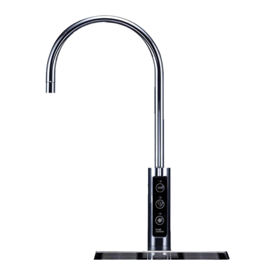
Model Overview Introduction The u1 epitomises cutting-edge design provide ambient still, chilled and/or and innovation with its contoured tap carbonated water. All the materials and and compact under-counter unit. This is components are tested during the entire our most discreet range and will fit into production process in order to satisfy all any environment seamlessly. - Page 3 Component/Feature Overview U1 Tap - Major Components Swan Neck Faucet Main Body Membrane Control Panel Threaded Stem & Back Nut Water Pipe Contents: 1 no Electronic Swan Neck Tap 1 no 2/3-Button Membrane Control Panel 1 no 1.0m x 6mm Insulated Water Pipe...
- Page 4 S2 Electronic - Major Components Faucet Connection Harness Water Inlet Water Outlet CO2 Inlet* Top Panel Power Connection Unit Carry Handle Side Panel Eliwell Control Panel Front Panel Contents: 1 no Undercounter Unit 1 no 2.0m Power Cord Set 1 no 1.0m Faucet Connection Harness 1 no Co2 Regulator with Gauge &...
-
Page 5: Tap Installation
Installation Tap Installation Identify a suitable location for the undercounter unit. It should be positioned within 1.0m of the faucet, and within 2.0m of suitable services connections. Allow enough space to fit the ventilation ducting system. Service Requirements Water: Mains potable water – internally regulated to 1.9bar. Electricity: 13A supply –... - Page 6 400mm Also allow for the height of Allow for the space needed Allow sufficient space for fitting the swan neck under any for forming the required hole. the back nut to the faucet stem. overhanging cupboard/shelf. Relate the selected position to the underneath of the counter and check for any obstructions.
- Page 7 Tap Dimensions 42mm 33.3mm 188mm Borg & Overström Install & Operation Manual...
- Page 8 Driptray Dimensions 12.7mm/ ½” Waste Spigot 150mm/ 180mm/ 5 ² ” 7 ³/ ” 75mm/ 2 ¹ ” 250mm/ 9¹³/ ” 12.7mm/ ½” Waste Spigot 110mm/ 4 ¹¹/ ” 220mm/ 8 ²¹/ ” Borg & Overström Install & Operation Manual...
- Page 9 Ventilation System Installation When Borg & Overström undercounter units performance of the unit. The amount of heat are installed inside a cabinet or generated by the cooling cycle depends housing, adequate ventilation is directly upon the amount of usage – the recommended to ensure that they operate higher the usage, the more heat produced.
- Page 10 Situate the Simple-fit ventilation base in place centrally over the aperture. Ensuring that there is a minimum of 30mm air gap to each side. The S2 appliance must be placed carefully in position on the ventilation base to ensure the chimney is located correctly in the chimney aperture at the rear of the base.
- Page 11 Undercounter Installation & Water Connection Connect the faucet connection Locate the machine in a Connect the u1 tap to the Install within connection box harness to the tap control water outlet. suitable enclosure, ensuring as supplied. panel membrane. that the supplied ventilation kit can be installed.
- Page 12 Water Pipe Tap Control Panel Co2 Pipe* Membrane Faucet Connection Harness Co2 Bottle* Safety The unit should be isolated from the electricity supply before removal of any covers. Great care must be employed when working with high pressure carbon dioxide, and in no cases should the maximum operating pressure of 58 PSI (4 bar) be exceeded.
- Page 13 Sparkling Water Flow Rate - Sparkling Versions Only NOTE: The soda water flow rate is set to 35ml/sec at a CO2 pressure of 58 PSI (4 bar). To adjust the soda water flow rate follow these steps: Loosen the lock nut, but do Locate the flow control adjuster, Remove the 3 screws holding Flow can then be adjusted...
-
Page 14: General Safety
General Safety • Always place the dispenser in its vertical position, on a surface which can capably support its weight. • During use this machine must remain in its upright position. • Adequate ventilation must be allowed for - we recommend using the supplied ventilation ducting kit. -
Page 15: Operation
Operation Functions & Controls Tap Control Panel Ambient Water Indicator Ambient Water Button Sparkling Water Indicator* Sparkling Water Button* Cold Water Indicator Cold Water Button Eliwell Control Panel Digital Display 8888 Control Button Function Button Setting Button Control Button *Sparkling versions only. Borg &... - Page 16 Controls Power Connection Socket Note: the undercounter unit automatically powers up when the power lead is connected. Basic Settings Adjusting the Set Point: 1. Switch on Mains power – the display will 4. Raise or lower this figure to the desired flash several times, then the fridge system setting using the up or down arrows on the will switch on and the display will give a...
- Page 17 CO2 Bottle Installation - Sparkling Versions Only Unpack CO2 Regulator and fit elbow fitting Attach the regulator to the disposable CO2 Connect the assembled CO2 bottle and to spigot outlet. bottle, ensuring the small pressure relief regulator to the CO2 inlet using a ¼” pipe. vent in the stem is facing away from you or anyone else.
-
Page 18: Maintenance And Cleaning
Maintenance & Cleaning Sanitisation Guide NOTE: All maintenance operations must be carried out with the dispenser switched off. This operation must only be carried out by trained staff. Every 6 months a sanitisation procedure is recommended as follows: Turn off incoming mains water. Briefly press cold/ambient dispense Remove the existing filter. - Page 19 mins mins For this we recommend the use Pay particular attention to the Attend to any cosmetic marks of Bioguard Foam Descaler & dispense faucet and the push with Bioguard Rejuvenator & Sanitiser Spray. button controls. For this use Protector as needed. Bioguard External Sanitiser &...
- Page 20 Emptying the CO2 Tank - Sparkling Versions Only Turn off the water supply. Press and hold the Sparkling The tank is empty of sparking water dispense button until all water when only CO2 is being the water is expelled and only released.
Need help?
Do you have a question about the U1 and is the answer not in the manual?
Questions and answers