Table of Contents
Advertisement
Advertisement
Table of Contents

Related Manuals for Tyco MINERVA MZX 125


Summary of Contents for Tyco MINERVA MZX 125
- Page 1 MINERVA MZX 125/250 ADDRESSABLE FIRE DETECTION SYSTEMS USER MANUAL V1.0/13/11/08...
- Page 2 However, should any errors be detected, Thorn Security would greatly appreciate being informed of them. The above not withstanding, Thorn Security can assume no resposibility for any errors in this manual or their consequences. For further information, see Tyco Safety Product’s web site at: www.tycoemea.com...
-
Page 3: Table Of Contents
MZX 125/250 Fire Detection Systems Content Guide to this manual ..........6 Introduction ............6 Key function and features ................6 Operating Instructions........10 Operator’s indicators and controls ............10 3.1.1 General ............................10 3.1.2 Display control module ......................10 3.1.3 Indicators ........................... - Page 4 MZX 125/250 Fire Detection Systems Controller Functions...........25 Access levels ....................25 4.1.1 General ............................25 Entering passcodes ..................26 Valid values ....................26 Main menu....................27 Accept events ....................28 View status ....................28 Isolate/de-isolate ..................31 Time/date ..................... 34 4.8.1 Set time/date ...........................
-
Page 5: Guide To This Manual
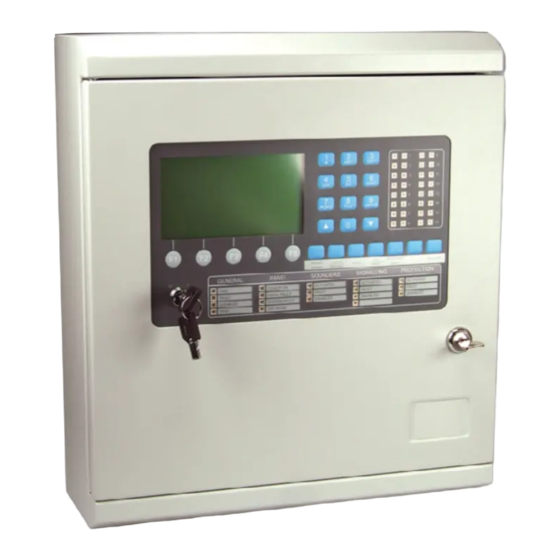
MZX125/250 Manual Guide Guide to this manual In this documentation keywords and symbols denote warnings, info or instructions (see table 1). Keyword Symbol Explanation DANGER Warning. Imminent danger. Death or severe injury when disregarded. WARNING Warning. Potentially dangerous situation. Death or severe injury possible when disregarded. - Page 6 MZX 125/250 Fire Detection Systems Fig.. 1: MZX125 Doc. version 1...
- Page 7 MZX125/250 Fire Detection Systems Fig.. 2: MZX250 Doc. version 1...
-
Page 8: Introduction
MZX250’ fire controllers, any differences being outlined as appropriate This document is written for Firmware Version 14. The MINERVA MZX 125/250, form a comprehensive and compatible range of modular and flexible EN54 approved addressable fire controllers using Tyco MZX Technology... - Page 9 MZX125/250 Fire Detection Systems Constant fault monitoring of all hardware components, power supplies, batteries, relays, sounder and speaker circuits, addressable loops, detectors and addressable devices, monitored input circuits, remote and local communication links. Communication with up to 125 addresses on one detection loop (MZX125) or 250 addresses on one detection loops (MZX250) per controller and a combination of up to 1500 auxiliary I/O, controller plus 7 full function repeaters and multiple remote printers.
-
Page 10: Operating Instructions
MZX 125/250 Fire Detection Systems OPERATING INSTRUCTIONS OPERATOR’S INDICATORS AND CONTROLS 3.1.1 GENERAL ALL operator controls and indicators are mounted on the front panel. 3.1.2 DISPLAY CONTROL MODULE The Display Control Module (Fig. 3 MZX125 and Fig. 4 MZX250) contain the following indicators and controls: A 640 character backlit LCD alphanumeric display, arranged in 16 rows of 40 characters. - Page 11 MZX125/250 Fire Detection Systems Used to enter the number 0 Used to enter the number 1 or special symbols Used to enter the number 2 or letters ‘A’, ‘B’ or ‘C’ Used to enter the number 3 or letters ‘D’, ‘E’...
- Page 12 MZX 125/250 Fire Detection Systems Fig.. 3: MZX125 Display Control Module Doc. version 1...
- Page 13 MZX125/250 Fire Detection Systems PQRS WXYZ SILENCE SILENCE INVESTIGATE RESET EVACUATE RESOUND NIGHT BUZZER DELAY GENERAL PANEL SOUNDERS SIGNALLING PROTECTION FIRE ACTIVATED ACTIVATED ACTIVATED POWER ON MAINS FAULT FAULT FAULT FAULT FAULT DISABLED DISABLED DISABLED DISABLED SYSTEM FAULT TEST DAY MODE ZONE DISPLAY Fig..
-
Page 14: Indicators
MZX 125/250 Fire Detection Systems 3.1.3 CONTROL CONTROL MODULE The Display Control Module contains the following indicators and controls: INDICATORS GENERAL A red Fire LED. A yellow Fault LED. A yellow Disabled LED. A yellow Test LED. PANEL A green Power ON LED. A yellow LED to indicate Mains Fault. -
Page 15: Lcd Display
MZX125/250 Fire Detection Systems ‘DAY MODE’ - used to set the system into the daytime operation mode. ‘INVESTIGATE DELAY’ - is used to end signalling delay time and start the investigation time. ‘SPARE’ - is configurable to customer requirements. ‘EVACUATE’ - is used to activate external sounders. LCD DISPLAY The LCD display is divided into four windows as shown in Fig. -
Page 16: Status Window
MZX 125/250 Fire Detection Systems First Fire Zone 002 B001 1st Floor Corridoor Room 117 Last Fire Zone 030 B055 4th Floor Washroom / Window 3.2.2 STATUS WINDOW The status window displays the number of faults, isolates etc. 3.2.3 MAIN WINDOW The main window displays logs, information text, menus and device identification. -
Page 17: Event Monitoring
MZX125/250 Fire Detection Systems 3.3.1 EVENT MONITORING The term ‘event’ is used to describe a change in system status that must be acknowledged and/or generates an output. Examples of events include: Mains failure Detection of a fire condition Operation of ‘EVACUATE’ key All events trigger a response, the category of which depends on the event type and will be one of the following (in priority order): Full Alarm or Alert... -
Page 18: Operation In Alarm
MZX 125/250 Fire Detection Systems OPERATION IN ALARM 3.4.1 SYSTEM RESPONSE When a fire condition is detected, the system responds as follows: The internal buzzer will sound in a continuous tone. The red ‘FIRE’ LED will light. The SOUNDERS and NOTIFICATION STATUS ‘ACTIVATED’ red LEDs will light. -
Page 19: Sounder Silencing
MZX125/250 Fire Detection Systems The fifth line shows date and time. The sixth line shows the device type. The seventh line shows the actual CURRENT temperature (if heat sensor). The above is only displayed if Extended Alarm Information has been selected at configuration. -
Page 20: Resetting The Controller
MZX 125/250 Fire Detection Systems The system will respond as follows: The sounders will be silenced. The ‘SOUNDER ACTIVATED’ LED will extinguish. All other outputs will remain activated. The LCD display will remain showing the type of alarm and the full zone identification.
Need help?
Do you have a question about the MINERVA MZX 125 and is the answer not in the manual?
Questions and answers