Table of Contents
Advertisement
Quick Links
FIRE FIGHTER'S GUIDE - FFCIF TYPE 3
1.
VIEW NEXT ALARM
Press "NEXT" key once -
-
2.
ACKNOWLEDGE DISPLAYED ALARM
Press "ACK" key once.
-
-
-
3.
RESET ALL ACKNOWLEDGED ALARMS
Press "RESET" key once.
-
-
-
4.
ISOLATE ALL ACKNOWLEDGED ALARMS
Press "ISOLATE" key once.
-
-
-
5.
ISOLATE/DE-ISOLATE BELLS
Press "BELLS ISO" key once.
-
-
-
-
-
-
6.
BRIGADE TEST
Press and hold the "BRIG TEST" key for at least 2 seconds. If enabled:
-
-
The LCD will display the next alarm.
LCD will display "ACKD" for the displayed alarm.
The flashing alarm LED for the zone will go steady.
If all alarms are acknowledged, the ALARM LED will go steady.
LCD will display "Resetting acknowledged alarms".
Alarm LEDs for acknowledged alarms will turn off.
If all alarms are reset, the LCD will display
"No more events in alarm list", otherwise the oldest unacknowledged
alarm will be displayed.
LCD will display "Isolating acknowledged alarms".
Isolate LEDs for acknowledged alarms will turn on.
If all alarms are isolated, the LCD will display "No more events in
alarm list", otherwise the oldest unacknowledged alarm will be
displayed.
If the "Bells Isolate" LED is OFF
The "Bells Isolate" LED will turn ON steady.
The bells will turn OFF if they are ON.
If the "Bells Isolate" LED is ON
The "Bells Isolate" LED will turn OFF.
If any un-isolated alarms exist, the bells will ring.
The FIP will signal Alarm to the brigade.
Any ancillary functions controlled by MAF ALARM will turn ON, unless
they are isolated.
Advertisement
Table of Contents

Related Manuals for Tyco F4000


Summary of Contents for Tyco F4000
- Page 1 FIRE FIGHTER'S GUIDE - FFCIF TYPE 3 VIEW NEXT ALARM Press "NEXT" key once - The LCD will display the next alarm. ACKNOWLEDGE DISPLAYED ALARM Press "ACK" key once. LCD will display "ACKD" for the displayed alarm. The flashing alarm LED for the zone will go steady. If all alarms are acknowledged, the ALARM LED will go steady.
- Page 2 THIS PAGE INTENTIONALLY LEFT BLANK...
- Page 3 Tyco Services Fire & Safety. Information contained in this document is believed to be accurate and reliable, however Tyco Services Fire & Safety reserves the right to change the content without prior notice.
-
Page 4: Installation Details
F4000 LCD Operator's Manual Document No: LT0117 INSTALLATION DETAILS For your reference please complete the following information on the F4000 LCD Fire Indicator Panel supplied. F4000 FIP SUPPLIED BY F4000 FIP INSTALLATION LOCATION CONTRACT/JOB NUMBER F4000 SERIAL NUMBER F4000 SYSTEM AS INSTALLED... -
Page 5: Table Of Contents
Document No: LT0117 F4000 LCD Operator's Manual TABLE OF CONTENTS Installation Details………………………………………………………………………………. ii End User Liability Disclaimer……………………………………………………… Amendments…………………………………………………………………………………….. vi INTRODUCTION ..................1-1 SCOPE........................1-2 ATTACHMENTS ....................1-3 ASSOCIATED DOCUMENTATION ..............1-4 GLOSSARY OF TERMINOLOGY ................. 1-6 SYSTEM DESCRIPTION ................2-1 SYSTEM COMPONENTS.................. - Page 6 F4000 LCD Operator's Manual Document No: LT0117 CONTROL OF FIP BY MULTIPLE OPERATORS ..........4-10 OPERATING INSTRUCTIONS - BRIGADE FUNCTIONS ......5-1 INTRODUCTION TO BRIGADE FUNCTIONS............5-2 SILENCING THE INTERNAL SOUNDER ............. 5-4 ACKNOWLEDGE ZONES IN ALARM ..............5-5 RESET ACKNOWLEDGED ZONES IN ALARM ........... 5-6 ISOLATE ACKNOWLEDGED ZONES IN ALARM..........
- Page 7 Document No: LT0117 F4000 LCD Operator's Manual OPERATING INSTRUCTIONS - ZONE FUNCTIONS........7-1 ZONE ALARM OR FAULT TEST ................7-2 ZONE OR ANCILLARY ISOLATE OR DE-ISOLATE ..........7-6 ANCILLARY TEST ....................7-11 ZONE OR ANCILLARY RESET ................7-13 AUTO-RESET MODE ..................7-15 ZONE STATUS RECALLS..................
-
Page 8: End User Liability Disclaimer
Because this programming facility allows the user to define in detail the operation of the F4000 System which is being customised, changes may be made by the user that prevent this installation from meeting statutory requirements. -
Page 9: Amendments
2.35A 02/05/00 Revised to include networking features from LT0150. 3074 2.37 19/04/01 Brand changed to Tyco. Revised Section 5.2.1 and added 3169 P133A, Z134A details to Appendix A. 2.38 19/04/02 Revised for V2.38 for Dirty Alert, Charger Ignore time after 3288 NZ 1 hour battery test, and Charger LED cadence. - Page 10 F4000 LCD Operator's Manual Document No: LT0117 THIS PAGE IS INTENTIONALLY LEFT BLANK Page viii 19 April 2002 Issue 2.38...
-
Page 11: Introduction
Document No: LT0117 F4000 LCD Operator's Manual Introduction INTRODUCTION Issue 2.38 19 April 2002 Page 1-1... -
Page 12: Scope
Introduction SCOPE The F4000 Fire Alarm System is very powerful and packed with many features. In spite of this, it is very user friendly and intuitive to use. The LCD front panel provides a simple, menu driven interface to allow control of the FIP and, therefore, reference to this manual is rarely required for the experienced fire industry person. -
Page 13: Attachments
A FIRE FIGHTER'S GUIDE is fixed inside the front cover for quick reference in emergencies. If the F4000 FFCIF is configured for Type 2 operation, i.e. global acknowledgement, reset and isolation of zones in alarm, refer to Appendix C for instructions on ensuring that the correct Fire Fighters Guide is used. -
Page 14: Associated Documentation
Volume 1, F4000 Operator's Manual, provides a complete guide to the operation and maintenance of the F4000 FIP and RZDU panels, with Version 1.X software, according to Australian Standards AS1603 Part 4 and New Zealand Standard NZS4512. This manual is provided as standard with non-LCD F4000 FIP panels, and RZDUs (LT0057). - Page 15 Document No: LT0117 F4000 LCD Operator's Manual Introduction 1.3.2 STANDARDS RELATED This manual makes reference to the following Australian Standards: AS1603.4 Automatic Fire Detection and Alarm Systems Part 4 - Control and Indicating Equipment AS1670 Automatic Fire Detection and Alarm Systems- System Design, Installation, and Commissioning.
-
Page 16: Glossary Of Terminology
F4000 LCD Operator's Manual Document No: LT0117 Introduction GLOSSARY OF TERMINOLOGY The following abbreviations and terminology are used in this manual: Analogue Addressable Responder Alternating Current Ancillary Control Zone Advanced Detector Responder unit Addressable Device Unit "ALM" Display abbreviation for ALARM... -
Page 17: System Description
Document No: LT0117 F4000 LCD Operator's Manual System Description SYSTEM DESCRIPTION Issue 2.38 19 April 2002 Page 2-1... -
Page 18: System Components
MASTER display, operator control and Brigade Interface unit of the system. A front panel view of the F4000 LCD FIP is shown in Figure 2.2. This shows a standard panel for up to 48 zones minimum. A 19" RAC cabinet version allows for 64 zones minimum. - Page 19 Document No: LT0117 F4000 LCD Operator's Manual System Description Figure 2.1 F4000 System Block Diagram Issue 2.38 19 April 2002 Page 2-3...
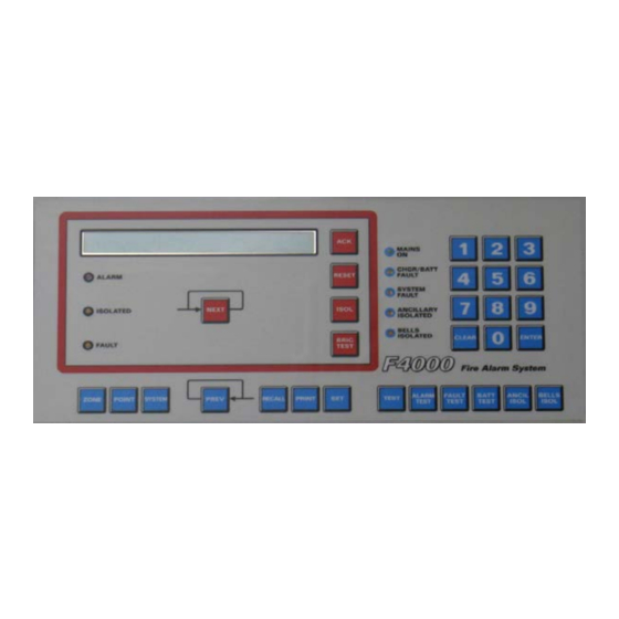
- Page 20 F4000 LCD Operator's Manual Document No: LT0117 System Description Figure 2.2 F4000 LCD Fire Indicator Panel Page 2-4 19 April 2002 Issue 2.38...
- Page 21 Responder, and back to the FIP again. The F4000 System can monitor and control a maximum of 127 Responders. It is this loop system that makes the F4000 System so adaptable since larger systems are implemented simply by extending the loop and adding more Responders in the appropriate places.
- Page 22 ADM133 Input Z54A Heat Base ADC130 Output The device family is programmable on a per MPR basis, and an F4000 system can support "130 Series" MPRs on the same F4000 responder loop. 2.1.4 F4000 COMMUNICATION LOOP The F4000 "COMMUNICATIONS LOOP" is a 4 core loop that runs from the FIP, through each Responder, and back to the FIP again.
- Page 23 The CG4000 will run on an IBM AT or compatible computer. 2.1.7 LOGGING PRINTER A serial printer may be connected to the F4000 Master FIP to provide a log of events and operator actions. The FIP can be programmed to print any combination of the following event types: Zone Events, e.g.
- Page 24 Networked F4000 FIPs allow an operator to send single zone and zone range reset, isolate and de-isolate commands to other FIPs; to recall and search for zone status on other F4000 FIPs; and to alarm, fault, auto reset and operate test zones on other F4000 FIPs.
- Page 25 LCD being essentially the same as a non-networked F4000. A programming terminal operator can connect to another F4000 over the network, and control and view that F4000 via its LCD and keypad as if the operator was at that F4000. 2.1.10 PROTOCOL TRANSLATION MODULE (PTM) The PTM is used with F4000 networks and performs two functions: Interfaces a printer to the network for logging of events from panels on the network.
-
Page 26: Lcd Fip Displays
An LED display card is fitted to show the zone status for each sixteen zones. The minimum number of displays required at an F4000 LCD FIP panel is zero. However, 4 can be fitted in the standard cabinet (FP0746) for displaying up to 64 zones. For New Zealand systems, one of these positions will usually be taken up by the display extender board. - Page 27 Document No: LT0117 F4000 LCD Operator's Manual System Description FIGURE 2.3 F4000 FIP DISPLAY Issue 2.38 19 April 2002 Page 2-11...
-
Page 28: Lcd Keypad Introduction
F4000 LCD Operator's Manual Document No: LT0117 System Description LCD FIP DISPLAYS (CONTINUED) The LED indicators may be either: Unlit (OFF); or Slow Flashing (SF), every 2 seconds; or Flashing (F), every half a second; or Rapid Flashing (RF), 10 times per second; or Steady (ON). - Page 29 F4000 FIP KEYPAD LAYOUT 2.3.1 AVAILABLE FUNCTIONS The F4000 LCD FIP provides all of the isolate and test functions of the original F4000 FIP. However, the new LCD and keypad allow for more features, such as status recalls, history recalls and setting of time and date.
- Page 30 F4000 LCD Operator's Manual Document No: LT0117 System Description AVAILABLE FUNCTIONS (CONTINUED) CRCs/Date Time Database Last Changed Set Commands Time & Date Passwords Most functions are selected by entering a command sequence on the keypad. This manual explains the more basic sequences. Other sequences may exist, which are often the same command sequence with the order of the keypresses altered, or special short cut sequences.
- Page 31 ACZ. The Point number entry prompt has a special entry shortcut. If no point number has been entered when the "Enter" key, or any other valid shortcut key, is pressed the F4000 automatically selects the first configured point, if any.
- Page 32 Point Recall Display - shows either point status (alarm, fault, etc), analogue values (current and tracked values, history), analogue levels (current levels and sensitivities), or detector % dirty information. F4000 V2.35 treats ADR circuits and relays as points, thus their status can be recalled and searched. Page 2-16 19 April 2002 Issue 2.38...
- Page 33 Document No: LT0117 F4000 LCD Operator's Manual System Description LCD INFORMATION DISPLAYS (CONTINUED) The "NEXT" and "PREV" keys display the information for the next or previous point. The selection of the point depends upon the mode of the recall, either all points, or searches for point status meeting certain criteria e.g.
-
Page 34: Audible Tones
F4000 LCD Operator's Manual Document No: LT0117 System Description AUDIBLE TONES Any requirement for operator intervention is signalled by the sounding of the FIP's internal buzzer. The buzzer can be activated in a number of different modes, each of which gives some indication as to the type of event that has occurred. -
Page 35: Networked Panels
NETWORKED PANELS 2.5.1 NETWORK FIP & NETWORK ZONE NUMBERING When F4000 FIPs are networked together there must be a way to identify each FIP and the zones on that FIP. In this manual, reference is made to "local" and "remote" panels. A local panel is the panel at which an operator is controlling the system from. - Page 36 F4000 LCD Operator's Manual Document No: LT0117 System Description 2.5.2 ZONE NUMBER ENTRY EXAMPLES Zone 27 on Local Panel. (ii) Zone 27 on Panel 86. (iii) Zones 5 to 16 on local panel. (iv) Zones 5 to 16 on Panel 7.
- Page 37 (iv) A network F4000 may be programmed to allow control of its bells by other FIPs on the network. Alarms or Trial Evacuation (NZ) on other FIPs may turn the local bells ON.
- Page 38 If the isolates total on the base display is not zero. Flashing: If any point on the local FIP is isolated or a point on a network FIP is isolated and the F4000 is combining MAF status. The FIP buzzer turns on: Steady:...
- Page 39 There may be a noticeable delay at times when a network F4000 attempts to retrieve text and status from another network panel. If there will be a delay, F4000 will display a minimal description on the LCD, eg. Z1057 or Network Panel 75. The actual status will be shown when the true zone name text (if programmed at the remote FIP) is displayed.
- Page 40 Accepted or NOT Accepted response. If network loading is high, or the remote F4000 is busy or is off line, a response may not be received within the programmed time. If the time limit is exceeded, the local F4000 displays the above message. Note that depending on the circumstances, the command may or may not have been received and processed.
- Page 41 The receiver of the exception can then recognise and display the data appropriately. Exceptions have a level of priority assigned to them by the sender. An F4000 can be programmed as to which priorities of exceptions get displayed, and which get ignored.
- Page 42 Consequently, some totals may exceed the maximum totals expected for a single F4000 panel. If there are no off-normals, the "base" display of the F4000 LCD displays the system name, date and time, and F4000 software version. The software version text can be replaced by text that indicates the operational state of the F4000, eg.
- Page 43 2.5.10 NETWORK BELLS CONTROL A V2.3xN F4000 can be configured to allow network bells control. The new functionality is primarily of use by networks in New Zealand, but some features can be used by Australian systems to achieve network-wide bells control.
- Page 44 Pressing the Local Bells Isolate key will cancel any Trial Evacuation and Silence Alarms on the local F4000 that have been activated by a scan failed F4000. It will also cancel the Trial Evacuation state at other FIPs if the Local Bells Isolate state is configured to send a Network Silence Alarms state.
-
Page 45: System Specifications
Document No: LT0117 F4000 LCD Operator's Manual System Specifications SYSTEM SPECIFICATIONS Issue 2.38 19 April 2002 Page 3-1... -
Page 46: System Capacity
F4000 LCD Operator's Manual Document No: LT0117 System Specifications SYSTEM CAPACITY Input Circuits - Up to 508 Circuit Detector Load - 2.5mA for Active EOL (FP0472 ADR) (MAX) - 4.0mA for Active EOL (FP0523 ADR) - 4.0mA for Active EOL (FP0755 ADR-M) - 120µA for Passive 39K EOL... -
Page 47: Physical
Document No: LT0117 F4000 LCD Operator's Manual System Specifications PHYSICAL 3.2.1 FIP, EXTENDERS, RZDUS Standard Cabinets Cabinet Size - 750 mm(H) x 550 mm(W) x 210 mm(D) + 20 mm MCP Cabinet Material - 1.2 mm Mild steel Cabinet Finish... - Page 48 F4000 LCD Operator's Manual Document No: LT0117 System Specifications 3.2.2 RESPONDER UNITS - ADR, AAR, MPR Size - 240 mm(H) x 180 mm(W) x 50 mm(D) Material - 1.0 mm Mild steel Finish - Galvanised Mounting - Surface/Wall mount Access...
- Page 49 Document No: LT0117 F4000 LCD Operator's Manual System Specifications 3.2.5 PROTOCOL TRANSLATION MODULE (PTM) Size 450mm (W) x 280mm (D) x 85mm (H) Material 1.2mm mild steel Finish Cover: Powdercoat Cream Wrinkle BFF-998-CW (Iron Phosphate pretreat) Base: Zinc Plate, Blue Passivate Shipping Weight 3.2.6 PANEL-LINK MODBUS BRIDGE (PMB)
-
Page 50: Electrical
F4000 LCD Operator's Manual Document No: LT0117 System Specifications ELECTRICAL Mains 240 VAC +6% -10%, 50 Hz, 150W Internal Battery 24 VOLT, Sealed lead-acid. Up to 24 Ampere Hour 27.3 VDC (nominal at 20 °C) Regulated Internal Charger (+VB) 27.9 VDC (nominal at 20 °C) (+VNB) -
Page 51: Indicators
Document No: LT0117 F4000 LCD Operator's Manual System Specifications INDICATORS Zone LEDs - Red: ALARM (Optional) - Amber: FAULT, ISOLATE System LEDs - Green: MAINS ON - Red: MASTER ALARM - Amber: SYSTEM FAULT, BELL ISOLATE,SYSTEM TEST, ANCILLARY ISOLATE, CHARGER/ BATTERY FLT. -
Page 52: Keypad Controls
F4000 LCD Operator's Manual Document No: LT0117 System Specifications KEYPAD CONTROLS Keypad Type - 30 key keypad plus 2 line by 40 character LCD Zone Functions - Alarm and Fault Test - Isolate - Reset - Auto-Reset Test Mode - Recalls... -
Page 53: Interpreting The Display
Document No: LT0117 F4000 LCD Operator's Manual Interpreting The Display INTERPRETING THE DISPLAY Issue 2.38 19 April 2002 Page 4-1... -
Page 54: Responding To Alarms
** PLEASE NOTE ** ──────────────────────────────────────────────────────────────────── The above procedure should only be executed by a trained fire officer, and may need to be modified in accordance with any special conditions applying to your F4000 FIP installation. ──────────────────────────────────────────────────────────────────── Page 4-2 19 April 2002... -
Page 55: Dealing With Faults
In normal operation the only lit LED indicator should be the green "MAINS ON". For New Zealand mode F4000 panels the green "NORMAL" LED indicator should also be ON. If other indicators are active, or the "NORMAL" LED is OFF or flashing, this should be reported and promptly investigated. -
Page 56: System Indicators
F4000 LCD Operator's Manual Document No: LT0117 Interpreting The Display SYSTEM INDICATORS NOTE: In the following sections the following abbreviations are used to describe the LED indications: LED unlit. LED flashing slowly (every 2 seconds). LED flashing (every half a second). - Page 57 Document No: LT0117 F4000 LCD Operator's Manual Interpreting The Display 4.3.4 "MAINS ON" LED INDICATOR A Green indicator interpreted as: The normal condition indicating mains power is present An abnormal condition indicating that the mains supply to the FIP has been interrupted.
- Page 58 F4000 LCD Operator's Manual Document No: LT0117 Interpreting The Display 4.3.6 "SYSTEM FAULT" LED INDICATOR An Amber indicator that is interpreted as: The normal condition, indicating that the system is fully operational. Indicates that a system fault (as opposed to a zone fault) has been detected.
- Page 59 4.3.9 "NORMAL" LED INDICATOR (NZ PANELS ONLY) A Green indicator interpreted as: The normal state The F4000 is Normal, but the mains supply is off. An un-isolated alarm or fault condition exists. In this case the appropriate FIRE or DEFECT indicator will be on flashing, An abnormal condition exists, e.g.
-
Page 60: Zone Indicators
F4000 LCD Operator's Manual Document No: LT0117 Interpreting The Display ZONE INDICATORS NOTE: In the following sections the following abbreviations are used to describe the LED indications: LED unlit. LED flashing slowly (every 2 seconds). LED flashing (every half a second). -
Page 61: Led Phasing
Document No: LT0117 F4000 LCD Operator's Manual Interpreting The Display 4.4.3 ZONE ISOLATED ("ISO") LED INDICATOR An Amber indicator per zone that is interpreted as: The normal state; indicates that the zone is not isolated and that any alarm or fault conditions detected on that zone will generate Brigade signals, bell operation, and ancillary device operation as configured for that zone. -
Page 62: Control Of Fip By Multiple Operators
FIG 4.2 PHASING OF DISPLAY BOARDS CONTROL OF FIP BY MULTIPLE OPERATORS For a standalone F4000 FIP, only one operator can have control over the FIP as there is only one operator interface (the keyboard and LCD). When an F4000 FIP is connected to:... -
Page 63: Operating Instructions - Brigade Functions
Document No: LT0117 F4000 LCD Operator's Manual Operating Instructions - Brigade Functions OPERATING INSTRUCTIONS - BRIGADE FUNCTIONS Issue 2.38 19 April 2002 Page 5-1... -
Page 64: Introduction To Brigade Functions
F4000 LCD Operator's Manual Document No: LT0117 Operating Instructions - Brigade Functions INTRODUCTION TO BRIGADE FUNCTIONS 5.1.1 GENERAL OPERATION & DISPLAY When an alarms occurs, the FIP takes over the keypad and LCD to display the alarm. The keys that can be used are limited to those within the Fire Fighters Control and Indicating Facility (FFCIF), the "PREV"... - Page 65 The F4000 FIP maintains a list of alarms in the order in which they occurred. In the absence of operator intervention, the LCD display will show the first alarm. All alarms in the list can be viewed, one by one, by pressing the "NEXT"...
-
Page 66: Silencing The Internal Sounder
F4000 LCD Operator's Manual Document No: LT0117 Operating Instructions - Brigade Functions 5.1.3 FFCIF TYPE 2 OPERATION When the FIP has been programmed for FFCIF Type 2 mode, the LCD displays a message that indicates the global operations that can be performed. Pressing the ACK, RESET or ISOL keys will silence, reset and isolate respectively, all un-isolated zones in alarm (irrespective of their acknowledgement status). -
Page 67: Acknowledge Zones In Alarm
Document No: LT0117 F4000 LCD Operator's Manual Operating Instructions - Brigade Functions ACKNOWLEDGE ZONES IN ALARM 5.3.1 FUNCTION In "FFCIF mode", pressing the "ACK" key performs the following functions: The displayed alarm is acknowledged. The pulsing alarm sounder is silenced. -
Page 68: Reset Acknowledged Zones In Alarm
F4000 LCD Operator's Manual Document No: LT0117 Operating Instructions - Brigade Functions RESET ACKNOWLEDGED ZONES IN ALARM 5.4.1 FUNCTION In "FFCIF mode", pressing the "RESET" key performs the following functions for all zones in the alarm list that have been acknowledged: RESETS all circuits mapped to the acknowledged zone(s). -
Page 69: Isolate Acknowledged Zones In Alarm
Document No: LT0117 F4000 LCD Operator's Manual Operating Instructions - Brigade Functions ISOLATE ACKNOWLEDGED ZONES IN ALARM 5.5.1 FUNCTION In "FFCIF mode", pressing the "ISOLATE" key performs the following functions for all zones in the alarm list that have been acknowledged: ISOLATES all acknowledged zones in the alarm list. -
Page 70: Isolating/De-Isolating Bells
For New Zealand mode F4000 FIPs, the Bells Isolate LED flashes if a Silence Alarms keyswitch has been turned on at the FIP, (2Hz flash), or at any RZDU or Networked FIP (slow flash). -
Page 71: Displaying The Alarm Cause
"POINT" key is pressed the alarm time is displayed along with the full alarm cause information. F4000 V2.31 and later can be programmed to update the alarm cause text whenever a new alarm cause is detected. They can also be programmed to reannunciate a zone alarm when a new cause is received, i.e. -
Page 72: Exiting Ffcif Mode
F4000 LCD Operator's Manual Document No: LT0117 Operating Instructions - Brigade Functions EXITING FFCIF MODE 5.8.1 FUNCTION While in FFCIF mode, access to all other functions and displays is prevented. On occasion it may be necessary to de-isolate a zone or perform some other function. To do so, FFCIF mode must be exited. -
Page 73: Recalling The Alarm List
Document No: LT0117 F4000 LCD Operator's Manual Operating Instructions - Brigade Functions RECALLING THE ALARM LIST 5.9.1 FUNCTION It is possible for there to be un-isolated alarms present in the system, but the display is NOT in FFCIF mode, for example, the operator has exited the FFCIF to perform recall functions. -
Page 74: Brigade Test
If so disabled, pressing the BRIG TEST key will not result in an alarm signal to the brigade, but controlled ancillaries will still operate unless isolated. The Brigade Test function at an F4000 may also be initiated from an RZDU, if it has been programmed to do so. Page 5-12 19 April 2002 Issue 2.38... -
Page 75: Operating Instructions - System Functions
Document No: LT0117 F4000 LCD Operator's Manual Operating Instructions - System Functions OPERATING INSTRUCTIONS - SYSTEM FUNCTIONS Issue 2.38 19 April 2002 Page 6-1... -
Page 76: Battery Test
F4000 LCD Operator's Manual Document No: LT0117 Operating Instructions - System Functions BATTERY TEST 6.1.1 FUNCTION To initiate a test on the standby battery supply by applying a test load for one minute. 6.1.2 OPERATING SEQUENCE (LOCAL PANEL) From any information display or base display press: The LCD displays "Testing battery. - Page 77 An RZDU will signal battery low to the FIP, for a test failure. F4000 V2.31(N) or later FIPs can be programmed for battery disconnect monitoring. If enabled, a battery test is briefly applied every 15 to 63 seconds (depending on the programmed setting) to determine whether the battery is connected, i.e.
-
Page 78: Bell Test
F4000 LCD Operator's Manual Document No: LT0117 Operating Instructions - System Functions BELL TEST 6.2.1 FUNCTION To operate the Bell Output for a period of five (5) seconds. 6.2.2 OPERATING SEQUENCE From any information display or base display press: Note: For a networked panel after pressing SYSTEM a prompt will be given requesting whether the local panel or a remote panel should be tested. -
Page 79: Bell Isolate Or De-Isolate
On New Zealand mode FIPs it is possible to silence the bells via operation of the external Silence Alarms keyswitch on the FIP, an RDU, or another network F4000. This will cause the "BELLS ISOLATED" LED to flash (2Hz or slow), and a fault (defect) to be signalled to the brigade. -
Page 80: Lcd/Lamp (Led) Test
On New Zealand mode FIPs a Lamp Test can also be started by momentarily shorting the LAMP TEST- input on the display extender board input to 0V. F4000 V2.31(N) or later can be programmed to activate the fault or alarm sounder when the system status indicators are being tested. -
Page 81: System Test
Document No: LT0117 F4000 LCD Operator's Manual Operating Instructions - System Functions SYSTEM TEST 6.5.1 FUNCTION The System Test checks the integrity of the system hardware and software. It applies simulated alarm and fault conditions to each circuit to check that the conditions are detected and processed correctly. - Page 82 F4000 LCD Operator's Manual Document No: LT0117 Operating Instructions - System Functions 6.5.3.2 FAULT AND ALARM TEST: The system test then applies "FAULT" and "ALARM" test signals to all enabled responder inputs. The test is deemed complete when all Responders report that their tests have passed.
- Page 83 Document No: LT0117 F4000 LCD Operator's Manual Operating Instructions - System Functions 6.5.5 NOTES System Test is not possible if any unacknowledged alarm or fault exists; or if an automatic test sequence, battery test, zone test or auto-reset zone test is in progress.
-
Page 84: Recall System Faults
F4000 LCD Operator's Manual Document No: LT0117 Operating Instructions - System Functions RECALL SYSTEM FAULTS 6.6.1 FUNCTION Allows an operator to view on the LCD the current causes of a "SYSTEM FAULT" indication. These include problems with the FIP, any Responder or RZDU that could be connected to the FIP, or another panel on a networked system. - Page 85 There is a fault with the FIP LED display chain. ChgrF There is a Charger Fault at the FIP. LpPwr The FIP has detected an F4000 loop power fault. BatLo The FIP has a battery low condition. BatFl The FIP has a battery fail condition.
- Page 86 F4000 LCD Operator's Manual Document No: LT0117 Operating Instructions - System Functions NOTES (CONTINUED) Responders On a per Responder Basis PRly Responder has opened its Power Relay. Scan FIP is not receiving data from this responder. Forgn Responder is unconfigured, or more than one of same address.
- Page 87 Document No: LT0117 F4000 LCD Operator's Manual Operating Instructions - System Functions 6.6.4 NETWORKED PANELS If the local panel detects a network fault (e.g. it fails to receive messages from a remote panel that it is expecting to receive from), or it receives a signal from a remote panel saying that it has a system fault, then NetFlt will be shown.
-
Page 88: System Fault Reset
F4000 LCD Operator's Manual Document No: LT0117 Operating Instructions - System Functions SYSTEM FAULT RESET 6.7.1 FUNCTION To reset, if possible, a latched System Fault as shown by the front panel "SYSTEM FAULT" indicator. The specific cause, or causes, of the "SYSTEM FAULT" indication can be determined by a "RECALL SYSTEM FAULT"... -
Page 89: Recall History
Document No: LT0117 F4000 LCD Operator's Manual Operating Instructions - System Functions RECALL HISTORY 6.8.1 FUNCTION The FIP keeps a list of the last 900 events in chronological order. The RECALL HISTORY command allows an operator to view the historical list of events stored in the FIP, and to move forwards and backwards through the list. - Page 90 There are, however, a number of additional events that can be produced by a networked F4000. Those events relating to a remote panel are identified by a description of SID XX, where XX is the SID of the panel that caused the event.
-
Page 91: Set System Time
"ENTER" key pressed at the start of that minute. F4000 V2.30 onwards can be programmed for automatic daylight saving adjustment of the real-time clock. On a network one panel may be set up as the time/date master. Setting the time or date at this panel will result in the new time/date being sent to other panels on the network. -
Page 92: Set System Date
F4000 LCD Operator's Manual Document No: LT0117 Operating Instructions - System Functions 6.10 SET SYSTEM DATE 6.10.1 FUNCTION Allows an operator to set the date in the real-time clock within the FIP. 6.10.2 OPERATING SEQUENCE To set the date, press: The current date is displayed. -
Page 93: Set Lcd Access Password
Document No: LT0117 F4000 LCD Operator's Manual Operating Instructions - System Functions 6.11 SET LCD ACCESS PASSWORD 6.11.1 FUNCTION Allows an operator to change the LCD Access Password. This password, when entered correctly, allows: Alteration of the password itself. (ii) Alteration of the sensitivity settings of analogue detectors configured in the system. -
Page 94: Global Reset
F4000 LCD Operator's Manual Document No: LT0117 Operating Instructions - System Functions 6.12 GLOBAL RESET 6.12.1 FUNCTION To issue an FFCIF Type 2 Global Reset, to reset all un-isolated zones in alarm (if any) and to signal RESET to the output logic. -
Page 95: Global Isolate
Document No: LT0117 F4000 LCD Operator's Manual Operating Instructions - System Functions 6.13 GLOBAL ISOLATE 6.13.1 FUNCTION To issue an FFCIF type 2 Global Isolate, to isolate all un-isolated zones in alarm (if any) and to signal ISOLATE to the output logic. -
Page 96: Recall System Crcs
F4000 LCD Operator's Manual Document No: LT0117 Operating Instructions - System Functions 6.14 RECALL SYSTEM CRCs 6.14.1 FUNCTION Allows an operator to view on the LCD the Database CRC and the time and date the database was last changed. This information can be used as part of an AS1851.8 testing schedule, and to provide for detection of tampering with the system configuration. -
Page 97: Operating Instructions - Zone Functions
Document No: LT0117 F4000 LCD Operator's Manual Operating Instructions - Zone Functions OPERATING INSTRUCTIONS - ZONE FUNCTIONS Issue 2.38 19 April 2002 Page 7-1... -
Page 98: Zone Alarm Or Fault Test
F4000 LCD Operator's Manual Document No: LT0117 Operating Instructions - Zone Functions ZONE ALARM OR FAULT TEST 7.1.1 FUNCTION To test the circuit inputs of a selected alarm zone and send test alarm signals to the Brigade. Two tests can be performed: A true fault simulation test, or A true alarm simulation test. - Page 99 Document No: LT0117 F4000 LCD Operator's Manual Operating Instructions - Zone Functions 7.1.3 ABORT ZONE TEST Press the "ACK" key at any time to abort the ZONE TEST function. Zone circuits under test are returned to normal. 7.1.4 NOTES An Alarm detected on the zone under test when one is not expected (eg during the FAULT test) is processed normally and the test aborted.
- Page 100 The F4000 will then send the test command to the FIP with the selected zone on it. Page 7-4 19 April 2002 Issue 2.38...
- Page 101 (ii) If an F4000 receives a test command it will process it as if an operator at that FIP had initiated the command. If the LCD at that F4000 is at its base display, then the LCD will indicate that a test is in progress. It will not display the abort prompt that would normally be displayed for a locally initiated test.
-
Page 102: Zone Or Ancillary Isolate Or De-Isolate
F4000 LCD Operator's Manual Document No: LT0117 Operating Instructions - Zone Functions ZONE OR ANCILLARY ISOLATE OR DE-ISOLATE 7.2.1 FUNCTION To isolate or de-isolate a selected zone. Section 7.2.2 covers a single zone at this panel (local), Section 7.2.3 covers a range of local zones, Section 7.2.5 covers a single networked zone and 7.2.6 covers a range of networked zones. - Page 103 Document No: LT0117 F4000 LCD Operator's Manual Operating Instructions - Zone Functions OPERATING SEQUENCE - ZONE RANGE (LOCAL) (CONTINUED) The LCD will display the selected range of zones, i.e. zone n n n to zone m m m inclusive, plus the options to isolate or de-isolate the range.
- Page 104 F4000 LCD Operator's Manual Document No: LT0117 Operating Instructions - Zone Functions 7.2.5 OPERATING SEQUENCE - SINGLE NETWORK ZONE From the base display, press: To isolate or de-isolate network zone n n n n n. Refer to Section 2.5.1 for the format of network zone numbers.
- Page 105 Document No: LT0117 F4000 LCD Operator's Manual Operating Instructions - Zone Functions 7.2.6 OPERATING SEQUENCE - NETWORK ZONE RANGE If a zone recall is being displayed, then press the CLEAR key repeatedly until the LCD is at the base display.
- Page 106 Refer to Section 2.5.6 for more details on these and other possible LCD display messages. Note that if the remote F4000 is unable to de-isolate all of the zones due to some of them having an alarm or fault status, an exception message can be received indicating this. Refer to Section 2.5.7 for a discussion of Exception Messages.
-
Page 107: Ancillary Test
Document No: LT0117 F4000 LCD Operator's Manual Operating Instructions - Zone Functions ANCILLARY TEST 7.3.1 FUNCTION To test the operation of "ACZ 0" or any other Ancillary Control Zone (ACZ), if configured. If the ACZ to be tested is on a remote panel, use the networked zone command (refer Section 7.1.5). - Page 108 F4000 LCD Operator's Manual Document No: LT0117 Operating Instructions - Zone Functions 7.3.4 EXIT TEST Press the "CLEAR" key once, to abort the test before the 30 second timer expires. The ACZ will not be activated. 7.3.5 NOTES An attempt to test an already operated ACZ results in an error beep and no test is initiated.
-
Page 109: Zone Or Ancillary Reset
Document No: LT0117 F4000 LCD Operator's Manual Operating Instructions - Zone Functions ZONE OR ANCILLARY RESET 7.4.1 FUNCTION A Zone Reset command performs the following functions: For Alarm Zones: Resets all circuits mapped to the selected zone. Clears ALARM and FAULT conditions and indications. - Page 110 Refer to Section 2.5.7 for a discussion of Exception Messages. IMPORTANT The range of zones entered at an F4000 must be limited to zones on a single networked FIP, i.e. the range cannot encompass zones on more than one FIP.
-
Page 111: Auto-Reset Mode
The effect of a network zone reset command is dependent upon the type of FIP that receives the command. If a network zone reset command is received by an F4000... If any circuit that is reset remains in alarm or fault, then the zone(s) mapped to by the circuit will also return to alarm or fault. - Page 112 F4000 LCD Operator's Manual Document No: LT0117 Operating Instructions - Zone Functions 7.5.2 OPERATING SEQUENCE From zone recall displays, to Auto-Reset test the displayed zone that is not an ACZ, press: From all other information displays, or the base display, press: to auto-reset test Zone nnn, if Zone nnn is NOT an ACZ.
- Page 113 Auto-Reset mode. This test is similar to the New Zealand FP4 and FP4000 fire alarms non-latching mode, except that with F4000 only the selected zones are in Auto Reset test mode. All other zones function normally.
-
Page 114: Zone Status Recalls
Note that there may be a delay between requesting a network zone status and display of the true status, due to network delays. In this case, F4000 will display default text, ie. just the network zone number, until the data is received. The display will update with the zone name and status when it is received. - Page 115 Document No: LT0117 F4000 LCD Operator's Manual Operating Instructions - Zone Functions 7.6.3 OPERATING SEQUENCE - ZONE SEARCHES The zone search functions allow an operator to query the local FIP and other networked FIPs for zones meeting specified status criteria, e.g. in alarm.
- Page 116 LCD zone that meets the specified criteria. If there are no local zones that meet the criteria, the F4000 then polls the other FIPs on the network to determine whether they have any zones that meet the criteria.
-
Page 117: Operating Instructions - Point Functions
Document No: LT0117 F4000 LCD Operator's Manual Operating Instructions - Point Functions OPERATING INSTRUCTIONS - POINT FUNCTIONS Issue 2.38 19 April 2002 Page 8-1... -
Page 118: Analogue Recalls
F4000 LCD Operator's Manual Document No: LT0117 Operating Instructions - Point Functions ANALOGUE RECALLS 8.1.1 FUNCTION Allows an operator to recall the status or analogue values for a particular point, or, with AAR or MPR support, search for those points meeting a specified criteria, e.g. in dirty alert or in pre-alarm. - Page 119 Document No: LT0117 F4000 LCD Operator's Manual Operating Instructions - Point Functions OPERATING SEQUENCE - ANALOGUE STATUS (CONTINUED) To view the status of other points, press: to view the status of the next configured point. to view the status of the previous configured point.
- Page 120 F4000 LCD Operator's Manual Document No: LT0117 Operating Instructions - Point Functions OPERATING SEQUENCE - ANALOGUE VALUES (CONTINUED) The FIP polls for the current value more often than the other analogue values. Refer to the AAR/MPR Technical Manuals for descriptions of these values.
- Page 121 Document No: LT0117 F4000 LCD Operator's Manual Operating Instructions - Point Functions OPERATING SEQUENCE - SPECIFIC POINT ANALOGUE LEVELS (CONT'D) Note that the temperature reading of the T131A heat detector is only accurate in the range of 50°C to 70°C. At room temperature (eg 25°C) the error in the temperature reading is typically ±10°C.
- Page 122 F4000 LCD Operator's Manual Document No: LT0117 Operating Instructions - Point Functions 8.1.5 OPERATING SEQUENCE - POINT SEARCHES The point search functions allow an operator to query AARs, ADRs and MPRs for points meeting specified status criteria, e.g. in dirty alert. (Note that the AAR must support the search functions.
- Page 123 Document No: LT0117 F4000 LCD Operator's Manual Operating Instructions - Point Functions OPERATING SEQUENCE - POINT SEARCHES (CONT’D) Menu 3: Isolates searches for isolated points. % Dirty searches for dirty detectors. More accesses Menu 1. When the point status search option has been selected, the search begins and the LCD displays "Searching.."...
- Page 124 Dirty display is updated. % Dirty information is displayed only for MPR smoke detector points. For all other points there is no % Dirty level, thus the F4000 displays “No Recall Information Available”. Display Formats The display for point detector dirty levels is:...
- Page 125 Document No: LT0117 F4000 LCD Operator's Manual Operating Instructions - Point Functions OPERATING SEQUENCE - SPECIFIC POINT DETECTOR DIRTY LEVEL (CONT’D) To view the % Dirty levels of other points, press: to view the % Dirty level for the next configured point.
-
Page 126: 8.2 Analogue Detector History, Tracking, Device Reset
F4000 LCD Operator's Manual Document No: LT0117 Operating Instructions - Point Functions 8.2 ANALOGUE DETECTOR HISTORY, TRACKING, DEVICE RESET 8.2.1 FUNCTION Allows an operator to reset the analogue history or tracked value for a detector. These values are stored and maintained at the AAR or MPR. -
Page 127: Setting Detector Sensitivities
Document No: LT0117 F4000 LCD Operator's Manual Operating Instructions - Point Functions 8.2.3 NOTES The analogue history can be used to see fluctuations in a detector's analogue value, and allow adjustment of the sensitivity accordingly. The Tracked Value would normally be reset only if a detector has been replaced. - Page 128 F4000 LCD Operator's Manual Document No: LT0117 Operating Instructions - Point Functions 8.3.2 OPERATING SEQUENCE From the point recall display for the specified point, press: From the base display or any other information display, press: where rrr is the responder number (1-127) ppp is the analogue point number (1-200) The FIP will check to see that the point rrr.ppp is in fact an addressable detector for which...
- Page 129 Document No: LT0117 F4000 LCD Operator's Manual Operating Instructions - Point Functions OPERATING SEQUENCE (CONT’D) Press: to step back one menu level. to step to the next analogue detector. to step to the previous analogue detector. to set the detector sensitivity to the default value.
- Page 130 F4000 LCD Operator's Manual Document No: LT0117 Operating Instructions - Point Functions 8.3.3 NOTES The first time a sensitivity change is attempted, the FIP will determine if access is permitted. This includes testing for the ability to write to the EEPROM (the hardware...
- Page 131 Document No: LT0117 F4000 LCD Operator's Manual Operating Instructions - Point Functions ANALOGUE LEVEL VERSUS SMOKE DENSITY (CONT’D) F4000 FACTORY DEFAULT SENSITIVITY SETTINGS (1) DEFAULT ALTERNATIVE DEVICE PRE- ALARM RATE OF PRE- ALARM ALARM RISE ALARM C7xA 0.35MICX 0.42MICX 0.19MICX 0.27MICX...
-
Page 132: Point Isolation
F4000 LCD Operator's Manual Document No: LT0117 Operating Instructions - Point Functions POINT ISOLATION 8.4.1 FUNCTION Allows an operator to isolate points on an MPR. The isolation status is stored and maintained at the MPR, and is recallable on the FIP display. - Page 133 Document No: LT0117 F4000 LCD Operator's Manual Operating Instructions - Point Functions 8.4.3 NOTES The LCD will immediately display a "Responder type cannot isolate points" message if the point is on a responder NOT configured for point isolation. The LCD will display a "Responder ignored isolate/de-isolate cmd"...
- Page 134 F4000 LCD Operator's Manual Document No: LT0117 Operating Instructions - Point Functions THIS PAGE IS INTENTIONALLY LEFT BLANK Page 8-18 19 April 2002 Issue 2.38...
-
Page 135: Placing Into Operation
Document No: LT0117 F4000 LCD Operator's Manual Placing Into Operation PLACING INTO OPERATION Issue 2.38 19 April 2002 Page 9-1... -
Page 136: General
A module fitted to New Zealand mode FIPs only. This provides the extra NORMAL, FIRE and DEFECT indications, and other output and inputs required for New Zealand mode operation. It mounts in the same manner as a standard F4000 display board. -
Page 137: Mains Isolate Switch
Placing Into Operation MAINS ISOLATE SWITCH To switch the F4000 LCD FIP panel ON or OFF, first open the front protective door and the inner display door. The "MAINS ISOLATE SWITCH" is located at the top left hand side of the cabinet rear, to the left of the mains transformer. -
Page 138: Commissioning Checklist
Placing Into Operation COMMISSIONING CHECKLIST The following commissioning checklist should be copied and completed upon commissioning of the F4000 FIP LCD. It should be placed with other System Configuration Information. 9.4.1 CABINET Cabinet colour - Standard Cream Wrinkle (BFF 998 CW)……………….. - Page 139 Document No: LT0117 F4000 LCD Operator's Manual Placing Into Operation 9.4.2 POWER SUPPLY Number of Power Supplies Fitted (1 to 3).........…....- If more than 1, Configuration Master/Slave/Slave OK......Mains Wired correctly, Cover secured.....……………………….. "Mains Isolate Switch" and "Mains Earth" labels fitted...……………………...
- Page 140 F4000 LCD Operator's Manual Document No: LT0117 Placing Into Operation 9.4.4 DISPLAY(S) / KEYBOARD Total Number of Display Boards : ___________ fitted OK..…………….. Display LEDs aligned OK and all intensities similar ..……………………. Indicators hard against display window ....……………………….. FRC connectors secure ........……………………………..
- Page 141 Document No: LT0117 F4000 LCD Operator's Manual Placing Into Operation 9.4.5 OPERATION Normal Operation - Only "MAINS ON" LED ON ....………………… Plus NORMAL Indicator (NZ Mode Only) System Test OK...........………………………………… Battery Test OK .........………………………………….. Display Test OK .........…………………………………. Bell Test OK ..........……………………………………...
- Page 142 F4000 LCD Operator's Manual Document No: LT0117 Placing Into Operation 9.4.6 INSTALLATION CHECKLIST All detectors listed in Appendix A ......……………………………. Number of detectors per circuit not exceeded ....…………………….. Detectors suitable for environment installed in ..………………………. Detectors and FIP located according to standards ..…………………..
- Page 143 Document No: LT0117 F4000 LCD Operator's Manual Placing Into Operation 9.4.7 FINAL CHECK As Installed Information Drawings Provided ....……………………… As Installed Configuration Parameters provided ..……………………. Installation Info completed on Pg ii of Operator's Manual………………….. Presentation (Interior neat, clean) .....……………………………. Vigilant Rating Label completed ......……………………………...
- Page 144 F4000 LCD Operator's Manual Document No: LT0117 Placing Into Operation 9.4.8 FAULT LIST Page 9-10 19 April 2002 Issue 2.38...
-
Page 145: System Maintenance & Trouble Shooting
Document No: LT0117 F4000 LCD Operator's Manual System Maintenance & Trouble-Shooting SYSTEM MAINTENANCE & TROUBLE SHOOTING Issue 2.38 19 April 2002 Page 10-1... -
Page 146: System Maintenance
10.1 SYSTEM MAINTENANCE The F4000 System is designed for high reliability and minimum maintenance. In Australia, however, in order to comply with the requirements of AS1851.8, the owner/occupier (or a nominated representative) must carry out system tests on a regular basis. - Page 147 The service/maintenance company should ensure that the performance of the procedure set out in AS1851.8 is witnessed by the owner of the F4000 System installation, or their authorised agent. Issue 2.38...
- Page 148 If the F4000 System develops a fault condition which cannot be solved by following Basic Trouble-Shooting, please call your maintenance company. It is strongly advised that "ON SITE" repair of the F4000 boards or responder units should not be done.
-
Page 149: Trouble-Shooting
Document No: LT0117 F4000 LCD Operator's Manual System Maintenance & Trouble-Shooting 10.2 TROUBLE-SHOOTING 10.2.1 PRELIMINARY INVESTIGATIONS To prevent unnecessary service calls, or in the event of a genuine call, to save time and provide the service company with accurate data the owner/occupier can carry out the... - Page 150 F4000 LCD Operator's Manual Document No: LT0117 System Maintenance & Trouble-Shooting TABLE 10.1 Trouble-Shooting CONDITION REASON ACTION "MAINS ON" LED OFF MAINS SWITCH OFF Turn Mains Switch ON REPORTED POWER Check that LED turns ON BLACKOUT when power is restored...
- Page 151 Document No: LT0117 F4000 LCD Operator's Manual System Maintenance & Trouble-Shooting 10.2.2 PREVENTION OF FALSE ALARMS All fire detection systems rely on their ability to identify atmospheric or environmental changes brought about by the presence of fire. They employ various types of sensors to monitor specific conditions.
- Page 152 F4000 LCD Operator's Manual Document No: LT0117 System Maintenance & Trouble-Shooting THIS PAGE IS INTENTIONALLY LEFT BLANK Page 10-8 19 April 2002 Issue 2.38...
- Page 153 ADU006 Z54A The actual maximum number of devices and types per line/loop depends on the mixture of types, cable type and cable length. Refer to the F4000 Product Manual Volume 9-2, MPR Engineering Manual for further information. A.1.2 MPR IN 130 SERIES MODE Device Type Max.
- Page 154 Actuating Device Compatibility A.3 ADR ACTUATING DEVICE COMPATIBILITY The following detectors, as well as hard contact devices, are compatible with the F4000 System ADVANCED DETECTOR RESPONDER. The maximum number of detectors per circuit is indicated by the columns for the 4mA ADR (FP0523 and FP0755 ADR-M), and 2.5mA ADR (FP0472), with the end of line device keys being represented by P for Pulsing...
- Page 155 Document No: LT0117 F4000 LCD Operator's Manual Actuating Device Compatibility DETECTORS CERTIFIED WITH F4000 FIP MAX NO. (SSL # 131) TYPE DESCRIPTION 2.5mA 4/2.5 B111B BEAM TYPE SMOKE DETECTOR (SEE NOTE 7) B21B BEAM TYPE SMOKE DETECTOR C23B *& IONISATION SMOKE DETECTOR...
- Page 156 F4000 LCD Operator's Manual Document No: LT0117 Actuating Device Compatibility DETECTORS CERTIFIED WITH F4000 FIP MAX NO. (SSL # 131) TYPE DESCRIPTION 2.5mA 4/2.5mA DCA-B-60R HEAT DETECTOR TYPE A DCA-B-90R HEAT DETECTOR TYPE C DCC-A HEAT DETECTOR TYPE A DCC-C...
- Page 157 Document No: LT0117 F4000 LCD Operator's Manual Actuating Device Compatibility ──────────────────────────────────────────────────────────────────── ADR ACTUATING DEVICE COMPATIBILITY - NOTES ──────────────────────────────────────────────────────────────────── 1) The maximum number of detectors per AZF/AZC allowed by the standard is 40. 2) Detectors shown in brackets have the same characteristics as the current models.
- Page 158 F4000 LCD Operator's Manual Document No: LT0117 Actuating Device Compatibility THIS PAGE INTENTIONALLY LEFT BLANK Page A-6 19 April 2002 Issue 2.38...
- Page 159 Document No: LT0117 F4000 LCD Operator's Manual Compatible Batteries APPENDIX B COMPATIBLE BATTERIES The following series of batteries are compatible with the F4000 FIP: Sonnenschien A200 series Up to 20 AH Sonnenschien A300 series Up to 24 AH Power-Sonic PS12 series...
- Page 160 F4000 LCD Operator's Manual Document No: LT0117 Compatible Batteries THIS PAGE INTENTIONALLY LEFT BLANK Page B-2 19 April 2002 Issue 2.38...
- Page 161 APPENDIX C FFCIF TYPE 2 FIRE FIGHTERS GUIDE The F4000 LCD FIP is configurable for Type 2 operation i.e. global acknowledgement, reset and isolation of zones in alarm. If the FFCIF is configured to be Type 2, the standard FFCIF Type 3 Fire Fighters Guide must be amended to add instructions for the enhanced operation.
- Page 162 F4000 LCD Operator's Manual Document No: LT0117 FFCIF Type 2 Fire Fighters Guide FIRE FIGHTERS GUIDE - FFCIF TYPE 2 ACKNOWLEDGING ALARMS Press "ACK" key once. The local sounder will silence but the alarm bells will continue to ring. Press Bells Isolate, if required, to stop the bells ringing.
Need help?
Do you have a question about the F4000 and is the answer not in the manual?
Questions and answers