Table of Contents
Advertisement
Quick Links
HAND-FOOT CONTAMINATION
MONITORS
HF-50, HF-100, HF-150, HF-300, HF-350
HF-4A, HF-4B, HF-4C, HF-4D, HF-4E
Type: K1010, K1011, K1012, K1013, K1014,
K1175, K1176, K1177, K1178, K1179
Instructions for Use
VF, a.s.
Svitavská 588
CZ 679 21 Černá Hora
tel. +420 516 428 611
fax +420 516 428 610
info@vfnuclear.com
www.vfnuclear.com
VF1807090083 EN
revision
version 07
2019
Advertisement
Table of Contents

Related Manuals for VF HF-50

Summary of Contents for VF HF-50
- Page 1 HAND-FOOT CONTAMINATION MONITORS HF-50, HF-100, HF-150, HF-300, HF-350 HF-4A, HF-4B, HF-4C, HF-4D, HF-4E Type: K1010, K1011, K1012, K1013, K1014, K1175, K1176, K1177, K1178, K1179 Instructions for Use VF, a.s. VF1807090083 EN Svitavská 588 CZ 679 21 Černá Hora revision tel. +420 516 428 611...
- Page 3 2.Occupational safety, fire protection and environmental impacts ....14 2.1. Occupational safety 2.1.1 Safety signs used in VF, a.s. and their meanings ..............14 2.1.2 Obligations of the operator ....................14 2.1.3 Qualification requirements of the staff ................15 2.1.4 Conditions for the safe operation of electrical equipment ............. 15 2.2.
-
Page 4: Table Of Contents
6.5.8 Detectors response ......................53 6.5.9 Reset ..........................54 7.Instrument settings ..................55 7.1. Setting the measurement parameters by means of the VF-Setup service software 7.2. Setting the measurement parameters by means of web interface 7.2.1 Instrument settings ......................58 7.2.2 Detectors settings ...................... - Page 5 Table of Contents 8.7. Metrological traceability 8.8. Photomultiplier (PMT) life 9.Troubleshooting ....................69 9.1. High background level 9.2. Possible detector contamination 9.3. Communication failure 10.Delivery parts....................74 10.1. Standard delivery parts 10.2. Accessories, additional equipment and related products delivered separately 10.3.
- Page 6 Fig. 40 Display – Network connection setup ....................52 Fig. 41 Display – Detectors status ........................52 Fig. 42 Detector response ..........................54 Fig. 43 VF-Setup: Setting the communication ....................55 Fig. 44 Web interface login form ........................56 Fig. 45 Web interface - menu .......................... 57 Fig.
- Page 7 List of Figures Fig. 47 Web interface – Device parameters (page 2) ..................58 Fig. 48 Web interface – Detectors settings ...................... 60 Fig. 49 Foil in a cardboard frame measurement for alpha radiation ............... 63 Fig. 50 Optional accessories - foot detector protective foil or frame with a protective foil ......63 Fig.
- Page 8 List of Tables List of Tables Tab. 1 EU guidelines and Government Orders ....................13 Tab. 2 Technical standards ..........................13 Tab. 3 Overview of monitor types ........................26 Tab. 4 Terminal connectors ..........................30 Tab. 5 Description of the terminal board XC1 ....................33 Tab.
- Page 9 Read carefully the Instructions for Use before using the HF Hand-Foot Contamination Monitor and follow its suggestions. The information contained in these Instructions for Use is the exclusive property of VF, a.s., and may not be modified, copied or disclosed to third parties without the company's knowledge.
- Page 10 Introduction Introduction 1.1. Instrument specifications The HF series hand-foot contamination monitors are intended to measure surface contamination by alpha, beta and gamma emitting radionuclides on hands, feet, and clothing. Typical usage is at nuclear power plants, radio-chemical plants, research institutes, hospitals, etc. 1.2.
- Page 11 Introduction 1.3. Terms and definitions Activity A quotient of the mean number of spontaneous nuclear transitions from an energy state in an amount of radionuclide in a time interval. The unit is [Bq]. Alarm level Value (threshold) that is preset inside the instrument. If this value is exceeded, the alarm will be activated.
- Page 12 Introduction Pulse count The total number of counts per preset time interval. Reference background Background that simulates the ambient background for which the instrument is specified. The decision making level and the detection limit are usually determined for a typical value of the reference background of 100 nGy/h, unless stated differently.
-
Page 13: Tab. 1 Eu Guidelines And Government Orders
Introduction 1.4. Acts, regulations and standards The acts, regulations and standards provided herein are valid in the European Union. The instrument meets and follows the directives and government regulations referred to in Tab. 1 as well as the harmonized technical standards referred to in Tab. - Page 14 A summary of measures laid down by legislation and recommended by the producer that should prevent risk or detriment to human health in work. 2.1.1 Safety signs used in VF, a.s. and their meanings Attention, electrical equipment. Do not dispose of with regular The appliance is supplied by AC voltage waste.
- Page 15 Occupational safety, fire protection and environmental impacts 2.1.3 Qualification requirements of the staff The instrument may only be installed by a person familiar with the operational, safety and any other regulations relating to work safety, in force in the place of location of the instrument or otherwise associated with the place of work.
- Page 16 When disposing of the instrument after the expiration of its life, you must follow applicable local legislation VF, a.s. is involved in the RETELA collective take-back system for the manufacturers of electrical instruments. For more information on the RETELA system, please visit http://www.retela.cz/ as well as http://www.weee-forum.org/.
- Page 17 Technical specification Technical specification Hand-Foot Contamination Monitor HF-50 HF-100 HF-150 HF-300 HF-350 (4 vertical hand detectors) Type K1010 K1011 K1012 K1013 K1014 Hand-Foot Contamination Monitor HF-50 HF-100 HF-150 HF-300 HF-350 (2 horizontal hand detectors) Type K1175 K1176 K1177 K1178 K1179 Only figures with tolerances or limits are guaranteed data;...
- Page 18 Technical specification Environmental conditions Range of working temperatures (0 ÷ +40) °C (32 ÷ +104 °F) Working relative humidity max. 90 %, non-condensing Working pressure (86 ÷ 106) kPa Storage conditions Range of storage temperatures (-25 ÷ +40) °C (-13 ÷ +104 °F) Storage relative humidity max.
- Page 19 Technical specification Radiometric parameters Parameter Detector Measurement range Detector background SCD-286A 4 cps to 100 kcps < 0.1 cps, typically 0.04 cps SCD-286B 6 cps to 100 kcps < 20 cps, typically 10 cps SCD-286C (alpha) 4 cps to 100 kcps <...
- Page 20 Technical specification 3.2. Surface Contamination Detector SCD-525 Detectors specification SCD-525A: Alpha in one channel SCD-525B: Alpha + Beta in one channel Detected radiation SCD-525C: Alpha / Beta in two channels SCD-525D: Alpha + Beta + Gamma in one channel SCD-525E: Alpha / Beta+Gamma in two channels SCD-525A: ZnS(Ag) on acrylic glass, 1.5 mm thickness.
- Page 21 Technical specification Radiometric parameters Parameter Detector Measurement range Detector background SCD-525A 4 cps to 100 kcps < 0.25 cps, typically 0.12 cps SCD-525B 6 cps to 100 kcps < 40 cps, typically 20 cps SCD-525C (alpha) 4 cps to 100 kcps <...
- Page 22 Technical specification 3.3. Smart Frisking Probe SFP-100 Detectors specification SFP-100A: Alpha in one channel SFP-100B: Alpha + Beta in one channel Detected radiation SFP-100C: Alpha / Beta in two channels SFP-100D: Alpha + Beta + Gamma in one channel SFP-100E: Alpha / Beta+Gamma in two channels SFP-100A: ZnS(Ag) on acrylic glass, 1.5 mm thickness.
- Page 23 Technical specification Radiometric parameters Parameter Detector Measurement range Detector background SFP-100A 4 cps to 100 kcps < 0.1 cps, typically 0.05 cps SFP-100B 6 cps to 100 kcps < 10 cps, typically 5 cps SFP-100C (alpha) 4 cps to 100 kcps <...
- Page 24 Foot detectors Frisking probe Nuclide (SCD-286) (SCD-525) (SFP-100) Channel beta alpha beta alpha beta alpha beta alpha HF-50 Am-241 120 Bq 240 Bq 200 Bq HF-100 Cl-36 120 Bq 240 Bq 200 Bq HF-150 Cl-36 Am-241 120 Bq 24 Bq...
-
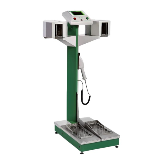
Page 25: Fig. 1 Hand-Foot Contamination Monitor
General description General description 4.1. Purpose of the instrument The HF series Hand-Foot Contamination Monitors are intended for the measurement of surface contamination by alpha, beta and gamma emitting radionuclides on hands, feet, and clothing (when equipped with optional frisking probe). The monitor can be used in nuclear power plants, radio-chemical plants, research institutes with reactors, PET centres, etc. -
Page 26: Tab. 3 Overview Of Monitor Types
(with alpha radiation discrimination). Trade No. of Type Channel A Channel B Version of hand detectors name channels K1010 HF-50 alpha K1011 HF-100 alpha+beta K1012 HF-150 beta alpha vertical... -
Page 27: Fig. 2 Structural Lay-Out
General description 4.3. Design overview display Lock Acoustic signalization Hand detectors Visual signalisation Frisker Adjustable legs Base with foot detectors Foot detectors with cover grid Fig. 2 Structural lay-out Earth leakage breaker Version with main switch Version with main switch at inside of instrument base back side of instrument base Screw... -
Page 28: Fig. 4 Upper Box With Electronics
General description Voice module A fan for cooling of PLC and electronics Router of detectors Fig. 4 Upper box with electronics Memory card Volume setting of Volume "audible setting of messages“ "beeps“ Fig. 5 Voice module Version with ID card reader Card reader (various types) revision... -
Page 29: Fig. 6 Dimensions Of The Variant With Vertical Layout Of Hand Detectors
General description Fig. 6 Dimensions of the variant with vertical layout of hand detectors revision VF1807090083 EN... -
Page 30: Fig. 7 Terminal Connectors On The Rear Side Of The Box With The Plc
General description 4.3.1 Connectors, description and location A summary of instrument connectors is given in Tab. 4. The USB Service connector serves for connecting a service PC. The I/O connector serves for connecting to technology using five relay outputs and two digital inputs. - Page 31 Before putting the instrument into operation Before putting the instrument into operation Avoid the contact of sharp objects with the sensitive area of the detectors. The aluminized light-tight foil can be damaged through the protective grid of the detectors, with possible damage to the photomultiplier. 5.1.
-
Page 32: Storage
Before putting the instrument into operation 5.4. Storage Store the instrument in a vertical position. Store the instrument in suitable environment. The instrument should not be stored without switching on for more than 3 months. Store the instrument in conditions that eliminate any mechanical damages. Avoid contact with water, chemicals and/or rain. -
Page 33: Tab. 5 Description Of The Terminal Board Xc1
Before putting the instrument into operation fit a socket to the ends of the conductors, connect the conductors to the terminal board XC1 (by inserting), see Tab. 5, fix the cable in the grommet, connect the supply cable into AC mains. ... -
Page 34: Operation Verification
Before putting the instrument into operation Hexagonal screws M3 Breaker Fig. 10 Removal of the cover at the back part of the base and actuation of the FZ1 breaker Use adjustable legs, placed in the corners of the instrument base, to adjust the position of the instrument in the place of installation. -
Page 35: Version With An Identification Card Reader
Before putting the instrument into operation Fig. 12 Display – Basic screen 5.6.2 Version with an identification card reader The procedure corresponds to that for the version without a reader. When moving to the measurement position, the instrument will prompt you to use an identification card. Fig. -
Page 36: Calibration Of The Plc Screen
Before putting the instrument into operation 5.6.5 Calibration of the PLC screen It is advisable to calibrate the screen during installation of the instrument. The screen should be calibrated when the display fails to respond correctly to the pressingof functional buttons. Screen calibration can be a part of the periodic maintenance of the instrument, see Chapter 8. -
Page 37: Instructions For Use
Instructions for use Instructions for use If the instrument is turned off, turn it on according to Chapter 5.6.1. 6.1. Visual and acoustic signalization Various phases of measurement, operating instructions and measurement evaluation are communicated visually to the user by means of the PLC display and two indicator lamps as well as acoustically by means of voice messages. -
Page 38: Control Elements
Instructions for use 6.2. Control elements The instrument is controlled by means of the PLC touch-screen display and using the position sensors of the hand and foot detectors and the frisker sensor 6.3. Basic screen After switching on the instrument, the display will go to the basic screen in which the instrument is ready for measurement. -
Page 39: Contamination Measurement Procedure
Instructions for use 6.4. Contamination measurement procedure Avoid contact of sharp objects with the sensitive area of the detectors. The aluminized light- tight foil can be damaged through the protective grid of the detectors, with the subsequent possible damage to the photomultiplier. With standard operation, the monitor is permanently measuring and evaluating the background level in the meantime between measurements of individuals. -
Page 40: Fig. 19 Display - Measurement In Progress
Instructions for use After the correct position is taken, the measurement starts automatically (Fig. 19). Fig. 19 Display – Measurement in progress If no contamination is detected (Fig. 20 and Fig. 21), leave the instrument. Fig. 20 No contamination detected Fig. -
Page 41: Fig. 23 Display - Measurement Not Completed
Instructions for use If you leave the instrument while assuming the position or during measurement, the measurement process will be interrupted (Fig. 23). Fig. 23 Display – measurement not completed Depending on the setting in the configuration file, the monitor contamination test can take place after the interruption of the measurement (Fig. -
Page 42: Contamination Detection By Frisker
Instructions for use 6.4.1 Contamination detection by frisker The Smart Frisking Probe (Fig. 25) is an optional accessory. If it is connected to the instrument, it enables the detection of any possible contamination, mainly on other parts of the body or on clothing and working equipment. -
Page 43: Display Of Measurement Results
Instructions for use After finishing your measurement, hook up the frisker back on the supporting pillar of the instrument, terminating automatically the frisker measurement mode. 6.4.2 Display of measurement results Enter the display of measurement results mode from the basic screen (see Chapter 6.3). ... -
Page 44: Service Menu
(Chapter 6.5.9). Open the service menu by pressing the VF logo (Fig. 30). The menu items are shown in Fig. 32. If the service menu is displayed, the instrument does not measure contamination. Press to enter the service menu Fig. -
Page 45: Fig. 31 Display - Access To The Service Menu
Instructions for use Enter the password for access to the service menu. Fig. 31 Display – Access to the Service menu Press to return Fig. 32 Display – Service menu options Press the red arrow in the upper part of the screen to return to the basic screen (see Fig. 32). A document containing access passwords set by the manufacturer is a part of the shipment (see Chapter 10.1). -
Page 46: Export Archive, Export Errors
Instructions for use Chapter 6.5.1 Chapter Chapter 6.5.4 6.5.2 Chapter Chapter 6.5.3 6.5.1 Chapter 6.5.2 Chapter 6.5.8 Chapter 6.5.7 Chapter 6.5.5 Chapter Chapter 6.5.6 6.5.9 Fig. 33 Display - Service menu 6.5.1 Export archive, Export errors You can export the results of individual contamination measurements, which are recorded in the measurement archive on the PLC storage disk, to a USB flash drive using the Export archive option. -
Page 47: Fig. 34 Display - Export Archive In Progress
Instructions for use Fig. 34 Display – Export archive in progress First row of Second row of Meaning Meaning the heading the heading Record identification number Date format: YYYY = year Date Record date YYYY-MM-DD MM = month DD = day Time format: HH = hour Time... -
Page 48: Clear Archive, Clear Archive Of Error
Instructions for use Value Description Measurement of contamination of hands and feet Measurement using the frisker Not contaminated Contaminated Not decided 3 - 7 always 0 Tab. 9 The meanings of bits of the contamination measurement bit mask Value Description Disabled detector Enabled detector Not contaminated... -
Page 49: Configuration Export
Instructions for use Press to return Press to purge archive Fig. 35 Display – Clear archive Press to return Press to purge error archive Fig. 36 Display - Clear error archive 6.5.3 Configuration export You can export a copy of the configuration file "config.xml", which is stored on the PLC storage drive, to the USB flash drive using the Configuration export option. -
Page 50: Configuration Import
Instructions for use Connect the USB flash drive to the instrument using the USB connector (see Chapter 4.3.1). Press the Configuration export option in the service menu. The configuration file export screen appears on the display (Fig. 37). ... -
Page 51: Date And Time
Instructions for use Press to return Press to start configuration import Fig. 38 Display – Configuration import 6.5.5 Date and time You can set the date and time using the Date and time option. Press the option Date and time in the service menu. The display shows the screen to set the date and time (Fig. -
Page 52: Ethernet Setup
Instructions for use 6.5.6 Ethernet setup You can set your network connection using the Ethernet setup option. Press the Ethernet setup option in the service menu. The display shows the screen to set the Network connection (Fig. 40). The numeric keypad through which you can set an appropriate value is displayed by pressing the white fields. -
Page 53: Detectors Response
Instructions for use Second row First row of of the Value meaning the heading heading Current counts sent in the respective measuring channel in one sampling period. Sampling period is set to 1 s for hand and foot detectors and to 200 ms for the frisker. -
Page 54: Reset
Instructions for use Set measuring time Start – Stop measurement Fig. 42 Detector response 6.5.9 Reset Press the button to software-reset the PLC (without further confirmation). The program will go through the instrument initialization, the test of all peripherals to the background measurement and subsequently to the basic screen “Ready for measurement”. -
Page 55: Instrument Settings
Open the communication port and proceed as per the document VF S0506-25-BN01. Fig. 43 VF-Setup: Setting the communication The VF-Setup service software in the configuration for service partners can be delivered only to the service organizations trained by the manufacturer or to the user's employees trained by the manufacturer. -
Page 56: Setting The Measurement Parameters By Means Of Web Interface
Instrument settings 7.2. Setting the measurement parameters by means of web interface The selected measurement parameters can be set by means of web interface. The changed parameters will be automatically saved in the “config.xml” configuration file. This may be backed up on external storage medium, as required (see Chapter 6.5.3). -
Page 57: Fig. 45 Web Interface - Menu
Instrument settings Preview – authorisation to preview parameters without the possibility to modify them The main menu will appear when the login is successful (Fig. 45). Fig. 45 Web interface - menu The meanings of the menu items Device settings –... -
Page 58: Instrument Settings
Instrument settings 7.2.1 Instrument settings The screens with adjustable parameters for the whole instrument are shown in Fig. 46 and Fig. 47 (switchable pages 1 and 2). Parameters saved in the instrument are reloaded when the Refresh option is selected. ... -
Page 59: Tab. 12 Web Interface - Device Parameters
Instrument settings Identification (Abbreviation) Description Minimum contamination Minimum permitted measurement time, when the instrument, with the TMmin measurement time specified measurement conditions, can decide and display the result Maximum contamination Maximum permitted measurement time, when the instrument with the TMmax measurement time specified measurement conditions, must decide and display the result It indicates the length of buffer for background measurement and the... -
Page 60: Detectors Settings
Instrument settings 7.2.2 Detectors settings The adjustable measurement parameters for individual detectors (or detector channels) are shown in Fig. 48. Select the detector to be set in the left bottom menu: BLH - Back of left hand PLH - Palm of left hand BRH - Back of right hand PRH - Palm of right hand LF –... -
Page 61: Tab. 13 Web Interface - Detectors Settings
Instrument settings Identification (Abbreviation) Description The parameter logically enables (activates) or disables (deactivates) the selected detector. It can be used in cases of failure of any of the detectors to be able to operate the instrument without such failed detector. Be careful Detector logically enabled with the parameter nDoff, which determines the minimum number of enabled detectors. -
Page 62: Maintenance And Care Of The Instrument
Maintenance and care of the instrument Maintenance and care of the instrument When performing maintenance and care of the instrument, follow the requirements and principles of work safety, Chapter 2.1. 8.1. Daily maintenance Inspect the instrument visually. Where necessary, clean the protective foils of the foot detectors (see Chapter 8.4). ... -
Page 63: Protective Foils Of Foot Detectors
Maintenance and care of the instrument 8.4. Protective foils of foot detectors Protective foils for the foot detectors (Fig. 50) can be supplied as optional accessories. The foil serves as an additional mechanical protection of detectors. Foils are inserted inside the base between the detectors and the hinged protective grids;... -
Page 64: Cleaning The Dirt Tray For Hand Detectors
Maintenance and care of the instrument Detector Fig. 51 Orientation of protective foil on a paper reel Fig. 52 Protective foil in a frame on the foot detector (with open protective grid) 8.5. Cleaning the dirt tray for hand detectors 1. -
Page 65: Fig. 53 Cleaning The Dirt Tray For Hand Detectors
Maintenance and care of the instrument Disassembled triangular grid Pull-out metal dirt tray Position of the M4 allen screw which enables removing the triangular grid Fig. 53 Cleaning the dirt tray for hand detectors revision VF1807090083 EN... -
Page 66: Checking The Switches For Foot Detector Grates
Maintenance and care of the instrument 8.6. Checking the switches for foot detector grates Use the wrench (M13) to loosen the nut in the middle of the pillar of the instrument and lift up the grids above the detectors. If used, remove the rolls or frames with the protective foil. Clean the interior around the detectors. -
Page 67: Metrological Traceability
Maintenance and care of the instrument 8.7. Metrological traceability The instrument has been calibrated pursuant to IEC 61098 Radiation Protection Instrumentation - Installed personnel surface contamination monitoring assemblies. The primary adjustment and calibration are carried out by the manufacturer. ... -
Page 68: Photomultiplier (Pmt) Life
The time dependence is a routine matter, i.e. the photomultipliers should be sorted for selected applications. Each PMT is in VF tested and assessed as to whether or not its parameters meet the expected requirements. The PMT testing and stabilization take usually 48 hours. The chart shows the typical dependence of anode current over time. -
Page 69: Troubleshooting
Troubleshooting Troubleshooting The state when the instrument is not able to measure is indicated by a glowing red lamp and a failure report is shown on the display. Format of failure reports: <failure number> Out of order E <Failure report text> Fig. -
Page 70: Tab. 14 Failure Reports
Troubleshooting Failure report What to do? Reset or switch the instrument off and on <detector> Error during calculation If the error is not removed by restarting, contact the authorized <channel name> service organization Reset or switch the instrument off and on <detector>... -
Page 71: High Background Level
Troubleshooting 9.1. High background level Fig. 58 Display – High background level When measuring the background, the monitor continuously evaluates whether it is able to detect the required surface activity corresponding to the surface activity alarm level (contamination signalling). If the background response exceeds the limit where it is no longer able to detect the respective surface activity (not able to signal the set surface activity alarm), the monitor is not able to measure. -
Page 72: Possible Detector Contamination
Troubleshooting 9.2. Possible detector contamination Detector contamination is indicated if the permitted background limit is exceeded when the previous measurement ended with a contamination finding. The state is signalled by a symbol at the given detector. In such a case, the detector must be decontaminated or replaced (the light-tight foil could be damaged). The instrument will be put into an "Out of service"... -
Page 73: Communication Failure
Troubleshooting 9.3. Communication failure "Out of service" and "Device addr. xxx no communication" will appear on the display in the case a of loss of communication with any detector or instrument component. In case of detector failure, the state is represented by a symbol at the given detector (Fig. -
Page 74: Delivery Parts
10.1. Standard delivery parts Item specification Identification (VF stock number) Quantity Hand-Foot Contamination Monitor According to order 1 pc Service SW, VF-Setup (except HF-50) 53-A-0000006 1 pc Tab. 16 Standard delivery parts 10.2. Accessories, additional equipment and related products delivered separately Item specification... -
Page 75: Warranty Conditions
Warranty conditions Warranty conditions The warranty applies to all faults caused by material defects or by instrument malfunction. The warranty is subject to adherence to the Instructions for Use and to the performance of maintenance and care of the instrument without making any changes to the structure of the instrument. Within the warranty period, the manufacturer guarantees free-of-charge repair under the following conditions: ... - Page 76 The instrument is delivered by and the warranty and after- Contact the service partner: warranty service is provided by: Czech Republic: VF, a.s., Svitavská 588, 679 21 Černá Hora Phone: +420 516 42 86 11, Fax: +420 516 42 86 10 e-mail: info@vfnuclear.com, comeu Slovak Republic: VF, s.r.o., M.R.
-
Page 77: Annexes
Annexes Annexes Annex A. Block diagram of the HF monitor Speaker Fig. 61 Block diagram of the HF monitor... -
Page 78: Annex B. Spare Parts For Authorized Service Organization
Annex B. Spare parts for authorized service organization Changing of the spare part has impact on instrument settings as well as warranties granted by the manufacturer. Spare parts for authorized service organization for HF-50: Recommended supply for the specified Identification time... - Page 79 Annexes Spare parts for authorized service organization for HF-300: Recommended supply for the specified Identification time Item specification (VF stock number) 1 year 3 years 5 years 10 years Hand detector SCD-286D K1073-01-CB02 1 pc Foot detector SCD-525D K1078-01-CB02 1 pc...
-
Page 80: Annex C. Minimum Settable Alarm Level Versus Background Count Rate
Annexes Annex C. Minimum settable alarm level versus background count rate Depending on the location of the instrument, the background may differ from the detectors. When it is required to meet a specific MDA, it is necessary to adjust the maximum contamination measurement time Tmax suitably. The chart below shows dependency between the background count rate (n ) and the minimum settable alarm level (n*... -
Page 81: Annex D. I/O Technology
Annexes Annex D. I/O technology I/O technology contains a set of standard relay contacts and isolated inputs for the purposes of interconnection with other technology. Contact Abbreviation Description Power supply ground COMIN Power supply ground for input control COMOUT Common contact of output relays /ERR The contact is closed if the instrument has no malfunction READY... -
Page 82: Annex E. Configuration File
Annexes Annex E. Configuration file Fig. 64 The “config.xml” sample configuration file revision VF1807090083 EN... -
Page 83: Annex F. Detector Status, Detector Supply, Hv Sources
Annexes Annex F. Detector status, detector supply, HV sources Description Automatic sending of the number of pulses. The bit activates the automatic sending of the number of pulses to the address DetSendAdr. Results will always be sent at the end of each sampling period. Automatic sending of count rate. -
Page 84: Annex G. Unpacking Instructions
In the case of a discrepancy, stop unpacking and immediately contact the company VF, a.s., Černá Hora, the Czech Republic. 2. Carefully remove only red screws – be careful, one side falls down. It needs to be held with a hand. - Page 85 Annexes 3. Hold the wooden beams in your hands for a while until the other person carefully removes yellow screws. 4. Carefully remove the cover – in the direction of the red arrows. 4. Carefully remove cover – in direction of the red arrows 5.
- Page 86 Annexes 6. Carefully cut the aluminium-silver foil (Alfopak foil) and remove it. 7. Remove the desiccant bags. 8. Remove the screws on the wooden battens and open the buckle. revision VF1807090083 EN...
- Page 87 Annexes 9. Remove the stretch foil. 10. Save all original packing materials. In addition, handling of the whole equipment should be carried out in such a way so as to ensure that the connectors installed at the back of the base are not mechanically damaged. revision VF1807090083 EN...
-
Page 88: Annex H. Packing Instructions
Annexes Annex H. Packing instructions Handling of the whole equipment should be carried out in such a way so as to ensure that the connectors installed at the back of the base are not mechanically damaged. Please read carefully before packing! All screws should be fixed using professional tools. - Page 89 Annexes 3. Wrap bubble wrap around the instrument. 4. Wrap again stretch foil around the instrument. 5. Prepare the wooden pallet that was delivered with the instrument. revision VF1807090083 EN...
- Page 90 Annexes 6. Place the silver-aluminium foil (Alfopak foil), prepare tapes as well as wooden battens on the pallet. 7. After placing the instrument on the pallet, put the foam layer on it and fix it by using tapes and buckles. 8.
- Page 91 Annexes 9. Enclose desiccant bags. 10. Carefully add aluminium-silver foil (Alfopak foil). 11. Weld the silver foil together around all of the instrument, leave the joint non-welded approximately 20 cm for air release. Carefully press the foil by hand and push the air out of it. revision VF1807090083 EN...
- Page 92 Annexes 12. Wrap stretch foil around the instrument. 13. Check the right position of the wooden case (according to the arrows) and attach it to the pallet. 14. Screw in the red screws. revision VF1807090083 EN...
- Page 93 Annexes 15. Hold the wooden beams with your hands for a while until the other person screws in the yellow screws. 16. Place and screw in the other parts of the wooden case – the side and the top. 17. Attach Shock Watch labels as well as Tiltwatch plus labels to the case. revision VF1807090083 EN...
-
Page 94: Notes
Notes Notes revision VF1807090083 EN...
Need help?
Do you have a question about the HF-50 and is the answer not in the manual?
Questions and answers