Sign In
Upload
Manuals
Brands
VF Manuals
Measuring Instruments
HF-350
VF HF-350 Hand-Foot Contamination Monitor Manuals
Manuals and User Guides for VF HF-350 Hand-Foot Contamination Monitor. We have
1
VF HF-350 Hand-Foot Contamination Monitor manual available for free PDF download: Instructions For Use Manual
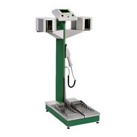
VF HF-350 Instructions For Use Manual (94 pages)
HAND-FOOT CONTAMINATION MONITORS
Brand:
VF
| Category:
Measuring Instruments
| Size: 3 MB
Table of Contents
Table of Contents
4
Tab. 1 EU Guidelines and Government Orders
13
Tab. 2 Technical Standards
13
Fig. 1 Hand-Foot Contamination Monitor
25
Tab. 3 Overview of Monitor Types
26
Fig. 2 Structural Lay-Out
27
Fig. 3 Supply, Protective and Communication Elements at the Back of the Instrument Base
27
Fig. 4 Upper Box with Electronics
28
Fig. 5 Voice Module
28
Fig. 6 Dimensions of the Variant with Vertical Layout of Hand Detectors
29
Fig. 7 Terminal Connectors on the Rear Side of the Box with the PLC
30
Fig. 8 Terminal Connectors on the Back of the Base
30
Tab. 4 Terminal Connectors
30
Storage
32
Installation
32
Fig. 9 Location of the Main Switch on the Back of the Base of the Instrument and Variant with Grommet
32
Tab. 5 Description of the Terminal Board XC1
33
Operation Verification
34
Instrument Actuation
34
Fig. 10 Removal of the Cover at the Back Part of the Base and Actuation of the FZ1 Breaker
34
Fig. 11 Adjustable Legs for Proper Positioning of the Instrument
34
Version with an Identification Card Reader
35
Turning off
35
Power Failure
35
Fig. 12 Display - Basic Screen
35
Fig. 13 Display - Identification of the Measured Person
35
Calibration of the PLC Screen
36
Initial Instrument Settings
36
Fig. 14 Calibration Screen
36
Instructions for Use
37
Visual and Acoustic Signalization
37
Fig. 15 Visual Signalization
37
Tab. 6 Significance of Visual Signalling Statuses
37
Control Elements
38
Basic Screen
38
Fig. 16 Basic Screen - Ready for Measurement
38
Fig. 17 Signal of Readiness for Measurement
38
Contamination Measurement Procedure
39
Fig. 18 Display - Instructions for the Correct Measurement Position
39
Fig. 19 Display - Measurement in Progress
40
Fig. 20 no Contamination Detected
40
Fig. 21 Visual Signalling - no Contamination Detected
40
Fig. 22 Contamination Signalled
40
Fig. 23 Display - Measurement Not Completed
41
Fig. 24 Display - Monitor Contamination Test
41
Contamination Detection by Frisker
42
Fig. 25 Frisker
42
Fig. 26 Detection of Contamination by Frisker - NOT CONTAMINATED
42
Fig. 27 Detection of Contamination by Frisker - CONTAMINATED
42
Display of Measurement Results
43
Fig. 28 Display - Access to the Measurement Results
43
Fig. 29 Display - Measurement Results
43
Service Menu
44
Fig. 30 Display - Enter to the Service Menu
44
Tab. 7 Meanings of the Columns in the Table of Measurement Results
44
Fig. 31 Display - Access to the Service Menu
45
Fig. 32 Display - Service Menu Options
45
Export Archive, Export Errors
46
Fig. 33 Display - Service Menu
46
Fig. 34 Display - Export Archive in Progress
47
Tab. 8 Text File Format of the Archive Exported
47
Clear Archive, Clear Archive of Error
48
Tab. 9 the Meanings of Bits of the Contamination Measurement Bit Mask
48
Tab. 10 the Meanings of Bits of the Contamination Measurement Bit Mask for the Given Detector
48
Configuration Export
49
Fig. 35 Display - Clear Archive
49
Fig. 36 Display - Clear Error Archive
49
Configuration Import
50
Fig. 37 Display - Configuration Export
50
Date and Time
51
Fig. 38 Display - Configuration Import
51
Fig. 39 Display - Date and Time Setup
51
Ethernet Setup
52
Detectors Status
52
Fig. 40 Display - Network Connection Setup
52
Fig. 41 Display - Detectors Status
52
Detectors Response
53
Tab. 11 the Meanings of Values in the Table with the Status of Detectors
53
Reset
54
Fig. 42 Detector Response
54
Instrument Settings
55
Setting the Measurement Parameters by Means of the VF-Setup Service Software
55
Fig. 43 VF-Setup: Setting the Communication
55
Setting the Measurement Parameters by Means of Web Interface
56
Fig. 44 Web Interface Login Form
56
Fig. 45 Web Interface - Menu
57
Instrument Settings
58
Fig. 46 Web Interface - Device Parameters
58
Fig. 47 Web Interface - Device Parameters
58
Tab. 12 Web Interface - Device Parameters
59
Detectors Settings
60
Fig. 48 Web Interface - Detectors Settings
60
Tab. 13 Web Interface - Detectors Settings
61
Maintenance and Care of the Instrument
62
Daily Maintenance
62
Quarterly Maintenance
62
Annual and Multi-Annual Maintenance
62
Protective Foils of Foot Detectors
63
Fig. 49 Foil in a Cardboard Frame Measurement for Alpha Radiation
63
Fig. 50 Optional Accessories - Foot Detector Protective Foil or Frame with a Protective Foil
63
Cleaning the Dirt Tray for Hand Detectors
64
Fig. 51 Orientation of Protective Foil on a Paper Reel
64
Fig. 52 Protective Foil in a Frame on the Foot Detector (with Open Protective Grid)
64
Fig. 53 Cleaning the Dirt Tray for Hand Detectors
65
Checking the Switches for Foot Detector Grates
66
Fig. 54 Foot Detectors Basic Maintenance
66
Metrological Traceability
67
Photomultiplier (PMT) Life
68
Fig. 55 Photomultiplier
68
Fig. 56 Typical Dependence of the Anode Current of the Photomultiplier over Time
68
Troubleshooting
69
Fig. 57 Display - Example of Failure Report
69
Tab. 14 Failure Reports
70
High Background Level
71
Fig. 58 Display - High Background Level
71
Possible Detector Contamination
72
Fig. 59 Display - Detector Contamination
72
Communication Failure
73
Fig. 60 Display - Loss of Communication with a Detector
73
Tab. 15 Detectors & Addresses
73
Delivery Parts
74
Standard Delivery Parts
74
Accessories, Additional Equipment and Related Products Delivered Separately
74
Consumable Material
74
Tab. 16 Standard Delivery Parts
74
Tab. 17 Accessories and Additional Equipment Delivered Separately
74
Tab. 18 Consumable Material
74
Warranty Conditions
75
Annexes
77
Annex A. Block Diagram of the HF Monitor
77
Fig. 61 Block Diagram of the HF Monitor
77
Annex B. Spare Parts for Authorized Service Organization
78
Annex C. Minimum Settable Alarm Level Versus Background Count Rate
80
Fig. 62 Background-Time Dependence of MDA
80
Annex D. I/O Technology
81
Fig. 63 Diagram of the I/O Connector
81
Tab. 19 Connection of an I/O Connector for Technology
81
Annex E. Configuration File
82
Fig. 64 the "Config.xml" Sample Configuration File
82
Annex F. Detector Status, Detector Supply, HV Sources
83
Tab. 20 Global Status of the Detector
83
Tab. 21 Status of the Detector´s Supply
83
Tab. 22 Status of HV Source
83
Annex G. Unpacking Instructions
84
Annex H. Packing Instructions
88
Notes
94
Advertisement
Advertisement
Related Products
VF HF-50
VF HF-100
VF HF-150
VF HF-300
VF HF-4A
VF HF-4B
VF HF-4C
VF HF-4D
VF HF-4E
VF K0950
VF Categories
Controller
Measuring Instruments
Data Loggers
Water Heater
More VF Manuals
Login
Sign In
OR
Sign in with Facebook
Sign in with Google
Upload manual
Upload from disk
Upload from URL