Table of Contents
Advertisement
PORTABLE ACTIVITY METERS
PAM-100A, PAM-100B, PAM-100C, PAM-100D, PAM-100E
PAM-170A, PAM-170B, PAM-170C, PAM-170D, PAM-170E
Types: K0950, K0951, K0952, K0953, K0954,
K1230, K1231, K1232, K1233, K1234
Instructions for Use
VF,a.s.
Svitavská 588
CZ 679 21 Černá Hora
tel. +420 516 428 611
fax +420 516 428 610
info@vfnuclear.com
www.vfnuclear.com
VF1706050120 EN
2015revision H
VF1706050120 EN
revision H
version 10
2017
Advertisement
Table of Contents

Related Manuals for VF PAM-100A

Summary of Contents for VF PAM-100A
- Page 1 PORTABLE ACTIVITY METERS PAM-100A, PAM-100B, PAM-100C, PAM-100D, PAM-100E PAM-170A, PAM-170B, PAM-170C, PAM-170D, PAM-170E Types: K0950, K0951, K0952, K0953, K0954, K1230, K1231, K1232, K1233, K1234 Instructions for Use VF1706050120 EN VF,a.s. Svitavská 588 revision H CZ 679 21 Černá Hora tel. +420 516 428 611...
- Page 2 VF1706050120 EN 2015revision H...
- Page 3 2.Occupational safety, fire protection and environmental impacts ....13 2.1. Occupational safety 2.1.1 Safety signs used in VF, a.s. and their meanings ..............13 2.1.2 Obligations of the operator ....................13 2.1.3 Qualification requirements of the staff ................13 2.1.4 Conditions for the safe operation of electrical equipment ............. 13 2.2.
- Page 4 Turning OFF 7.Instrument settings ..................38 7.1. Instrument presets 7.2. Setting the measurement parameters by means of the VF-Setup service software Setting the communication with the VF-Setup service software: 8.Maintenance and care of the instrument ............40 8.1. Daily maintenance 8.2.
-
Page 5: Table Of Contents
Table of Contens 10.1. Standard delivery parts 10.2. Accessories, additional equipment and related products delivered separately 10.3. Consumable material 11.Warranty conditions ..................45 12.Annexes ......................47 Annex A. Presets´default settings .................... 47 Notes ........................49 VF1706050120 EN revision H... - Page 6 Fig. 17 Exceeding of measurement range ................36 Fig. 18 Failure display ......................37 Fig. 19 VF-Setup: Setting the communication ................39 Fig. 20 Photomultiplier ......................42 Fig. 21 Typical dependence of the anode current of the photomultiplier over time ...... 42 Fig.
- Page 7 Tab. 12 List of accessories, additional equipment and associated products ........ 44 Tab. 13 Consumable material ....................44 Tab. 14 Default settings PAM-100A, PAM-170A ............... 47 Tab. 15 Default settings PAM-100B, PAM-100D, PAM-170B, PAM-170D ........47 Tab. 16 Default settings PAM-100C, PAM-100E, PAM-170C, PAM-170E ........48 Tab.
- Page 8 Read the Instructions for Use carefully before using the PAM Portable Activity Meter and follow its suggestions. The information contained in these Instructions for Use is the exclusive property of VF, a.s., and may not be modified, copied or disclosed to third parties without the company's knowledge.
- Page 9 Introduction Introduction The PAM-100 series meters are portable hand-held instruments intended for the measurement of surface contamination by alpha, beta and gamma emitting radionuclides. It is a compact and ergonomically designed user-friendly meter. 1.1. Abbreviations Activity Surface activity Certified reference material Detection limit Decision threshold Coefficient of the error of the first kind (instrument reports a false positive alarm)
- Page 10 Introduction 1.2. Terms and definitions A quotient of the mean number of spontaneous nuclear transitions from an energy Activity state in an amount of radionuclide in a time interval. The unit is [Bq]. Alarm level Value (threshold) that is preset inside the instrument. If this value is exceeded, the alarm will be activated.
- Page 11 Introduction Indirect evaluation of Assessment of removable contamination by means of wipe (smear, swab) test surface contamination samples. Instrument response Ratio of the corrected count rate of the measuring instrument to the measured quantity (activity, surface activity, dose rate, etc.). The unit of response to activity is usually [cps/Bq], to surface activity [cps/(Bq∙cm )] and to dose rate [cps/(Sv/h)],[cps/(Gy/h)].
-
Page 12: Tab. 1. Eu Guidelines And Government Orders
Introduction 1.3. Acts, regulations and standards The acts, regulations and standards provided herein are valid in the European Union. The instrument meets and follows the directives and government regulations referred to in Tab. 1 as well as the harmonized technical standards referred to in Tab. - Page 13 Occupational safety A summary of measures laid down by legislation and recommended by the producer that should prevent risk or detriment to human health in work. 2.1.1 Safety signs used in VF, a.s. and their meanings Attention, electrical equipment. Information, recommendations The appliance is supplied by AC voltage and comments of the manufacturer.
- Page 14 When disposing of the instrument after the expiration of its life, you must follow applicable local legislation VF, a.s. is involved in the RETELA collective take-back system for the manufacturers of electrical instruments. For more information on the RETELA system, please visit http://www.retela.cz/ as well as http://www.weee-forum.org/.
- Page 15 Technical specification Technical specification Portable Activity Meter PAM-100A PAM-100B PAM-100C PAM-100D PAM-100E Type K0950 K0951 K0952 K0953 K0954 Portable Activity Meter PAM-170A PAM-170B PAM-170C PAM-170D PAM-170E Type K1230 K1231 K1232 K1233 K1234 Only figures with tolerances or limits are guaranteed data; any other values are only informative.
-
Page 16: Tab. 3 Detectors Specification
PAM-100D: Alpha + Beta + Gamma in one channel PAM-100E: Alpha / Beta + Gamma in two channels PAM-100A: ZnS(Ag) on acrylic glass, 1.5 mm thickness. Surface density of scintillator (3.25 ± 0.25) mg∙cm PAM-100B: plastic scintillator of 0.25 mm thickness PAM-100C: ZnS(Ag) on plastic scintillator of 0.25 mm thickness. -
Page 17: Tab. 4 Radiometric Parameters Of Detector Series Pam-100
Technical specification Parameter Instrument Measurement range Response to background PAM-100A 4 cps to 150 kcps < 0.04 cps, typically 0.02 cps PAM-100B 6 cps to 150 kcps < 10 cps, typically 5 cps PAM-100C (alpha) 4 cps to 150 kcps <... -
Page 18: Tab. 5 Detectors Specification
Technical specification 3.2. PAM-170 series: PAM-170A, PAM-170B, PAM-170-C, PAM-170D, PAM- 170C, PAM-170E PAM-170A: Alpha in one channel PAM-170B: Alpha + Beta in one channel Detected radiation PAM-170C: Alpha / Beta in two channels PAM-170D: Alpha + Beta + Gamma in one channel PAM-170E: Alpha / Beta + Gamma in two channels PAM-170A: ZnS(Ag) on acrylic glass, 1.5 mm thickness. -
Page 19: Tab. 6 Radiometric Parameters Of Detector Series Pam-170
Technical specification Parameter Instrument Measurement range Response to background PAM-170A PAM-170B PAM-170C (alpha) 4 cps to 100 kcps < 0.3 cps, typically 0.15 cps Measurement ranges PAM-170C (beta) 6 cps to 100 kcps < 12 cps, typically 6 cps Response to background indicated for 100 nGy/h PAM-170D PAM-170E (alpha) -
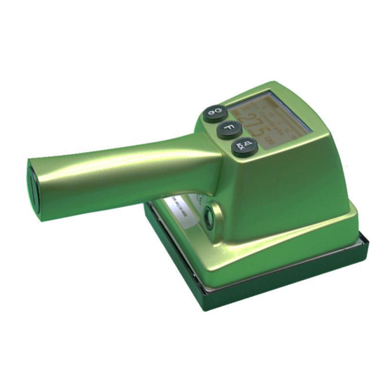
Page 20: Fig. 1 Portable Pam Series Meters
The instruments in both series have a unified design. The individual types have different scintillators used, metrological parameters and software settings. PAM-100A, PAM-170A are single-channel instruments optimized for the measurement of alpha radiation emitting radionuclides. The radiation detector is ZnS(Ag) scintillation material coated on an acrylic glass board. -
Page 21: Tab. 7 Suitability Of Pam Meters For Different Kinds Of Radiation
The instruments are characterised by their good efficiency of alpha radionuclides detection, good efficiency for beta and gamma radiation, and low crosstalk between channels, even at high count rates. Portable Activity Meters Alpha Beta Gamma PAM-100A, PAM-170A ● PAM-100B, PAM-170B ◌ ● PAM-100C, PAM-170C ◌... -
Page 22: Fig. 2 View Of The Detector And Its Protective Cover
General description that the final values are free of such effects and the instrument’s operator can fully concentrate on the activity performed. The measured value is clearly shown on a graphical LCD display in the form of a bar graph and figure. The instrument is equipped with a piezo-siren enabling it to indicate detected counts, button pressing and the exceeding of the selectable alarm levels. -
Page 23: Fig. 3 View Of The Instrument With The Protective Detector Cover In Place
General description Fig. 3 View of the instrument with the protective detector cover in place A graphic LCD display and three control buttons are located at the top part of the body. The siren is directed towards the instrument user, and it is located next to the handle. The display, buttons and siren have a higher degree of electrical protection, which enables the cleaning of the instrument with decontamination agents (see Chapter 9.1). -
Page 24: Fig. 5 Installation Of The Battery In The Instrument
General description Fig. 5 Installation of the battery in the instrument The batteries are installed inside the hollow handle. The handle is closed with a cap. Batteries are inserted in the handle with the positive pole (the protrusion on the battery front) first. There is no risk of damage to the instrument if the batteries are inserted incorrectly (polarity changed). -
Page 25: Fig. 7 Basic Dimensions Of The Pam-170 Series
General description Fig. 7 Basic dimensions of the PAM-170 series 4.5. Operating the instrument The instrument is controlled by means of three buttons. The functions are arranged in such a way that control is as simple as possible. Acoustic ON, OFF, back indication illumination Presets,... - Page 26 Before putting the instrument into operation Before putting the instrument into operation 5.1. Transportation Do not expose the instrument to mechanical shocks and vibrations to which the PMT used in the detector is sensitive. The instrument is transported in an assembled state; it is only necessary to insert batteries. ...
- Page 27 Prior to putting into operation, check and, if necessary, adjust the instrument parameters using the VF-Setup software, see Chapter 7.
-
Page 28: Fig. 9 Control Overview
Instructions for use Instructions for use 6.1. General Prepare the instrument for operation and switch on in accordance with Chapter 5. While transporting to the place of use, it is advisable to protect the detector against damage using a protective cover (see Fig. 3). 6.2. -
Page 29: Fig. 10 Example Of The Display Of Instrument Initialization
Instructions for use 6.2.1 Turning ON / OFF The left button is used to switch the instrument off and on and to control the display’s back illumination. The instrument is switched on by pressing the button briefly. It is switched off by pressing the left button for two seconds. -
Page 30: Fig. 11 Description Of Elements On The Screen (Example)
Instructions for use 6.3. Working screen Value in bar graph Bar graph scale with prefixes Kind of radiation detected Preset text Acoustic alarm disabled symbol Alarm level 1(2) exceeding symbol Battery Numerical Numeric value Unit common for numerical value indicator value prefix and bar graph... -
Page 31: Fig. 13 Battery Status Examples (From The Left: Discharged, Partly Discharged, And Fully Charged)
Instructions for use Prefix Value 1E-9 μ 1E-6 1E-3 1E+3 1E+6 1E+9 Tab. 8 Supported prefixes Unit Possible prefixes k, M Cps/cm K, M k, M m, k, M, G Bq/cm m, k, M, G Bq/m m, k, M, G Gy/h n, μ, m, k Sv/h... -
Page 32: Fig. 14 Example Of Display When Working With The Background Reading Function
Instructions for use 6.4. Preset selection One of the initial presets, typically a radionuclide, to which the preset response factor for the currently displayed value and the applicable unit apply, can be selected on the instrument, for more information see Chapter 7.1. - Page 33 Instructions for use The monitor is in normal operating mode: After that: Long press the F button to activate the mode of working with the background. 2. In the mode, long press the F button again to start background measurement. A bar graph and a sign "Measuring"...
- Page 34 Instructions for use b) Shortly press the F button to return to the normal mode. 4. Background reset: a) Long press the F button to move to the mode of working with the background. b) Shortly press the F button to display a sign "Reset?". c) To save, long press the F button, "Saved"...
-
Page 35: Fig. 15 Acoustic Signal Mute Symbol
Instructions for use 6.6. Acoustic signalization The instrument uses the acoustic signals for two different situations: A) During measurement, the instrument allows acoustic signalling of detected ionizing radiation (pulses generated by the detector). This signal can be switched off (disabled). Disabling / enabling the acoustic signalling for detected radiation is controlled by pressing the right button repeatedly. -
Page 36: Fig. 16 Alarm Level Exceeded Symbols On The Display
Instructions for use 6.7.1 Alarm level exceeding None, one or two alarm levels in the units, which correspond to a given preset, can be defined in each preset. An alarm level being exceeded is indicated by the instrument visually on the display, as well as acoustically. If two alarm levels are defined, it is assumed that the Alarm 2 Threshold has a higher value than the Alarm 1 Threshold. -
Page 37: Fig. 18 Failure Display
Instructions for use The symbol of alarm exceeded, if any, is displayed next to the unit, see Chapter 6.7.1. 6.8. Failure indication Any failure detected by the instrument is indicated with the text "ERR" in the place of the numerical value. For troubleshooting, see Chapter 9. - Page 38 Instrument settings 7.1. Instrument presets Using the VF-Setup software (in the configuration for the user), it is possible to define ten presets for the instrument to be shown on the display. Each preset is defined by: a) permission/restriction of a preset,...
-
Page 39: Fig. 19 Vf-Setup: Setting The Communication
Fig. 19 VF-Setup: Setting the communication VF-Setup service software in configuration for users is part of the standard scope of delivery. VF-Setup service software in configuration for service partners can be delivered only to service organizations or to a user's employees authorized by the manufacturer. - Page 40 Maintenance and care of the instrument Maintenance and care of the instrument When performing maintenance and care of the instrument, follow the requirements and principles of work safety, Chapter 2.1. 8.1. Daily maintenance Carry out a visual inspection of the instrument and check its operability. When a high count rate is measured above the ambient background, proceed in accordance with Chapter 9 Troubleshooting.
- Page 41 To maintain the quality of preset metrological parameters with time, do not leave the instrument switched off for longer than three months If the user changes the parameter settings by means of the VF-Setup software in configuration for service organizations, the producer cannot guarantee the accuracy and precision of the displayed quantities of activities or surface activities.
-
Page 42: Fig. 20 Photomultiplier
The time dependence is a routine matter, i.e. the photomultipliers should be sorted for selected applications. Each PMT is tested and assessed in VF as to whether or not its parameters meet the expected requirements. PMT testing and stabilization usually take 48 hours. The chart shows typical dependence of anode current over time. -
Page 43: Tab. 10 Overview Of The Most Frequent Failures
The instrument does not Wrongly attached cable Check connectivity. communicate with service software Incorrectly set root file Check the setting according to the VF S0506-25 document for VF- Incorrectly set instrument Setup. communication Display back illumination blinks Weak battery Change batteries. -
Page 44: 10.1. Standard Delivery Parts
Delivery parts Delivery parts 10.1. Standard delivery parts Item specification Identification (VF stock number) Amount Portable Activity Meter, type according to order According to order 1 pc USB cable (Mini B- A) 1-0216-00036 1 pc Protective case SUPREME 27F 1-1180-00003... -
Page 45: Warranty Conditions
Other warranty conditions are individually agreed in the supply terms and conditions. Please submit your claim in written form by post to the manufacturer’s address or via email to the address servis@vf.cz; include a description of the fault. - Page 46 The instrument is delivered by and the warranty and after- Contact the service partner: warranty service is provided by: Czech Republic: VF, a.s., Svitavská 588, 679 21 Černá Hora Phone: +420 516 42 86 11, Fax: +420 516 42 86 10 e-mail: info@vfnuclear.com.cz, www.vfnuclear.com...
-
Page 47: Annexes
Unit Description, purpose Channel Count rate Countrate measurement 241Am activity Am-241 Bq/cm2 measurements in contact geometry Tab. 14 Default settings PAM-100A, PAM-170A PAM-100B, PAM-100D, PAM-170B, PAM-170D Alarm level Preset On display Unit Description, purpose Channel Count rate Countrate measurement C activity... -
Page 48: Tab. 16 Default Settings Pam-100C, Pam-100E, Pam-170C, Pam-170E
Bq/cm measurements in contact geometry Tab. 16 Default settings PAM-100C, PAM-100E, PAM-170C, PAM-170E Until 2014, PAM-100 series meters were supplied under a different identification (short name): Older identification Current identification PAM-50 PAM-100A PAM-100 PAM-100B PAM-150 PAM-100C PAM-300 PAM-100D PAM-350 PAM-100E Tab. -
Page 49: Notes
Notes Notes VF1706050120 EN revision H...
Need help?
Do you have a question about the PAM-100A and is the answer not in the manual?
Questions and answers