Table of Contents
Advertisement
Quick Links
Advertisement
Table of Contents

Subscribe to Our Youtube Channel
Related Manuals for Ironton 81869


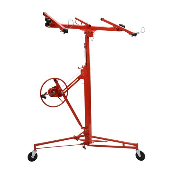
Summary of Contents for Ironton 81869
- Page 1 150-Lb. Drywall and Panel Hoist Owner’s Manual WARNING: Read carefully and understand all ASSEMBLY AND OPERATION INSTRUCTIONS before operating. Failure to follow the safety rules and other basic safety precautions may result in serious personal injury. Item #81869 READ & SAVE THESE INSTRUCTIONS...
- Page 2 Thank you very much for choosing an Ironton™ product! For future reference, please complete the owner’s record below: Serial Number/Lot Date Code: ________________________________ Purchase Date: ____________________________________________ Save the receipt, warranty, and this manual. It is important that you read the entire manual to become familiar with this product before you begin using it.
-
Page 3: Table Of Contents
Table of Contents Intended Use ............................4 Technical Specifications ........................4 Important Safety Information ....................... 4 Specific Operation Warnings ....................... 6 Main Parts of Hoist ..........................6 Assembly Instructions .......................... 7 Before Each Use ..........................11 Operating Instructions ........................11 After Each Use ............................. -
Page 4: Intended Use
Intended Use The Ironton 150-Lb Drywall and Panel Hoist allows one person to lift a drywall panel without assistance. The panel can be raised to a maximum height of 11 feet for attachment to level ceilings-or (with the lift's cradle tilted) to sloped ceilings or side walls. - Page 5 children to handle the product. Be aware of all power lines, electrical circuits, water pipes, and other mechanical hazards in your ⚫ work area. Some of these hazards may be hidden from your view and may cause personal injury and/or property damage if contacted. ⚠WARNING PERSONAL SAFETY Stay alert, watch what you are doing, and use common sense when operating the tool.
-
Page 6: Specific Operation Warnings
Specific Operation Warnings ⚠WARNING To avoid injury, slide bar lock must be fully engaged if winch assembly is extended. ⚫ Wear ANSI Z87.1 compliant safety goggles, hard hat, heavy duty gloves, and steel toed boots ⚫ during setup and use. Do not exceed the rated load capacity. -
Page 7: Assembly Instructions
Assembly Instructions Set Up the Tripod Base 1. Set the base on the floor. 2. Press down the slide yoke ring on the inner leg (1). Hold the ring down while swinging the two outer legs (8) forward until the yoke ring snaps into the locking hole on the bottom of the tube. 3. - Page 8 Frame Assembly Set the frame assembly onto the two "V" angles on the tripod base. The frame must fit over both "V” shaped flanges. The frame assembly must sit exactly vertically. If the frame sits at an angle then the unit is not tucked into the inner "V” shaped flange. Winch Wheel Set-up 1.
- Page 9 • When the winch is fully extended away from the frame, release the brake handle (34) and swing the safety hook (22) away so it no longer secures the telescoping sections inside the frame housing (10). Attach the Cradle to the Frame Assembly 1.
- Page 10 3. Press each crossarm (42) forward into the socket until the spring tab on the bottom of the cross- arm (42) snaps into place. Testing the Assembly 1. With assembly completed, check the panel hoist to be sure all fasteners are tight, the wire rope is in place and undamaged, and the hoist is safe to use.
-
Page 11: Before Each Use
Before Each Use ⚠WARNING Inspect the unit carefully for wear or damage. Pay special attention to the cable. ⚫ Be sure the hoist is at working room temperature before operating. ⚫ Be sure the winch brake drum is clean and dry before operating. ⚫... - Page 12 Extension (46) The extensions on the crossarms extend for supporting a longer drywall panel. For safe use, both extensions should be pulled out the same amount to support the panel equally. To extend, pull out the lock pin with your right hand until you can slide the extension from the end of the cradle beam until it lines up with one of the three holes.
- Page 13 Slide Bar Lock (30) The slide bar lock holds the winch assembly at its operating (fully extended) position. Tilt Pin (15) The tilt pin allows the cradle to tilt to adjust the panel as needed for installation on sloped ceilings or walls.
- Page 14 Attached Pin with Pin Level This is a self-locking device. When lifting a panel, the latch is automatically locked and avoids the sudden fall of the cradle. This is a second insurance against the cradle falling. If the attached pin fails to work, this Secure Square Pin will limit the falling height of the cradle.
- Page 15 Brake Handle (34) A spring-loaded brake holds the cradle at the desired height. Raise it by cranking the winch wheel. To lower the cradle, control the winch’s counter-clockwise rotation by grasping the handle and carefully raising the brake arm to release the brake. Operating Procedures To Load a Drywall Panel: •...
-
Page 16: After Each Use
• Crank the winch wheel clockwise to raise the panel slightly, then stop, checking that the brake is functioning properly. Slide the secure square pin through the inner pin holes above the telescoping section. • If the brake is functioning properly, resume raising the panel to the desired height. Slide the secure square pin through the inner pin holes above the telescoping section. -
Page 17: Maintenance
Maintenance ⚠WARNING Do not lubricate any part of the winch components. The brake is friction-based and may fail if lubricated. Maintain the hoist by adopting a program of conscientious repair and maintenance in accordance with the following recommended procedures. It is recommended that the general condition of any tool be examined before it is used. -
Page 18: Parts Diagram
Parts Diagram Page 18 of 23... -
Page 19: Parts List
Parts List Reference Part Description Quantity Leg, Inner Pull Spring A Rivet Flat Washer Ø12 Cotter Pin Ø2.5×25 Support Rod Leg, Outer Lock Caster Frame Housing Telescoping Section, Outer Telescoping Section, Inner Mounting Pin Hinge Pin Tilt Pin Mini Chain Ring Press Plate Bolt M6 x40... - Page 20 Reference Part Description Quantity Brake Handle Cover Winch Wheel Long Bushing Bolt M10x150 Lock Nut M10 Handle Cradle Beam Crossarm Pin Ø5 Spring Retaining Ring Ø5 Extension End Cap Flat Washer Ø12 Winch Handle Bolt M12x115 R Pin Lock Spring Square Pin Partial Post Round Tube Cap...
-
Page 21: Replacement Parts
Replacement Parts • For replacement parts and technical questions, please call Customer Service at 1-800-222-5381. • Not all product components are available for replacement. The illustrations provided are a convenient reference to the location and position of parts in the assembly sequence. •... -
Page 22: Limited Warranty
Northern Tool and Equipment Company, Inc. ("We'' or ''Us'') warrants to the original purchaser only (''You'' or ''Your'') that the Ironton product purchased will be free from material defects in both materials and workmanship, normal wear and tear excepted, for a period of one year from date of purchase. - Page 23 Distributed by: Northern Tool & Equipment Company, Inc. Burnsville, Minnesota 55306 www.northerntool.com Made in China Page 23 of 23...
Need help?
Do you have a question about the 81869 and is the answer not in the manual?
Questions and answers
where can I buy a replacement caster for the ironton model 81869 drywall hoist?
You can find a replacement caster for the Ironton model 81869 drywall hoist by calling Customer Service at 1-800-222-5381.
This answer is automatically generated