
Related Manuals for Cooper Scantronic 8136UK-50


Summary of Contents for Cooper Scantronic 8136UK-50
- Page 1 INSTALLATION AND PROGRAMMING GUIDE 8136UK-50/75 HARDWIRED CONTROL PANEL Leading the way in security...
- Page 2 8136 Hardwired Control Panel Installation and Programming Guide. © Scantronic Ltd. 2000 Every effort has been made to ensure that the contents of this book are correct. However, neither the authors nor Scantronic accept any liability for loss or damage caused or alleged to be caused directly or indirectly by this book. The contents of this book are subject to change without notice.
- Page 3 Contents 1. Overview 2. Technical Specification 3. Installation 4. Programming 5. Programming for IDIS 6. Programming Examples 7.Programming Reference 8. Communications 9. Testing 10. Fault Finding Index...
- Page 4 How To Use This Book This book is divided into the following sections: 1: Overview gives a brief introduction to the 8136. 2: Technical Specification lists the physical capabilities of the system, and gives part numbers for compatible equipment. 3: Installation provides step by step instructions for physically installing the 8136 end station and its keypads, wiring Fully Supervised Loop (FSL) sen- sors, connecting sounders, and wiring IDIS devices.
-
Page 5: Table Of Contents
Contents 1. Overview ....................1 Control Unit ....................2 Keypads ....................... 3 The 931 Keypad ........................3 The 930 Low Profile Keypad ....................3 2. Technical Specification ................5 General ..........................5 Power Supply ......................... 5 Output Protection ......................5 Battery .......................... - Page 6 4. Programming ..................35 Programming Mode ......................35 Finding Menu Items ....................... 35 Changing Menu Items ......................36 Correcting mistakes ....................... 36 Entering Text ........................36 Leaving Programming Mode ....................37 To Return to the ‘All Level Unset Mode’ From Programming .......... 37 Engineer Reset ........................
- Page 7 Menu Options ..................... 76 Menu 01 - Display Panel Version Number ................77 Menu 04 - Test Options ......................77 Menu 09 - Print Options ....................... 77 Menu 11 - Edit Name (Account Name) ................. 77 Menu 21 - Zone Expander Options ..................77 Menu 22 - IDIS Programming ....................
- Page 8 Installation ....................109 Safety notice ........................109 Fitting a Plug On Communicator ..................110 9076-01 Interface ......................111 9076-02 Interface ......................111 Connecting the Telephone Line ................... 111 Programming for Central Station .............. 113 Communications Options (Menu 71) ................... 113 Phone Numbers and Account Numbers (Menu 72): ............
-
Page 9: Overview
1. Overview 1. Overview The 8136 is a programmable Alarm System that can be expanded up to 136 zones and is suitable for large residential and business premises. The system comprises an control unit in a shielded case, and up to fifteen separate keypads. -
Page 10: Control Unit
1. Overview Control Unit Figure 1 below shows the control unit PCB. Use the diagram to familiarise yourself with the location of the connectors, reset and kick start pins. Expander Card Plug-on Communicator 942 IDIS Expander Card 941 IDIS Expander Card Communications Serial Port RJ11 phone... -
Page 11: Keypads
1. Overview Keypads The 931 Keypad The 8136 uses the 931 low profile keypad, shown in Figure 2. Level A to D LEDs (Set or Unset) 32 Character plain text Liquid Crystal Display Power Optional programmable panic alarm keys. Press Scroll and Level keys 1 and 3 together setting keys... - Page 12 1. Overview Figure 4 shows the keypad PCB used in the 930 and 931. Note the position of the Test and Prog switches, and the keypad sounder volume control. Prog and Test Sounder Volume Back of display Prog Control Test Sounder Key area Micro...
-
Page 13: Technical Specification
2. Technical Specification 2. Technical Specification General Operating temperature = -10º to +55ºC Humidity = 80% RH Dimensions (control unit) = h x w x d 310 x 385 x 95mm Weight (control unit) = Approximately 7Kg Power Supply System Power Supply (Ambient Temp. -
Page 14: Fsl Zone Wiring
2. Technical Specification For a daisy chain configuration the maximum length must take account of the number of keypads sharing the cable. In general, a single keypad can be connected at the end of a maximum of 300 meters of standard cable. If you wish to connect more keypads the cable must be shorter, or the 0V wire must be thicker. - Page 15 2. Technical Specification Portable printer ( Battery powered ) and power supply unit Wall Mounted Printer Bracket Scantronic high speed <Downloader> Windows™ based software Printer lead (supplied with 947 Printer) 9040 16 Ohm internal sounder 9056 Plug-on Digital Communicator Plug-on RedCare STU (manufactured by others) 9076-01/2 Signalling Interfaces Wired IDIS Module (Pack of 5)
- Page 16 2. Technical Specification 496310...
-
Page 17: Installation
3. Installation 3. Installation These installation instructions assume that you have already identified the locations of the detectors, keypads, sounders and control unit, and run suitable cable to each position. Then: Install the control unit. Address, install and connect at least one LCD keypad. Install all conventional detectors, external and internal sounders, etc. -
Page 18: Fitting The Control Unit
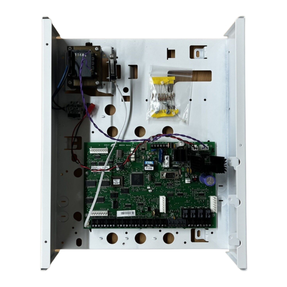
3. Installation Fitting the Control Unit Remove the screws from the control unit cover and lift the cover off. Figure 5 shows the inside of the control unit. Mains Fused terminal (Euro 20mm type) Main PCB Fixing hole Keyhole knockouts Transformer Lid Tamper Switch 20 mm... -
Page 19: Battery
3. Installation control unit, then drill and plug the two bottom holes. Continue to fix the control unit using not less than No. 10 pan head screws. Battery The control unit has space for a 17Ah sealed Lead Acid battery. See Figure 5 for location. -
Page 20: Keypads
3. Installation Keypads NOTE: The Installer must program an identification number into the NVM chip on each keypad before connecting it to the system. Each keypad in a system must have a different address number to ensure that the control unit can correctly identify them. -
Page 21: Display Test (Optional)
3. Installation 11. Change the key status as required by entering 0 or 1. (The keypad keys are normally left active = ‘ZERO’.) 12. Repeat 2 to 11 for any other keypad. 13. Set the ‘Prog’ switch to OFF and remove power to the keypads to lock the address and options into the keypad(s). -
Page 22: Fitting A 930
3. Installation Scantronic recommend that you mount the keypad using No 8 or 6 screws (M4/M3.5) as follows: Select which cable entry you are going to use and break out the appro- priate plastic sections. Hold the backplate in place against the wall and mark the position of the centre hole in the adjustable cam (see Figure 7). -
Page 23: Wiring
3. Installation Wiring The 8136 control unit PCB has facilities for connecting: Fifteen keypads. Eight 2-wire FSL detector zones. Siren (4-speaker 16 ohm). Four outputs. If you wish to connect extra detector zones you can fit either an eight zone FSL Expander Card, or 32- or 128- zone IDIS Expander Cards. -
Page 24: Wiring Keypads
3. Installation Wiring Keypads All keypads must be connected either to Keypad terminals on the main PCB or "daisy chained" to other keypads. Figure 10 shows the connections. Prog Display Test Micro Rear of keypad pcb N/O Exit Terminate Button or N/C Lock Set Switch Extension Piezo... - Page 25 3. Installation end of the wired loop (EOL-End-Of-Line), and a 4K7 (4.7K ) resistor fitted across the alarm contact, see Figure 11. Alarm contacts Zone 1 2k2 EOL Tamper Loop Figure 11. Connections for Single Alarm Contacts and Tamper Wiring. With the loop in a normal state and the alarm contacts closed (shorting out the 4K7 resistor), the total resistance of the loop is 2K2 .
-
Page 26: Wiring External Sounders
3. Installation Figure 14 shows the method for connecting foil, batten frames or lace wiring. Zone 1 Positive leg Foil or CC wire Negative leg Foil or CC wire Figure 14. FSL Connections for Foil, Batten Frames or Lace Wiring. An additional eight conventional FSL zones may be added by fitting an eight zone FSL plug-on expander board. -
Page 27: Internal Sounders In Multi-Partition Systems
3. Installation connection on the control unit. If more than one external sounder is being connected, then consult the sounder manufacturer on how to wire the tamper return circuit. Bell Note: Leave disconnected if Typical SAB EOL method is being used. Bell End Station -ve Tamper Return... - Page 28 3. Installation Zone 1 Zone 1 Full Part Full Set and Off Part Set and Off Figure 17. Two Position On/Off Keyswitch Zone 1 Figure 18. Momentary Keyswitch Part Zone 1 Full Figure 19. Three Position Part/Full Set Keyswitch. Full Zone 1 Part Full...
-
Page 29: Wiring A Lighting Control Zone
3. Installation Figure 21 shows how to connect a ready lamp on a keyswitch. See "6. Programming Examples- Example 6 Keyswitches" for details of program- ming the output. Aux DC Keyswitch Ready Lamp Programmable output Figure 21. Connecting a Ready Lamp on a Keyswitch Wiring a Lighting Control Zone To wire a switch used for Lighting Control onto a FSL zone, fit a 2K2 (2.2K... -
Page 30: Connecting A Printer
3. Installation Connecting a Printer Connect a printer to the three-pin printer connector on the 8136 main pcb, See "1. Overview - Figure 1". The three pin connection is designed to drive any compatible serial printer unit (for example the Scantronic 947). The print connector output is formatted at 4800 Baud, 8 bits, even parity and one stop bit. -
Page 31: Wiring Idis Detectors
3. Installation Wiring IDIS Detectors If you wish to use IDIS sensors, then you must fit an IDIS Expander card to the control unit main PCB. Figure 24 below shows the layout of an IDIS expander card. 942 IDIS Expander 941 IDIS Expander IDIS Loop 4 zones 105 - 136... - Page 32 3. Installation To other IDIS sensors Optional 907 Remote PSU IDIS Module IDIS Expander Card To other IDIS sensors To other IDIS sensors Figure 26. IDIS Star Wiring Figure 27 shows a ‘Ring’ configuration for the IDIS bus. Both ends of a single cable are connected to one loop at the IDIS Expander card.
-
Page 33: Maximum Idis Cable Lengths
3. Installation Maximum IDIS Cable Lengths For any single IDIS loop the maximum recommended cable length, includ- ing spurs, is 500m. If you are going to install the maximum length of cable then check that the voltages at the farthest detector are within the following limits: 12V and 0V lines not less than 12V Sig and 0V lines not less than 7V. -
Page 34: Wiring Idis Devices
3. Installation Wiring IDIS Devices Note: Ensure that you program each IDIS device or module with a zone number BEFORE finally installing it. See "4. Programming" for instructions on how to enter programming mode, and "5. Programming IDIS Devices". Figure 29 below shows the wiring for IDIS sensors. -
Page 35: Idis Switched I/O Devices
3. Installation IDIS Switched I/O Devices If you wish to control external devices from outputs of the 8136 control unit then you can connect the 903 Mains AC Switcher I/O unit for controlling mains powered devices, or 904 Low Voltage Switcher I/O unit for devices that use 12VDC power. - Page 36 3. Installation Green Purple White CC Tamper loop Yellow Black IDIS Module Blue CC Alarm loop +12V Brown Open Collector Output IDIS Expander Card To other IDIS units +12V Non-IDIS Sensor IDIS Output max 25mA IDIS Module Tamper loop Alarm loop Figure 31.
-
Page 37: Wiring Keyswitches To Idis Zones
3. Installation See separate 908 Installation Note: Use only one 4k7 resistor Guide for more details. per circuit connection. Alarm contact FSL Loop cct 7 2k2 EOL Tamper Loop Tamper switch and pins Open Collector Outputs Load 100mA @ Each Output 500mA total from all 8 outputs. -
Page 38: Wiring A Lighting Control Switch To An Idis Zone
3. Installation Two Position Keyswitch (momentary example) Three Position Part Keyswitch (fixed example) Full Armed Lamp COMM Ready lamp COMM PROG Figure 33. Wiring Keyswitches to IDIS Zones Wiring a Lighting Control Switch to an IDIS Zone If fitting a Lighting Control switch to an IDIS zone, connect the switch across the alarm loop. -
Page 39: Initial Power Up
3. Installation Initial Power Up Battery Only (Kick Start) When powering the control unit from a battery for programming and testing (a typical site situation with no mains available), it is necessary to short out the ‘Kick Start’ pins with a small screwdriver to connect the battery and allow operation of the system. - Page 40 3. Installation Press Enter until the display prompts to remove the control unit lid: REMOVE END STATION LID Note: The system may be programmed so that you do not have to operate the control unit Tamper Switch. See "7. Programming Reference - Menu 67". If the control unit Tamper Switch is already open, close and open it again.
-
Page 43: Programming
4. Programming 4. Programming Note: If you are powering up the system for the first time then see "3. Installation - Initial Power Up". Programming Mode To enter Installer Programming Mode: The display shows the date and time: WED 15 JAN 1997 09:00 Key-in 0 (zero) followed by the Installer code (default 7890 or 567890), then press Menu. -
Page 44: Changing Menu Items
4. Programming For a complete list of Menus and options see the fold out sheet at the begin- ning of this section. Changing Menu Items After selecting a menu, press Enter to see further options belonging to that menu. The system usually displays the name of the option on the top line, and the values the option currently has on the bottom line of the display. -
Page 45: Leaving Programming Mode
4. Programming arrow key (D on the 931) to move the cursor to the next space for a new letter. If you make a mistake, use the left or right arrow keys (C or D) to move the cursor over the letter you want to change, and key in the new letter. If you want to delete a name completely, use the left arrow key (C) to move the cursor under the extreme left hand character of the name. -
Page 46: Engineer Reset
4. Programming Press Menu. If the control unit lid is open, the displays shows:REPLACE END STATION LID Note: The system can be programmed so that it does not ask for the Control unit Lid to be removed. See "7. Programming Reference - Menu 67". Close the control unit lid. -
Page 47: Return To Factory Defaults
4. Programming In addition, the system: Disallows remote set/unset. Unlocks any lockout imposed by Downloader. Clears any message that may have been sent by Downloader. Re-initialises communications with all keypads. The remaining programming is unchanged. Return to Factory Defaults If you need to return the control unit to factory defaults (no programming and an empty log) then: Follow steps 1 to 4 in "Resetting User and Installer Codes". - Page 48 4. Programming (The system may display the PLEASE WAIT message for several seconds while it loads defaults.) The control unit now has the full set of Scantronic factory defaults (including 4 or 6 digit access codes depending on country) and needs reprogramming. Note: If you remove power during programming, and you have not created a valid configuration, then the system will force you to enter programming mode when you reapply power.
-
Page 49: Programming For Idis
5. Programming for IDIS 5. Programming for IDIS When installing IDIS devices, you must program them with a zone number before wiring the devices in position. To do this you can use the control unit or the Handheld IDIS Programmer. Make sure that you record the zone number you have given each device. - Page 50 5. Programming for IDIS way Molex to Molex lead 485206 and connect the other end onto the pins marked 'PROG' on the device. Ensure that the BLUE lead is located on the pin marked with a star (*). OR: For LIMs with a 2-pin Prog connector use 3-way to 2-way Molex to Molex lead 485208.
-
Page 51: Idis Programming Errors
5. Programming for IDIS Followed by confirmation of the module's address, for example: IDIS LOOP NO 2 DEVICE IS Z041 Notes: 1. A 908 IDIS LIM contains the equivalent of several IDIS devices, numbered consecutively. When programming a LIM the system automatically assigns a block of consecutive zone numbers. -
Page 52: 944 Handheld Idis Programmer
5. Programming for IDIS FREQUENCY ERROR The device or module is not programmed correctly. Try again to program the module. If you do not succeed then use a new device and return the original to the manufacturer. If this message appears momentarily then please ignore it. -
Page 53: Switching The Programmer On And Off
5. Programming for IDIS Switching the Programmer On and OFF To switch the Programmer ON press the No and Yes keys at the same time. The display shows the start up message "IDIS Programmer" and the version number of the unit. To switch the unit OFF, press No and Yes keys again. General Controls Changing the Display Timeout If you leave the Programmer switched on an internal timer will switch it off... -
Page 54: Programming Idis Devices
5. Programming for IDIS The Programmer will display all messages in the selected language until you switch it off. Programming IDIS Devices Note: When programming IDIS devices make sure that only one IDIS device is connected to the Programmer at a time. If necessary disconnect the Sig lead to other devices on an IDIS bus. -
Page 55: Leaving Programming
5. Programming for IDIS Leaving Programming When you have completed programming IDIS devices, you can either press: Yes+No To switch the Programmer off. To start the Diagnostic program for testing. Using the Programmer for IDIS Diagnostic Testing The IDIS Programmer provides several functions that can be used to test IDIS devices while they are connected to an IDIS bus. -
Page 56: Current Readings
5. Programming for IDIS To execute the diagnostic functions, press: To see the status of the next IDIS device the programmer has detected. 1-136 + Yes To address a specific device (the Programmer automati- cally adjusts the Loop number). To change the Loop number. To display the current consumption of the IDIS device. -
Page 57: Programming Examples
6. Programming Examples 6. Programming Examples This section gives a series of worked examples of how to program the 8136 for various situations. Before studying the examples, make sure you are familiar with the following terms and facilities. Zone Types. You assign each detector a zone type so that the control unit can give the appropriate response. -
Page 58: Example 1: Full Set And Three Part Sets
6. Programming Examples Example 1: Full Set and Three Part Sets This subsection shows how to program the 8136 as a single alarm system with a full set Level, and three part set Levels. Figure 36 shows an example site where this type of system may be used. The house is occupied by a successful artist who works in the attached studio and gives courses to the general public. - Page 59 6. Programming Examples in their access code and pressing Enter, then the system checks the Levels a user is allowed to set, and chooses the Level with the earliest letter in the alphabet. For example, if a user is allowed to set Levels B and C, then the system sets Level B.
- Page 60 6. Programming Examples Figure 37. Programming Table for Example 1 496310...
- Page 61 6. Programming Examples Use: Notes: Zone descriptions if required, but not Menu 31 Not used. necessary to domestic application. Menu 32 Assign zone types. Assign zone attributes. Allocate zones to Areas. Menu 41 Allocate Areas to Level keys A, B, C or D. Menu 42 Set Level exit mode.
-
Page 62: Example 2: Two Partitions
6. Programming Examples Example 2: Two Partitions Partitions can be used to restrict access to parts of the system. In the previ- ous example (shown in Figure 36) the occupants decide to convert their garage to a secure store for art materials. The artist decides to restrict access to the store by assigning it to a separate Partition with its own exter- nal bell and strobe. - Page 63 6. Programming Examples Figure 39. Programming Table for Example 2 496310...
- Page 64 6. Programming Examples Use: Notes: Menu 31 Not used. Menu 32 Assign zone types. Assign zone attributes. Allocate zones to Areas. Menu 35 Create Partitions System can have up to 4 Partitions. Allocate Areas to Partitions No Area can belong to more than one Partition.
-
Page 65: Example 3: Commercial With Four Partitions
6. Programming Examples Example 3: Commercial with Four Partitions In a commercial premises, Partitions can be used to provide up to four independent alarm systems using one 8136. Figure 41 below shows part of an office building containing four rented offices. Each office contains a separate small business. - Page 66 6. Programming Examples Figure 42. Programming Table for Example 3 496310...
- Page 67 6. Programming Examples Use: Notes: Menu 31 Not used. Menu 32 Assign zone types. In the example: set up one Area for Assign zone attributes. each office. Allocate zones to Areas. Menu 35 Create Partitions In the example: allocate one Area to Allocate Areas to Partitions each Partition.
-
Page 68: Example 4: Four Partitions With Common Area
6. Programming Examples Example 4: Four Partitions with Common Area A Common Area is one that the system will set when a specified list of other Areas are all set, and unset when any one of the other Areas is unset. A Common Area does not belong to any Partition. - Page 69 6. Programming Examples Menu 49 allows you to list all the Areas that must be set to set the Common Area. As users set each Level the system checks the Areas contained in the Level against the Area list in Menu 49. When all Areas listed in Menu 49 are set, the system sets the Common Area, and also operates the Open/Close channel to trigger the communicator.
- Page 70 6. Programming Examples Figure 45. Programming Table for Example 4 496310...
-
Page 71: Example 5: Zones And Expander Cards
6. Programming Examples Use: Notes: Menu 32 Create zone for Common In the example: Make zone in Lobby Area. Entry/Exit. Assign to Common Area Assign zones to Area 5. Menu 48 Assign Common Area. In the example: make Area 5 the Common Area. -
Page 72: Example 6: Keyswitches
6. Programming Examples Select Menu 21. The display shows: 21: ZONE EXPANDER OPTIONS Press Enter twice to see the number of zones fitted. The displays have the following meanings: NO EXP. FITTED Expander card absent or not responding. Only zones on the main control unit PCB are available. - Page 73 6. Programming Examples Each Level can have its own Exit Mode (Menu 42). Make sure that you choose an Exit Mode appropriate to the position of the keyswitch. For exam- ple, do not choose instant set for a keyswitch that is within the protected premises.
-
Page 74: Example 7: Names
6. Programming Examples Example 7: Names Zone Names You can use Menu 31 to give each zone a 16 character name. If a detector activates an alarm, the system reports the zone name on the display when a user unsets the system. If you do not want to use a name the system gives the default names: Zone 001, Zone 002, and so on. -
Page 75: Example 8: Zone Omission
6. Programming Examples If the system is programmed as ‘Engineer Reset’ the 8136 displays the two line message for a few seconds when a user tries to reset the system and is prevented for whatever reason. The factory default message is: CALL ENGINEER Using menu 61 you can change this to, for example: Call ABC Alarms... -
Page 76: Example 9: Lighting Control
6. Programming Examples Example 9: Lighting Control The 8136 provides Lighting zones and Lighting outputs for controlling external lighting or other output devices. A Lighting zone operates outside the setting Levels, and is designed for controlling external lighting by means of the Lighting output. During program- ming you link Lighting zones and Lighting outputs by an internal software switch called a Channel. - Page 77 6. Programming Examples Key: OP11 LIGHT SWITCH FRONT OP12 OP10 HOUSE BACK GARDEN OP13 Figure 50. Example of Controlled External Lighting The user wants the lights to work in the following way: Any one approaching the house switches the lights on for five minutes. The occupants can switch the lights at the back and side of the house on or off at any time.
-
Page 78: Example 10: Technical Alarms
6. Programming Examples Output Channel Normally Energised/De-Energised Normally De-energised Normally De-energised Normally De-energised Normally De-energised Figure 51 below summarises the Menus used to set up Lighting Control. Use: Notes: Menu 32 Assign zones to type 'LC' In example: zones 10 to 16. Assign zones to channels. -
Page 79: User Facilities
6. Programming Examples Note that violating any technical alarm zone triggers the communicator and all programmed technical alarm outputs. The technical alarm output and the communicator will stay latched until a user resets the system. Use: Notes: Menu 32 Set zone type to 'TC' System assigns technical zones to 'system area'. -
Page 80: Operating The System
6. Programming Examples A Master user can give any ordinary user belonging to the same Partition the access rights listed above. A Master User cannot change the access rights of another Master User or the Supervisor, or any user not belonging to their Partition. -
Page 81: Installer Setting
6. Programming Examples Menu 1 Setting with omissions Menu 2 Omit 24 hour zones Menu 3 System Options, including Enable/Disable Chime, adjust the internal sounder volume, and Enable/ Disable Remote Set/Unset from a PC. Menu 4 Test Options, including Walk Test and Bell Test. Menu 5 Uploading/Downloading Authority. - Page 82 6. Programming Examples 496310...
-
Page 83: Programming Reference
7. Programming Reference Factory Defaults When delivered from the factory, the 8136i is preprogrammed with the following default settings: System Users UO1: Name = User 01, Access Code 1234, Authority Level A,B,C,D, System Full Use, Zone omit Not Permitted, Log Access = Permitted, Change Area and Zone names = Permitted, Change Data and Time = Permitted, Reset = Permitted User 02 to 95: Not Used (Duress=Disabled) -
Page 84: Menu Options
7. Programming Reference Menu 55: Lighting On Time = 2 Minutes Menu 56: Tamper Return = Single wire (closed circuit) Menu 60: Program System Options Menu 61: Installer information = Code = 7890, Name = Installer, Text Line 1 = Call Engineer, Text Line 2 = blank Menu 62: PA response = Audible Menu 63:... -
Page 85: Menu 01 - Display Panel Version Number
7. Programming Reference - Menu 01 Menu 01 - Display Panel Version Number Use this menu to show the software version of the control unit. Menu 04 - Test Options With this menu you can select one of the following tests: Walk Test Output Test Sounder Test... -
Page 86: Menu 31- Zone Names
7. Programming Reference - Menu 31 Menu 31- Zone Names You can use Menu 31 to give each zone a 16 character name. If a detector activates an alarm, the system reports the zone name on the display when a user unsets the system. - Page 87 7. Programming Reference - Menu 32 Entry Route (ER) Use this zone type for detectors sited between the Final Exit door/detector and a Level keypad. If an ‘Entry Route’ zone is violated when an area is set, an alarm will occur. If the entry/exit timer is running when an Entry Route zone is violated then no alarm occurs.
- Page 88 7. Programming Reference - Menu 32 Zone n tamper: Low battery voltage in 907. The control unit sends a low battery signal to the central station. The log entry is "Low Batt" in zone "n". Zone n+1 alarm: 12 Volts Aux DC failed in 907. If the system is unset, or in exit mode, then the keypad sound- ers give a short tone and the display shows the area and IP zone name.
- Page 89 7. Programming Reference - Menu 32 Note: These zone types can be assigned to any zones (see "3. Installation" for connections). A simple two position keyswitch (ON/OFF) can be connected and then assigned to a single Level. If a three position keyswitch (PART/OFF/FULL SET) is connected to a zone, then assign PART and FULL SET positions to a specific Levels containing the Areas which make up the User definition of Part and Full set.
-
Page 90: Menu 32 - Zone Attributes
7. Programming Reference - Menu 32 Alarm (TC) This zone type can be used to monitor equipment without raising a full alarm. When any technical alarm zone is activated the system starts communication, activates a technical alarm output if one has been programmed, and the system keypads show the words "Technical Alarm look in log". -
Page 91: Menu 33 - Idis Initialisation
7. Programming Reference - Menu 33 omit the zone. Note: ‘Omit Allow’ is available only for ER, 24 Hour, and NA zone types. Double Knock (D) Zones with this attribute will cause an alarm condition only if the sensor generates two alarms events within a five minute time window, or if the zone remains open for more than 10 seconds. -
Page 92: Menu 41 - Level Allocation
7. Programming Reference - Menu 35 2" for application details. Menu 41 - Level Allocation Use this menu to: a) Allocate Areas to Levels, and b) Allocate keyswitch zones to Levels. See "6. Programming Examples - Example 6: Keyswitches". Menu 42 - Exit Modes Each Level can have its own exit mode and exit time. -
Page 93: Menu 43 - Level Entry Time
7. Programming Reference - Menu 43 Notes: a) The lock must be connected to a keypad allocated to the Level you are programming. Use Menu 47 to allocate the keypad. b) The system sets the exit time to infinity when you select ‘Lock Set’. Instant Set All Areas belonging to the Level set instantly and silently after a user enters a valid access code at a keypad... -
Page 94: Menu 46 - Level Re-Arm Response
7. Programming Reference - Menu 46 programmed). Internal Sounders (Loudspeaker audible output). NO signalling. Internal Internal Sounders (Loudspeaker audible output). Menu 46 - Level Re-Arm Response To rearm a zone when the programmed bell duration ends, set the Level’s rearm response. The rearm responses available are: Never, Once, Twice, Three Times, and Always. -
Page 95: Menu 48 - Common Area
7. Programming Reference - Menu 48 any keypad. • PA and Control keys, if programmed, will work on any keypad at any time. Menu 48 - Common Area Use this menu to specify the Common Area. The system will set this Area when all the Areas specified on Menu 49 are set. - Page 96 7. Programming Reference - Menu 51 sounder types. Bell Test An output programmed as this type operates when either a user or the installer performs a bell test. The output is designed to work with the 14.4V ST output to test high power self contained sounders (not normally used in UK).
- Page 97 7. Programming Reference - Menu 51 the output will ONLY be active when ALL the Levels allocated are SET. Lighting Control This output type can be assigned to any one or all the outputs. The output is active when the Channel to which it is assigned is triggered by any zone of type LC.
- Page 98 7. Programming Reference - Menu 51 vates when the Area(s) sets. Shock Reset This output is used to reset shock sensors, (for example the ‘Viper’). The output may be programmed as either normally energised or de-energised and will operate if one or more Levels are in the exit mode.
-
Page 99: Menu 52 - Program Sounders
7. Programming Reference - Menu 52 the user or installer has examined the event log. Timed Output A timed output can be used to operate lighting or other equipment at preset times throughout the day. The outputs work whether the system is set or unset. Each output can be given two periods in the day when the system will activate it, and can be programmed as either normally energised or de-energised. -
Page 100: Bell Delay Override Allowed
7. Programming Reference - Menu 54 the system waits for the programmed Bell Delay before sounding the Bell. The system then sounds the bell for the programmed Bell Time. If someone enters through the entry route during the Bell Delay the system does not give entry tones. -
Page 101: Menu 62 - Pa Response
7. Programming Reference - Menu 62 Menu 62 - PA Response When a PA zone is activated, or a user presses keys 1 and 3 on a keypad, the system logs the event and attempts to communicate with a central station. -
Page 102: Menu 64 - Allow Zone Omits
7. Programming Reference - Menu 64 set again with the line fault present. If any area is set the system does not produce any audible tone but does log the event. The system cancels any programmed bell delay if the line is out of order when an alarm occurs. -
Page 103: Menu 66 - Serial Port
7. Programming Reference - Menu 65 Anticode Reset Forces the user to contact a central station and report the circumstances of the alarm. If the central station decides that the call does not require engineer attention, they give a reset code to the user to reset the system. If engineer attention is required, the system will be reset by the engineer on-site. -
Page 104: Menu 67 - Miscellaneous Options
7. Programming Reference - Menu 67 Connect to a Local PC using the serial port. Connect to a Remote PC using the telephone line. For more details see "8. Communications - Working with <Downloader>". Menu 67 - Miscellaneous Options Note: To comply with current UK approved remote signalled IAS requirements, Dual Ply is to be disabled, Alarm Abort is to be enabled and Alarm Abort reset is to be as System reset. - Page 105 7. Programming Reference - Menu 67 zone is triggered during the Alarm Abort time window, then the system sends the confirmation signal immedi- ately (see "Alarm Confirm" below). The system now needs resetting, see Menu 65 - System Reset. Note that the Installer can change the channels that the system employs for Alarm Abort by using Menu 71 - Communications Options.
-
Page 106: Menu 68 - Battery Load Test
7. Programming Reference - Menu 67 Communications Options. Note: This option is not recommended in the UK since the system does not commu- nicate an intruder alarm for at least 30 seconds if a deviation from the Entry Route occurs. This option cannot be enabled in conjunction with Alarm Abort. Day Tamper Comms If this option is enabled then the system transmits a... -
Page 107: Menu 71 - Communication Options
7. Programming Reference - Menu 68 On Unset and 23H The control unit load tests the battery when the system is unset or 23 hours after the last battery test. If the battery fails a test then the control unit reports to the central station. The control unit also gives a tone from the internal sounders and displays the message "System Fault Battery Fail on the keypads in place of the time and date. - Page 108 7. Programming Reference - Menu 71 it fails, it will then close down and dial the second tel- ephone number and attempt to connect to the remote receiver. If received and acknowledged on this attempt, the communicator will close down and the alarm transmis- sion will be complete.
- Page 109 7. Programming Reference - Menu 71 Scancom Fast (16 Channels) Fire. PA . Burglar or Intruder (default channel 3, Partition 1). Open or System Unset (default channel 4). Close or System Set (default channel 4). See "Close if 2 Omits" in this Menu. Zone omitted when premises closed (not as- signed).
- Page 110 7. Programming Reference - Menu 71 Scancom SIA The 8136 provides SIA at Level I, Level II and Scancom Level III, using 300 Baud FSK CCITT V21 modem tones. These formats will operate on both tone and data ac- knowledgement. SIA reports are called ‘Telegrams’.
- Page 111 7. Programming Reference - Menu 71 Figure 54. SIA Telegram Reports 496310...
-
Page 112: Menu 72 - Program Phone Numbers
7. Programming Reference - Menu 72 SIA Tone Formats This option is only available if you select Scancon SIA format. The option allows you to select the tone signalling method used between communicator and central station. The choices available are Bell 103 or CCITT V21. SIA non-std opts This option is only available if you select Scancom SIA format. -
Page 113: Menu 73 - Downloader Options
7. Programming Reference - Menu 73 The system can store telephone numbers up to 32 digits long. To insert a dial tone wait, key in the letter W (press 0 four times). After keying in the 'W', press right arrow to move the cursor on. With SIA Format the system can report alarms in individual Partitions. - Page 114 7. Programming Reference - Menu 73 calls, the 8136 waits for the set number of rings and then answers. The remote PC sends a control unit ID, the <DOWNLOADER> software version, and a callback number. The control unit checks that the remote PC is sending the correct control unit ID, and is using the correct <DOWNLOADER>...
-
Page 115: Communications
8. Communications 8. Communications Introduction The 8136 control unit PCB contains a Digital Communicator based on a V21 CCITT Auto Dialling Modem. In addition, the control unit PCB provides connectors for fitting plug-on communicators that use the standard Scant- ronic footprint, for example: the RedCare Transmitter (STU), 9056 Commu- nicator, or 8200 Paknet. -
Page 116: Line Monitoring
8. Communications Line Monitoring The 8136 provides two functions programmed by Menu 71 to ensure that the telephone line is connected and working, and to indicate a line failure: • Line Monitor continually checks the line voltage to ensure that the line is connected. -
Page 117: Ren
8. Communications Automatic Dialling. (d) Modem. (e) Serial Connection. Multiple Repeat Attempts. (g) Line Status Monitoring. Usage other than approved usage or failure to comply with the installation and programming instructions may invalidate any approval given to the apparatus, if, as a result, the apparatus ceases to comply with the stand- ards against which approval was granted. -
Page 118: Fitting A Plug On Communicator
8. Communications circuits. Strict adherence to the installation instructions will ensure that the equipment continues to comply with safety regulations to which it was approved. The Main connector, Plug on Communicator connectors, Zone Expander connectors, RS232 Connector, Lid Anti Tamper, Battery, 21VAC, and Printer connector are SELV circuits. -
Page 119: 9076-01 Interface
8. Communications Remember to short the ‘Kick Start’ pins when powering from the battery only. For operation of the Red Care Transmitter (STU) see the manufacturer's instructions. 9076-01 Interface The 9076-01 provides eight sets of change over relay contacts for (Fire), P.A., Intruder, Open/Close (arm/disarm), Trouble, Low Battery, Technical Alarm and Alarm (used for Alarm Confirmation). - Page 120 8. Communications (iii) A professional installer after 14 days written notice to the author- ised maintainer. Connect the telephone line as follows (see Figures 56 and 57): Using a three core cable (type 1/05mm CW1308), strip back 5mm of two cores and feed through one of the cable entries in the rear of the 8136 casing.
-
Page 121: Programming For Central Station
8. Communications Plu-on STU, 9056 Plug-On Communicator or other signalling device STU connections Safety Earth 5 or A BT master Box 2 or B Built in communicator (Exclusive Line) connections Telephone line to other equipment for example: Fax, answer machines. Figure 57. -
Page 122: Phone Numbers And Account Numbers (Menu 72)
8. Communications To provide automatic test calls to the central station, select Dynamic or Static test calls. For Dynamic Test enter the time to wait after the last communication. For Static Test enter the time of day at which to make the call. -
Page 123: Line Fault Response (Menu 63)
8. Communications Line Fault Response (Menu 63). You can program the system to respond with either audible, silent, or tamper alarms when telephone line monitor is triggered. The exact re- sponse depends on whether all Levels are set, or one or more Levels unset. For more information see "7. -
Page 124: Working With
8. Communications Use: Notes: Menu 63 Line Fault Response Audible, Silent or Tamper (Audible is NACOSS standard) If enabling Alarm Confirmation then Menu 67 En/Disable Alarm make sure First Circuit Lockout is Confirmation enabled. En/Disable Alarm Abort En/Disable Day Tamper Comms Menu 71 Select Call Mode... - Page 125 8. Communications • Use Menu 66 to manually control the system when the remote PC calls for the first time. Note that Menu 66 can also be used at the system site to control contact with a local PC (for example a laptop PC).
-
Page 126: Connecting To A Remote Pc For The First Time (Menu 66)
8. Communications again, within 10 to 90 seconds. The alarm system answers after the first ring. Note: When using "Answer on 1 Ring" set the number of rings in "Rings to Answer" to a higher number than that used by the equipment sharing the telephone line with the alarm system. -
Page 127: Connecting A Local Pc To Use Downloader (Menu 66)
8. Communications COMPLETE followed by Menu 66. Connecting a Local PC to Use Downloader (Menu 66). The serial port can also by used as a link between a local PC and the system. The local PC can run <DOWNLOADER> and change the system programming in the same way as a remote PC. -
Page 128: Call Out" To A Downloading Computer
8. Communications Use the up or down arrow keys to select Local PC. Press Enter to confirm your choice. The display shows: REMOVE PRINTER. CONNECT PC Connect the cable from the local PC to the serial port, and link up the PC to the control unit using the local PC option on the Downloader software. -
Page 129: Testing
9. Testing 9. Testing When you have completed programming the system, there are a number of Menu options to help you test the operation of the system and check that the installation has been installed to the specification. You can select these Menu options with the control unit lid open. However, before performing any functional tests, make sure that all zone wiring is completed, all anti-tamper devices are closed and all outputs, auxiliary power and battery connections are made. -
Page 130: Walk Test
9. Testing Press Enter to select the test, then proceed to the appropriate section on the following pages. Walk Test Note: If a zone is already violated, you must close it before carrying out the walk test. The display shows the first available zones (and their tampers) to be tested. -
Page 131: Sounder Test
9. Testing Sounder Test The display shows: TESTING:- KEYPAD SOUNDER You should hear the keypads giving a repeated "galloping" tone. Use up or down arrow to select internal speaker or bells. The system operates each device as you select it. Press Menu to turn the sounders off. -
Page 132: Fsl Zone Current Readings
9. Testing FSL Zone Current Readings Reading Meaning 0 - 1K6 Tamper 1K6 - 1K8 Trouble, See "10. Fault Finding - Error Messages" 1K8 - 2K6 Normal (Alarm loop closed). Total Loop Resisttance is nominal 2K2 +/- 20%. (Diagnostic Resolution is +/- 5%) 2K6 - 2K8 Trouble, See "10. -
Page 133: Idis Zone Current Readings
9. Testing IDIS Zone Current Readings Circuit Reading Meaning A1 (Tamper) 3mA Open tamper circuit. 3-4mA Potential tamper fault. 4-5mA Voltage drop on 0V line. 5-6mA Good (closed) circuit. A2 (Alarm) Open alarm circuit. Good (closed) circuit. A1 & A2 Fluctuating Either data corruption on bus lines, or too much current being drawn from Programmer. -
Page 134: Printer Options (Menu 09)
9. Testing If a printer is fitted, all System Status test values are printed shortly after the test is selected. Printer Options (Menu 09) This menu allows you to print details on an attached printer. Select Menu 00 and press down arrow (B) until the display shows "09:PRINT OPTIONS", or key in 09. -
Page 135: Viewing Event Log From The Keypad
9. Testing Viewing Event Log From the Keypad You can examine the log from the keypad when the system is in user mode. To view the log: Key in your access code. Press Menu followed by 9. The display shows: 9: LOG FUNCTIONS Press Enter. - Page 136 9. Testing 496310...
-
Page 137: 10. Fault Finding
10. Fault Finding 10. Fault Finding General Faults No response from the keypad keys. • Check the keypad wiring. • Check the keypad address programming. See "3. Installation - Key- pads". • Enter and leave programming mode. • Power up while shorting RST pins. (See "4. Programming - Resetting User and Installer Codes".) No exit/entry tones from remote keypad •... -
Page 138: 907 Intelligent Power Supply
10. Fault Finding SOUNDER TAMPER Meaning: The tamper return feed (TR) has been violated. Action: Check SAB connections and any other tamper switch that is wired in series with this terminal. TAMPER K01: Meaning: The tamper switch on keypad 1 has been violated. KPD 01 MISSING Meaning: Keypad 1 has failed to respond to the main control unit. -
Page 139: Configuration Checking Error Messages
10. Fault Finding NO BATT ZONE N The battery in the 907 is missing. LOAD FAIL ZONE N The battery in the 907 has failed its load test. PSU-LID ZONE N Someone has opened the case lid to the 907. Configuration Checking Error Messages The end station checks the configuration when you exit programming mode or when you apply power. - Page 140 10. Fault Finding LEVEL B IN 2P Meaning: Level Assigned to Two Partitions. In the example shown Level B includes an Area that also belongs to more than one Partition. Action: Check Menus 35 and 41. A IN LC ERROR Meaning: Area Doesn’t Exist.
-
Page 141: Fsl Zone Status Error Messages
10. Fault Finding FSL Zone Status Error Messages Z01:FSL STATUS 1K9 (TROUBLE) Meaning: FSL Loop Resistance Wrong. The loop resistance on one of the FSL loops is above or below the normal threshold Level. Zones in trouble will not prevent a user from setting the system, however, the system displays the 'call engineer' message when the user tries to set the system. -
Page 142: Simple Test Method
10. Fault Finding see any other faults by pressing the up arrow key (the A key). Table 1 shows the meaning of the messages that might be displayed. Table 1. Menu 33 Initialisation Fault Reports for IDIS Fault report Meaning Loop xx overcurrent 1. - Page 143 10. Fault Finding Table 2. Menu 04 Zone Status - IDIS Zone Messages. Display Meaning NORMAL Circuit and anti tamper loops are closed. Alarm circuit loop is open. Anti tamper loop is open. CCT A/T Alarm circuit and anti tamper loops are open. MISSING IDIS module or device is missing (see "10.
-
Page 144: Thorough Test Method
10. Fault Finding Table 4. IDIS Module Current Readings Circuit Reading Meaning A1 (Tamper) 1.5mA Tamper loop shorted to 0V. Open tamper circuit. 3-4mA Potential tamper fault. 4-5mA Voltage drop on 0V line. 5-6mA Good (closed) circuit. A2 (Alarm) Open alarm circuit. Good (closed) circuit. -
Page 145: Improving The Voltage Drop
10. Fault Finding If faults are still present then split the IDIS loop into three or four smaller sections. Try each section in turn, reinitialising each time. (Allow for missing zones). See if you can isolate the faults to one section of the loop. -
Page 146: Fitting A Psu
10. Fault Finding Fitting a PSU (See 907 Installation Guide.) Local PSU(s) can be added at intermediate points of an IDIS loop. The +ve feed from the panel can be totally disconnected from the IDIS bus or used to power a few more local sensors with the remote PSU powering the rest. See Figure 61. -
Page 147: Electrical Noise
10. Fault Finding Note that if you fit the PSU at the far end of the cable and power all the sensors then you still may have an excessive 0V voltage drop between the panel and the furthest sensor, but the voltage is now the other way round as the current is flowing in the opposite direction along the 0V wire. - Page 148 10. Fault Finding 496310...
-
Page 149: Index
Index connecting ....112 First circuit re-arm ......76 Index description ....107 Flexi-zone ........79 plug on ........1 attributes ........ 85 connecting ....113 description ......49 fitting ......110 in common area ....132 Symbols programming ......113 maximum number .... - Page 150 Index attributes ......91 defaults ......75 Keypad ..........75 Mains connection ......11 54 ........75, 92 930 ........... 3 Mains fuse ........11 55 ........... 92 931 ........... 3 Manual upload ..... 106, 117 56 ........... 92 addressing ......12 Master user allocation ........
- Page 151 Index Single reporting ......99 Smoke detector reset ..... 90 SOAKFAIL ........83 PA ........... 81 Sounder ........75, 90 Audible alarm ......93 programming ......91 Audible displayed alarm ..93 testing ......122, 123 disable keys 1&3 ....86 Static Test ........
- Page 152 Index 496310...
- Page 153 Contents 1. Overview 2. Technical Specification 3. Installation 4. Programming 5. Programming for IDIS 6. Programming Examples 7.Programming Reference 8. Communications 9. Testing 10. Fault Finding MANUFACTURED IN THE UK BY SCANTRONIC LTD. PRODUCT SUPPORT (UK) FOR NON-SRI LOYALTY CLUB MEMBERS: TEL (0891) 616343 BETWEEN 09:00 AND 17:30, MONDAY TO FRIDAY.
Need help?
Do you have a question about the Scantronic 8136UK-50 and is the answer not in the manual?
Questions and answers