Table of Contents
Advertisement
Quick Links
Advertisement
Table of Contents

Related Manuals for SCHNIER HMG 11/03


Summary of Contents for SCHNIER HMG 11/03
- Page 1 Operating manual 810461-BAL-DEEN-230117 Date: 17.01.2023 1 / 24...
-
Page 2: Table Of Contents
Inhalt Product and manufacturer ..............3 1.1. Product description ..............3 1.2. Type designation ..............3 1.3. Specifications ..............3 1.4. Marking ..............3 1.5. Warranty ..............3 1.6. -
Page 3: Product And Manufacturer
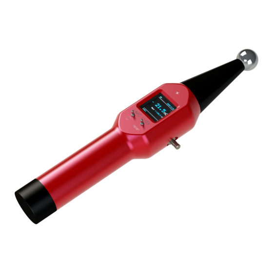
1. Product and manufacturer 1.1. Product description The coulombmeter type HMG 11/03 is used for contactless measurement of the charge transferred in a spark. It is a hand-held measuring device with color OLED display and integrated lithium-ion battery. 1.2. Type designation HMG 11/03 1.3. -
Page 4: Guide To These Operating Instructions
These operating instructions must be read, understood and observed in all points by all persons who are responsible for this device. Only with knowledge of these operating instructions can errors be avoided and safe and trouble-free operation be guaranteed. SCHNIER Elektrostatik GmbH accepts no liability for damage resulting from non-observance of these operating instructions! These operating instructions apply to: Installation and maintenance personnel (e.g. -
Page 5: Intended Use And Measuring Principle
3. Intended use and measuring principle The Coulombmeter Type HMG 11/03 is used for contactless measurement of the charge transferred in a spark. It is not suitable for measuring surface charges, which only give a measured value on contact. For a proper measurement, a spark must occur when the measuring ball approaches the test specimen. -
Page 6: Coulombmeter Circuit Principle
3.2. Coulombmeter circuit principle The charge transferred from the charged test piece via spark/brush discharge to the ball electrode is stored in capacitor C and then discharged to ground. The current, flowing across the measuring resistor, is measured. By an integral calculation, the charge is calculated from current over time. Q = I The microcontroller "MP"... -
Page 7: Functionality And Operation
4. Functionality and operation 4.1. Displays and control elements Battery charge Date indicator display Ready for measurement or actual measured value Largest measured Number of saved value measured values I-switch R-switch 4.2. Displays and Turning the coulombmeter on and off The manual coulombmeter is turned on by pushing the I-switch upwards for at least one second. -
Page 8: Display
4.3. Display Measured value OK / NOK Largest measured value (display nC Stopwatch display 4.4. Ready for measurement “Wait” signals ready for measurement. The results appear at this location after a measurement, adding the prefix. Operating manual 810461-BAL-EN-2300203 Date: 03.02.2023 8 / 24... -
Page 9: Measured Value Display After Correct Measurement
4.5. Measured value display after correct measurement Display with measured value of positive polarity (Measured value: +22,5 nC) Display with measured value of negative polarity (Measured value: -21,5 nC) Operating manual 810461-BAL-EN-2300203 Date: 03.02.2023 9 / 24... -
Page 10: Measured Value Ok / Nok
4.6. Measured value OK / NOK Depending on the success of the measurement, the following appears in the display: The measurement was successful, no measurement error was detected. The zero point could be or cannot be maintained, e.g. error due to corona charge. The measurement result is not very useful. -
Page 11: Number Of Saved Measured Values
4.7. Number of saved measured values Number of saved measured values. m:003 = 3 measured values present in memory. There are currently 3 measured values stored here. 4.8. Largest saved measured value Display of the largest saved measured value. Operating manual 810461-BAL-EN-2300203 Date: 03.02.2023 11 / 24... -
Page 12: Stopwatch Display
4.9. Stopwatch display The second counter runs since releasing the “Reset switch” and stops when a measured value is recorded (this indicator can be switched off in the settings). 4.10. Charge status The charge level for the built-in lithium-ion battery is displayed as a bar graph in the upper left corner. -
Page 13: Function Of The Buttons (Switches)
4.11. Function of the buttons (switches) R-switch (r) ↑ upward ↓ downward Only active in measurement operation! The measurements are reset and the second counter restarted in both switch directions. Upward: saves the measured value Downward: deletes the measured value. Exception: When the timer function is active, the timer can be restarted by pushing up until a valid measured value is recorded without previously having to save something. -
Page 14: Menu
Vibration (Vibration during a measurement data recording: yes/no) Date (Set date and time) When leaving the item, push upward to accept the settings Enables calibration of the device, requires consultation with SCHNIER (Item can be left by repeated “pushing down the I-switch). Operating manual 810461-BAL-EN-2300203 Date: 03.02.2023... -
Page 15: Show Memory (Call Up Menu Item 3)
5.2. Show memory (call up menu item 3) When turned on push the I-switch upward to get into the menu. Push I-switch upward until line 3 “show memory” is selected. Push I-switch down to deselect line 3 “show memory”, afterwards, the list appears with the saved measured values. 5.3. -
Page 16: Clear Memory (In Menu Item 4)
5.4. Clear memory (in menu item 4) When turned on push the I-switch upward to get to the menu. Push I-switch upward until line 4 “Clear memory” is selected. Push I-switch downward to select line 4 “Clear memory”. To delete the memory the query must be confirmed by pushing the R-switch down. (R-switch “pushed down”: delete;... -
Page 17: Show Time (In Menu Item 5)
5.5. Show time (in menu item 5) When turned on push the I-switch upward to get to the menu. Push I-switch up until line 5 “Show signal time” is selected. Push I-switch down to select line 3 “Show signal time” Using the I-switch upward with “Show signal time”,change between “Yes”... -
Page 18: Measurements With The Manual Coulombmeter
6. Measurements with the manual coulombmeter The manual coulombmeter must only be operated when grounded! The included ground connection wire must be plugged onto the POAG socket and connected with ground. The wire should hang with no loops (prevent self-induction). 6.1. -
Page 19: Exceeding The Measurement Range
6.2. Exceeding the measurement range If the following appears in the display, then the measurement range for negative charges is exceeded (blue minus sign as prefix) the measurement range for positive charges is exceeded (brown plus sign as prefix) Measured value or measurement range exceeded. The actual value exceeds the displayed value, thus the measurement must be discarded. -
Page 20: Achieving Optimum Measurement Results
6.3. Achieving optimum measurement results Electrostatic charges are generally subject to climatic influences. Therefore, measurements on charge transfer should no longer be carried out at a rel. humidity > 50 %. Because the measured values are also influenced (albeit to a lesser extent) by the abs. humidity, a higher rel. humidity can be tolerated at 10 °C, for example, than at 30 °C, for example. -
Page 21: Functional Test (Replacement For Battery Test)
If the lithium-ion battery is charged at least every 6 months, it is ensured that the integrated real-time clock remains buffered for approx. 12 months without using the device. The USB-C charging port is protected behind the black cover at the end of the Coulombmeter. Screw cap to the USB-C charging port... -
Page 22: Maintenance Of The Handheld Coulombmeter
7. Maintenance of the handheld coulombmeter Avoid storage and keeping at temperatures < +5 °C. Avoid soiling the surface. Clean with a dry textile cloth. Remove stubborn dirt from the ball electrode and the insulating cone with isopropanol and a textile cloth. (Caution: highly flammable!) ... - Page 23 8. Accessories HV generator, type HER 26/01 Suitable for charging insulating surfaces. Output voltage: max. 70 kV Output current: max. 65 µA Output power: max. 0,6 W Fakir electrode type HMG 13/01 96 pins on 100 cm For defined charging of surfaces in combination with the HV generator Type HER 26/01 Operating manual 810461-BAL-EN-2300203...
-
Page 24: Ec Declaration Of Conformity
The CE labelling has been carried out according to the following directive: 2014/30/EU Note: The device is suitable for measurements according to the following standards: EN 60079-0 (VDE 0170-1) Reutlingen, February 03 2023 SCHNIER Elektrostatik GmbH Olav Schnier Geschäftsführer General Manager Operating manual 810461-BAL-EN-2300203 Date: 03.02.2023...
Need help?
Do you have a question about the HMG 11/03 and is the answer not in the manual?
Questions and answers