Advertisement
Quick Links
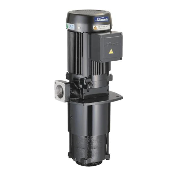
クーラントポンプ RCD形
このたびは、ダーティタイプクーラントポンプをお買上げい
ただきましてまことにありがとうございます。
ご使用前に取扱説明書を必ずお読みになり、正しく安全にお
使いください。取扱説明書には危害や損害を未然に防止するた
めの注意事項が記載されております。
また、お読みになった後は、お使いになる方がいつでも見ら
れるところに必ず保管してください。
1 はじめにご確認ください ・・ 2
2 仕 様 ・・・・・・・・・ 2
3 製品の構成 ・・・・・・・・ 5
4 据 付 ・・・・・・・・・ 7
5 配 管 ・・・・・・・・・ 9
特に注意していただきたいこと
1.修理技術者以外の人は、分解したり修理や改造を行わないでください。
修理に不備があると、感電や火災、液漏れなどの原因になります。
2.点検・交換の際は、必ず電源を遮断して作業を実施してください。漏電・感電やけ
がの恐れがあります。
3.接地工事は通電前に必ず行ってください。アース線を確実に取り付けないで運転す
ると故障、漏電・感電・火災の原因になります。
適用範囲外での使用、注意書きなどの不遵守、不当な修理・改造、天災地変に起因するも
の、設置環境(電源異常・異物など)によるもの、法令・省令またはそれに準じる基準など
に不適合のもの、不慮・故意による故障・損傷のもの、消耗部品の交換、転売による不具合
などは保証対象外となる場合があります。
また注意事項は、危害や損害の大きさと切迫の程度を明示するために、誤った取扱いをす
ると生じることが想定される内容を、「危険」「警告」「注意」の3つに区分しています。
いずれも安全に関する重要な内容ですので、必ず守ってください。
:人が死亡または重傷を負う危険が差し迫って生じると想定される内容。
危険
:人が死亡または重傷を負う可能性が想定される内容。
警告
:人が傷害を負う可能性および物的損害のみの発生が想定される内容。
注意
取扱説明書
< 目 次 >
6 電気工事 ・・・・・・・・・・ 9
7 運 転 ・・・・・・・・・ 11
8 保守・点検 ・・・・・・・・ 12
9 故障の原因と対策 ・・・・・ 14
10 廃 棄 ・・・・・・・・・ 15
1
8 7 4000 1 1
Advertisement

Related Manuals for Kawamoto Pump RCD-40A0.75


Summary of Contents for Kawamoto Pump RCD-40A0.75
- Page 1 8 7 4000 1 1 クーラントポンプ RCD形 取扱説明書 このたびは、ダーティタイプクーラントポンプをお買上げい ただきましてまことにありがとうございます。 ご使用前に取扱説明書を必ずお読みになり、正しく安全にお 使いください。取扱説明書には危害や損害を未然に防止するた めの注意事項が記載されております。 また、お読みになった後は、お使いになる方がいつでも見ら れるところに必ず保管してください。 < 目 次 > 1 はじめにご確認ください ・・ 2 6 電気工事 ・・・・・・・・・・ 9 2 仕 様 ・・・・・・・・・ 2 7 運 転 ・・・・・・・・・ 11 3 製品の構成 ・・・・・・・・ 5 8 保守・点検 ・・・・・・・・ 12 4 据 付 ・・・・・・・・・ 7 9 故障の原因と対策 ・・・・・ 14 5 配 管 ・・・・・・・・・ 9 10 廃 棄 ・・・・・・・・・ 15 特に注意していただきたいこと 1.修理技術者以外の人は、分解したり修理や改造を行わないでください。 修理に不備があると、感電や火災、液漏れなどの原因になります。 2.点検・交換の際は、必ず電源を遮断して作業を実施してください。漏電・感電やけ がの恐れがあります。 3.接地工事は通電前に必ず行ってください。アース線を確実に取り付けないで運転す ると故障、漏電・感電・火災の原因になります。 適用範囲外での使用、注意書きなどの不遵守、不当な修理・改造、天災地変に起因するも の、設置環境(電源異常・異物など)によるもの、法令・省令またはそれに準じる基準など に不適合のもの、不慮・故意による故障・損傷のもの、消耗部品の交換、転売による不具合 などは保証対象外となる場合があります。 また注意事項は、危害や損害の大きさと切迫の程度を明示するために、誤った取扱いをす ると生じることが想定される内容を、「危険」「警告」「注意」の3つに区分しています。 いずれも安全に関する重要な内容ですので、必ず守ってください。 :人が死亡または重傷を負う危険が差し迫って生じると想定される内容。 危険...
- Page 2 1 はじめにご確認ください 製品がお手元に届きましたら、下記項目を調べ、不具合な点がございましたら、お手数でもご購入先へ ご連絡ください。 ・ 天地を確認の上、注意して開梱してください。けがをする恐れがあります。 ・ 包装用のバンドがある場合、バンドを持って荷扱いしないでください。バンドが切れけがをする 恐れがあります。 ・ この商品は重心が偏っています。不用意に持ち上げると腰を痛めることがあります。 ・ ご注文通りの製品か、銘板を見てご確認ください。 (形式、定格出力、定格電圧、周波数、全揚程 など) ・ 輸送中に破損した箇所や、ボルト、ナットなどのゆるみはないか、ご確認ください。 ・ ご注文の製品の付属品が全て入っているか、ご確認ください。 ・ 弊社にお問い合わせの際は、『形式』及び『製造番号』をご連絡ください。 2 仕 様 危 険 最高仕様圧力以上では絶対に使用しないでください。重大事故につながる恐れがあります。 ● 注 意 決められた製品仕様以外では使用しないでください。感電や火災、液漏れなどの原因にな ● ります。 循環用途に使用し、発錆や金属の腐食・溶出を許容できない場合は注意が必要です。 ● ポンプや設備全体を含め選定・検討してください。 用途に合った商品をお選びください。不適切な用途で使うと事故の原因になります。 ● 危険・警告・注意ラベル類には人身への危害または財産への損害を引き起こす可能性のあ ● る事項が記載してありますので必ず遵守ください。 守らないと機器が故障したり感電、火災、けがなどの原因になります。 仕様液質として記載のない液体などには使用しないでください。ポンプが故障し、漏電・ ● 感電・火災の原因になります。...
- Page 3 2.1 全機種共通 クーラント液、 切削液 (注) 清水, 海水, 酸性液, 有機溶剤などには、 ご使用になれません。 また、 油性液の場合、 粘度が高すぎるとモータが過負荷になり焼損の恐れがあります。 液質 必ず下表に示します粘度限界以下のものをご使用ください。 使用液 なお、 粘度は液温が下がると大幅に高くなることがありますので、 ご使用に際しては 最低液温時の粘度をご確認ください。 液温 0〜40℃ 使用粘度限界 75 ㎜ 2 / (但し、 RCD−40HA (B)3.0(T4)形は60㎜ 2 / ) s s 屋内 標高1000m以下 爆発性ガス、 蒸気のある場所は使用不可 設置場所 周囲温度 0〜40℃ 湿度 85%RH以下 (結露なきこと) 設置条件...
- Page 4 高揚程タイプ 形式 RCD−40HA (B) 3.0 RCD−40HA (B) 3.0T4 公称出力[kW] 3.0 3.0 周波数[Hz] ※1 50 60 50 60 200 400 380 定格電圧[V] ※2 200 220 440 400 230 460 15.2 7.6 5.4 定格電流[A] 11 14 7 5.5 14 7 吐出し量[L/min] 300...
- Page 5 3 製品の構成 本図は、RCD形の代表機種を示します。機種 3.1 構造図RCD−40A (E) 1.5 (T4) によっては図と多少異なるものもあります。 1 N o. 名 称 材 料 2 1 ファンカバー SPCC 3 2 ファン PA 3 オイルシール NBR 4 4 波形座金 SK−85M 5 玉軸受 − 5 6 6 端子ねじ(M4) SWRM 7 7 アースねじ(M4) C2700 8 8...
- Page 6 3.2 構造図RCD−40B(E) 3.0 (T4) 本図は、RCD形の代表機種を示します。機種 1 によっては図と多少異なるものもあります。 2 N o. 名 称 材 料 3 1 ファンカバー SPCC 4 ファン PA 2 5 3 オイルシール NBR 6 4 波形座金 SK−85M 5 玉軸受 − 7 6 端子ねじ(M4) SWRM 8 3 1 7 アースねじ(M4) C2700 9...
- Page 7 4 据 付 警 告 荷下ろし、搬入、据付で本製品を吊り下げる場合は、カタログ、外形寸法図、取扱説明書 ● などに従って製品の質量や吊り方を確認し、正しく行ってください。また、吊り具の定格 荷重以上の製品は吊らないでください。吊り下げが不完全な場合、落下によるけがの原因 になります。 据付は本書に従って確実に行ってください。据付が不完全な場合、感電や火災、落下によ ● るけがの原因になります。 爆発性雰囲気中では使用しないでください。火災の恐れがあります。 ● 適用される法規定(電気設備技術基準・内線規程など)に従って施工してください。法規 ● 定に反するだけでなく感電・火災・落下・転倒によるけがなどの原因になります。 機器の寿命を考慮し、設置は風通しがよく、ほこり、腐食性及び爆発性ガス、塩分、湿気、 ● 蒸気、結露などがなく、風雨、直射日光の当たらない所を選んでください。 悪環境下では、モータ・制御盤の絶縁低下などにより、漏電・感電・火災の原因になりま す。 注 意 機械および化学工場など酸・アルカリ・有機溶剤・塗料などの有害ガス、腐食性成分を含 ● んだガスが発生する場所または埃の多い場所には設置しないでください。漏電や火災の原 因になることがあります。 排液処理、防液処理されていない場所には設置しないでください。液漏れが起きた場合、 ● 大きな被害につながる恐れがあります。※排液処理、防液処理されていない場合の被害に ついては責任を負いかねます。 開口部(ファンカバー、吐出し口、吸込口など)に異物や指を入れないでください。けが ● や破損の恐れがあります。 周囲にモータ冷却の通風を妨げるような障害物がある場所に据付ないでください。破損、 ● 焼損や火災の原因になります。 配管のねじ部にはシール剤を使用して、確実に締めてください。液漏れの原因になります。 ● 機器に衝撃を与えたり、転倒させないでください。破損する恐れがあります。 ● 据付、点検などの作業を行う前に、周辺を整理してください。滑ったり、つまずいたりし ●...
- Page 8 4.1 据付 1.据付には以下の場所をお選びください。 ・凹凸のない水平で丈夫な場所(外部からの振動加速度が約6.9m/s 以下の場所) ・風通しがよく、モータへ使用液や直射日光の当たらない場所 ・モータの周囲温度が40℃を超えない場所 ・保守・点検に便利な場所(狭い場所は避けてください。 ) ・製品の銘板が良く読める場所(銘板は取り外さないでください。 ) 2.ポンプを吊り下げて運ぶ場合は、本体の両側面にあるアイボルトに吊り具等を取り付けて運んで ください。 3.ポンプはタンク底面より15 以上高くして設置してください。切削粉などの沈殿物によるスト mm レーナの目詰まりを防ぐため、タンク底面からできるだけ高く設置することをお勧めします。 4.タンクはできるだけ大きな容量のものをご使用ください。タンク容量はポンプ吐出し量(毎分当 り)の3倍以上をお勧めします。タンク容量が小さいと、液温が上昇する、ストレーナの目詰ま りが早くなる、気泡を吸込み吐出し量が減少するなどの原因になります。 5.タンクへの取付は、ポンプのフランジにある取付穴で確実に固定してください。取付穴は2×2 ヶ所ありますが、使用範囲を拡大するためのものであり、実際の取付は対角方向の2ヶ所で固定 してください。 取付穴はキャップをしていますので、使用する2ヶ所のキャップのみを取り外してください。 残る2ヶ所はキャップを取り外さずそのままご使用してください。 6.運転水位は下記の通りです。 ・最高液面位 液面がこの位置より高くなるとモータ内部に液が浸入する恐れがあるため、表示した値 より低い位置にしてください。 ・最低液面位 液面がこの位置より低くなると空気を吸込み吐出し量の減少や揚水不能になるため、表 示した値より高い位置にしてください。空運転(ポンプに水のない状態での運転)防止 のため、できるだけ高い位置にしてください。 最高液面位 最低液面位 形 式 A [㎜] B[㎜] RCD−40A (E) 0.75 (T4) 20...
- Page 9 7.端子箱の位置変更は特殊仕様となります。 VC81 現地で変更が必要な場合は専門業者へ依頼してく 12時 ださい。 端子箱の位置は、モータフレームを組み替えるこ とで9 0°毎に位置を変更できます。(右図参照) VC80 VC82 5 配 管 9時 3時 吐出し 5.1 配管 1.配管の荷重が直接ポンプにかからないように配管 端子箱 支えを設置してください。 基本機種 6時 2.配管は下記のようにしてください。 ・できるだけ短く、太くする ・エルボ等の曲がりやチーズ等の分岐を少な くする ・バルブ類などの障害物を少なくする (注)配管が長かったり細かったり曲がりや障害物が多かったりすると、吐出し量が少なくなり ます。 3.配管の接続部(ねじ込み部)は漏水しないようにシールテープや液体パッキンなどで確実にシー ルしてください。但し、ポンプ吐出し口は、配管を無理にねじ込まないでください。吐出し口が 破損する原因になります。 管用ねじの締付けトルクは下表を参考にしてください。 管用ねじの呼び (参考)締付けトルク Rp 1 1 / 2 180[N ・ m] 4.ソレノイドバルブ...
- Page 10 注 意 端子箱の電源ケーブル引出口から端子箱内に切削粉や使用液などが浸入しないように、防 ● 塵、防滴処理を施してください。感電や火災の原因になります。 結線は、本書や端子箱内の結線図に従って施工してください。配線を誤ると感電や火災な ● どの原因になります。 電源ケーブルや制御線を同一管内またはダクト内に併設させないでください。本製品や他 ● の機器が誤動作する恐れがあります。 6.1 端子の接続は端子記号に従って電源へ確実に接続してください。 モータの端子数は3本(U、V、W)です。 3本リード:直入始動 端子ねじの呼び (参考)締付けトルク 電 源 R S T M4 1.3[N ・ m] モータ U V W 6.2 接地端子はモータの端子箱内に マークで表示していますので、必ず接地工事を行ってください。 アースねじの呼び (参考)締付けトルク 接地工事の種類 M4 1.3[N ・ m] 定格電圧 200 D種接地工事 [V] アース線の色:グリーンイエロー 400 C種接地工事 6.3 配線の太さは下表を参考にしてください。 配線の銅線太さ(参考) 定格電圧 公称出力 配線の最小銅線太さ...
- Page 11 7 運 転 警 告 配線を取り付けたり取り外したりする場合、必ず電源を遮断して電気がきていないことを ● 確認してください。感電する恐れがあります。 モータには水をかけないでください。感電・漏電・火災や故障の原因になります。 ● 運転中は吸込口に手足等を近づけないでください。吸い込まれてけがをする恐れがありま ● す。 製品を吊上げ状態での使用及び作業は行わないでください。落下及びけがの恐れがありま ● す。 カバー(軸ガード)を外したまま運転しないでください。回転部に巻き込まれたり物が接 ● 触し飛散するなどしてけがの原因になります。 電源を投入後及び通電状態にて制御盤の充電部やモータ端子、ケーブル先端部などに触れ ● ないでください。漏電・感電・火災の原因になります。 停電の場合は電源スイッチを切ってください。復電時に製品及び設備機器の破損や急にポ ● ンプが運転してけがをする恐れがあります。 注 意 定格電圧以外では使用しないでください。火災や感電の原因になることがあります。 ● 運転中は回転部分に触れたり、モータの開口部に指や棒などを入れないでください。感電 ● やけがの原因になります。 長期間ご使用にならない場合は電源を遮断してください。絶縁劣化による感電や漏電、火 ● 災の原因になります。 インバータで駆動する場合は、周波数60Hzを超えて運転しないでください。焼損や火 ● 災の原因になります。また、400V級インバータで駆動する場合は、インバータ側に抑 制フィルタやリアクトルを設置してください。絶縁破壊による火災、破損の原因になりま す。 使用液は使用液粘度限界より高粘度のものを使用しないでください。焼損や火災の原因に ● なります。 長期保管後や休止後の運転開始時には、「据付」「運転」の順に従い、試運転を実施して ●...
- Page 12 7.1 試運転 1.漏電しゃ断器の容量および電源電圧が正しく、配線が正しく行われているかご確認ください。 2.タンクに運転水位まで使用液を入れてください。(4. 1の6 参照) 3.電源を入れ、ポンプの回転方向がファンカバーの矢印方向と一致するかご確認ください。逆回転 の場合は、電源を切って、電源ケーブル3本の内2本を入れ替えてください。 4.配管(ノズル)から使用液が出ることをご確認ください。また、圧力、電流、振動、騒音等の異 常がないことをご確認ください。 5.圧力計・連成計等のコックは、測定時以外は閉じておいてください。開けておくと故障しやすく なります。 6.メカニカルシール・レス(軸貫通部の密封装置なし)構造になっているため、ポンプのカバーと 中間ケーシングの間から液が出ますが製品の異常ではありません。 7.2 運転 1.吐出し配管にバルブを設置すれば、バルブの開閉による流量調整が自由に行えます。バルブを締 め切ってもモータは過負荷運転になりません。 2.インバータによる可変速運転でも、流量調整が自由に行えます。周波数5〜60Hz、定格電流 値以下で運転してください。但し、インバータのお取扱いについては、インバータメーカーに従 ってください。インバータの種類や設定によっては、モータが焼損する恐れがあります。インバ ータで運転する場合は、ご使用になられるインバータとポンプの適合試験を行うことをお勧めし ます。 3.始動・停止頻度は、最大100回/時を目安に行ってください。高頻度の運転は、モータの絶縁 劣化などの電気部品の故障の原因になります。 8 保守・点検 警 告 修理技術者以外の人は、分解したり修理や改造を行わないでください。修理に不備がある ● と、感電や火災、液漏れなどの原因になります。 修理の際は当社純正部品を使用ください。純正部品以外を使用された場合、故障及び事故 ● の原因になります。また、正常な機能を発揮できない恐れがあります。 動かなくなったり異常(ケーブル破れ、コゲ臭いなど)がある場合、直ちに運転を停止し ● て電源を遮断し、ご購入先もしくは最寄りの弊社営業所に点検あるいは修理を依頼してく ださい。異常のまま運転を続けたり、修理に不備があると、漏電・感電・火災、液漏れな どの原因になります。 点検・交換の際は、必ず電源を遮断して作業を実施してください。漏電・感電やけがの恐 ● れがあります。 モータの絶縁抵抗値が1MΩ以下に低下した場合、すぐにご購入先もしくは最寄りの弊社 ● 営業所に連絡してください。モータが焼損したり、感電や火災を起こす恐れがあります。...
- Page 13 注 意 長期間安心して使用頂くために定期点検と日常点検両方の実施をお勧めいたします。点検 ● を怠ると、ポンプの故障、事故などの原因になります。定期点検についてはご購入先、も しくは最寄りの弊社営業所にご相談ください。 消耗品は定期的に交換を行ってください。劣化・摩耗したまま使用になると、液漏れや焼 ● 付き・破損などの事故の原因になります。定期点検、部品交換などは、ご購入先もしくは 最寄りの弊社営業所に依頼してください。 点検は点検項目に従って必ずおこなってください。故障を未然に防止できず、事故につな ● がる恐れがあります。 分解・点検時には内部の圧力がゼロであることを確認してください。液が噴き出し事故や ● けがをする恐れがあります。 長期保管後や休止後の運転開始時には、「据付」「運転」の順に従い、試運転を実施して ● ください。固着などによるポンプ拘束、モータ焼損などの恐れがあります。 定期的に保護継電器の動作確認を行ってください。事故時に正常動作せず、感電や故障の ● 恐れがあります。 下記点検項目を随時点検し、必要に応じてお手入れおよび消耗部品の交換を行ってください。 8.1 日常点検 確認事項 判 定 基 準 電流 銘板電流値以下 電圧 定格電圧の±10%以内 騒音・振動 初期より変化のないこと モータの絶縁抵抗 1MΩ以上あること ポンプのストレーナが目詰まりをおこしていないこと タンク内 ※目詰まりをおこしている場合は清掃してください 異常を早く発見するには、 日々の変化を知ることが大切です。そのためにも運転日誌を付けられることを お勧めします。 8.2 定期点検 確認事項...
- Page 14 9 故障の原因と対策 警 告 動かなくなったり異常(ケーブル破れ、コゲ臭いなど)がある場合、直ちに運転を停止し ● て電源を遮断し、ご購入先もしくは最寄りの弊社営業所に点検あるいは修理を依頼してく ださい。異常のまま運転を続けたり、修理に不備があると、漏電・感電・火災、液漏れな どの原因になります。 点検・交換の際は、必ず電源を遮断して作業を実施してください。漏電・感電やけがの恐 ● れがあります。 下表の点検項目を実施いただいた後でも異常がある場合は、ご購入先もしくは最寄りの弊社営業所に ご連絡ください。 参照 現 象 原 因 対 処 方 法 ページ 故障原因を取り除き、再度電源を 漏電しゃ断器の電源が切れて − いる 投入する ポンプが運転しない 電源関係に異常がある 点検・修理する − 正しく結線する 単相結線になっている 1 0 結線を正しくする ポンプの回転方向が逆 1 0、 1 1、 1 2 インペラに異物が詰まっている 専門業者に点検・修理を依頼する −...
- Page 15 1 0 廃 棄 注 意 ポンプや部品を廃却する場合は、その国(地域)の法律に従って処理してください。 ●...
-
Page 16: Table Of Contents
8 7 4000 1 1 Coolant Pump RCD Type Instruction Manual Thank you for purchasing the dirty type coolant pump RCD. This instruction manual provides information for the customer to safely use this pump unit. Always read this manual thoroughly and fully comprehend the contents before starting work. Please keep this instruction manual in a handy place for quick reference < Contents > 1 Introduction ・ ・ ・・・・17 6 Electrical Work ・・・・・・・・・24 2 Specifications ・ ・ ・ ・・・17 7 Operation ・・・・・・・・・・・ 25 3 Configuration ・ ・ ・・・・20 8... - Page 17 1 Introduction Please check the following items upon receipt of the product. If there are any problems, contact your dealer. ・ Confirm the upside of the package and open the package carefully. Failure to do may result in injuries. ・ Do not load handing with the band. There is a possibility that it may be injured by the band off. ・ This product is skewed center of gravity. Lifted carelessly may occur to be low back pain. ・ Check the nameplate to ensure that the correct pump has been delivered. Check the type, output, voltage, frequency, etc. of the delivered pump in reference with the name plate to verify that the correct product has been delivered. ・ Check that no parts have been damaged during transportation, and that none of the bolts, nuts, etc., are loose. Tighten any part that is loose. ・ Check that all ordered accessories have been delivered. 2 Specifications Caution Always use this pump within the specified product specifications. ● Failure to do so could result in electric shocks, fires, water leaks, etc. Never use this product above the maximum working pressure. There is a risk of ● serious accidents. Caution is required when using this product in a circulatory application, in which ● there is no tolerance for rusting, metal corrosion or elution. Carefully select and review the pump and entire system. The circulating water could become concentrated and lead to unforeseen damage. Select a product that matches the application. Using a product for an inappropriate ● application will cause faults. The Danger, Warning and Caution labels indicate information on matters that could ● cause bodily harm or property damage. Always observe the indicated information. Failure to do so could result in device damage, electric shock, fire or injury, etc. 2.1 All the model community Coolant, Cutting oil ※The pump cannot be used with fresh water, ocean water, organic solvent, acid liquid. Contents Also, using high viscosity fluids will shorten the life of the motor and may cause ...
- Page 18 2.2 Table 200V Type Type RCD-40A0.75 RCD-40A(B)1.5 RCD-40A(B)2.2 RCD-40A(B)3.0 Output [kW] 0.75 Frequency [Hz] ※1 Rated voltage[V] ※2 Rated current [A] 11.5 11.5 Quantity [L/min] Total head [m] 23.5 Mass [kg] 31(36) 39(44) 43(47) 400V Type Type RCD-40A0.75T4 RCD-40A(B)1.5T4 RCD-40A(B)2.2T4 RCD-40A(B)3.0T4 Output [kW] 0.75 Frequency [Hz] ※1 Rated voltage[V] ※2 Rated current [A] Quantity [L/min] Total head [m] 23.5 Mass [kg] 31(36) 39(44) 43(47) High Pressure Type Type RCD-40HA(B)3.0...
- Page 19 【Puremium Efficiency (IE3) Motor】 200V Type Type RCD-40AE0.75 RCD-40A(B)E1.5 RCD-40A(B)E2.2 RCD-40A(B)E3.0 Output [kW] 0.75 Frequency [Hz] ※1 Rated voltage[V] ※2 Rated current [A] 11.5 14.5 Quantity [L/min] Total head [m] 23.5 Mass [kg] 33(38) 40(45) 48(52) 400V Type Type RCD-40AE0.75T4 RCD-40A(B)E1.5T4 RCD-40A(B)E2.2T4 RCD-40A(B)E3.0T4 Output [kW] 0.75 Frequency [Hz] ※1 Rated voltage[V] ※2 Rated current [A] Quantity [L/min] Total head [m] 23.5 Mass [kg] 33(38) 40(45) 48(52) ※1:Within -5〜+3% rated frequency at motor. ※2: Within ±10% rated voltage at motor.
- Page 20 3 Configuration This figure shows the representation model 3.1 RCD−40A(E) 1.5 (T4) of RCD. The actual model may differ slightly from this figure. 1 N o. Name Material 2 1 Fan cover SPCC 3 2 External fan 3 Oil sesl 4 4 Wave washer SK-85M 5 Ball bearing − 5 6 6 Terminal screw(M4) SWRM 7 7 Earth screw(M4) C2700 8 Ball bearing − 8...
- Page 21 3.2 RCD−40 B(E) 3 . 0(T4) This figure shows the representation model of RCD. The actual model may differ slightly 1 from this figure. 2 N o. Name Material 3 1 Fan cover SPCC 4 2 External fan 5 3 Oil seal 6 4 Wave washer SK-85M 5 Ball bearing − 7 Terminal screw(M4) SWRM 6 8 7 Earth screw(M4) C2700 9 8...
-
Page 22: 4 Installation
4 Installation Warning Before hoisting the pump unit during unloading, loading, and installation, check the ● product catalog, the installation drawing, and the instruction manual, etc., to verify the pump unit weight and the hoist method. Do not attempt to hoist a pump unit that exceeds the hoist s rated load. Incorrect hoisting can result in drops and injuries. Securely install the pump as explained in the instruction manual. Incomplete ● installation could result in electric shock, fires or injury from dropping. Do not use the pump in flammable gas, Incorrect using could result in fire. ● Install the product according to applicable laws and regulations (Electrical ● Installation Technical Standards, Wiring Regulations). Failure to do so is not only illegal, it may result in electric shock, fire, or injury from dropping or falling, etc. In consideration of the product life, select a well-ventilated place, that is free of dust, ● corrosive and explosive gas, salt, humidity, steam and dew condensation, and is not subject to wind, rain or direct sunlight. The motor or control panel insulation could drop in a poor environment and lead to residual current, electric shock or fires. Caution Do not install this pump in places such as machine and chemical factories where ● toxic gases including acid, alkaline, organic solvents or paint are present, where gases containing corrosive elements are generated, or where there are high levels of dust. Failure to observe this could result in earth leakage or fires. Do not install this pump in a place that has not been treated for drainage or ● waterproofing. Major disasters could occur if water leaks. Do not insert foreign objects or fingers etc. into openings (fan cover, discharge port, ● suction port, etc.) of the pump. Incorrect doing could result in electric shock, injuries and damage to equipments. Do not install in a place as in the obstruction are around the pump to block ● ventilation for cooling motor effect. Incorrect doing could result in burns, fires etc. Do not stand on the pump. Failure to observe this could result in injuries and ... -
Page 23: 5 Piping ・ ・・・・・23
4.The tank should use as big capacity as possible. The recommended tank capacity is at least three times of discharge amount per minute. Using a tank with excessively small capacity may cause problems, such as the fluid temperature increasing, the strainer clogging with cutting chips faster than usual, reduction in the amount of discharge due to generation of bubbles, etc. 5.Attach to a tank, certainly fix to the hole of attachment in the flange of a pump. Although there are 2x2 attachment holes, it is for expanding the use range and please fix actual attachment at two places of the direction of a diagonal. Since the attachment hole is capping, please remove only two caps to be used. Two places which remain should not remove a cap but should use it as it is. 6.The operating liquid level is as follows. ・Highest liquid level For safety, keep the fluid level as low as possible. ・Lowest liquid level For safety, keep the fluid level as high as possible. Highest liquid Lowest liquid Type level A[mm] level B[mm] RCD-40A(E)0.75(T4) RCD-40A(E)1.5(T4) RCD-40B(E)1.5(T4) RCD-40A(E)2.2(T4) Highest Liquid RCD-40(E)B2.2(T4) Level RCD-40(H)A(E)3.0(T4) RCD-40(H)B(E)3.0(T4) ※Please put in calmly and not to involve in air, Lowest When putting use liquid into a tank. Liquid Level 7.Position change of a terminal box serves as special specification. VC81 Depend on specialist on the site when a change is 12:00 necessary. - Page 24 6 Electrical Work Warning The electrical work must be completed according to the Electrical Installation ● Technical Standards Wiring Regulations and any other applicable regulations. Improper wiring and connections could lead to earth leakages or fires. Securely earth the equipment , and install a dedicated residual current circuit ● breaker on the power supply side. Failure to observe this could result in earth leakages, electric shocks or fires. After work, return the terminal box cover to original position. Failure to observe ● this could result in electric shocks or fires. Always earth the pump before turning the power on. Do not connect the earthing ● wire to gas pipes, water pipes, lightning rods or telephone earthing wires. Failure to earth the equipment correctly could result in electric shocks. Confirm whether a wiring joint, a connection department become loose or separate. ● Only one place loosens or separated could result in fires or electric shock. Clean off any dust from the power plug, wiring connectors, connections and ● terminals. An electrical discharge on dust could cause heating or a fire. Caution Do not damage, modify, forcibly bend, pull, twist or bundle the power cable. Do not ● place heavy items on, catch or modify the cable. Failure to observe this could lead to power cable damages, electric shocks or fires. Take sufficient precautions to prevent chips, coolant, etc. from entering the ● terminal box through the lead-in port. Failure to observe this could result in electric shocks or fires. Refer to the connection diagram inside the terminal box or this instruction manual ● for power cable connection. Incorrect wiring could result in electric shock or fire. 6.1 For standard voltage products, see the drawing on the below and connect the motor terminals to the power supply terminals correctly. (The number of motor terminals is three.) Direct on line starting Power supply terminals ...
-
Page 25: Operation
7 Operation Warning Always turn OFF the power and ensure that no power is being supplied to the ● pump when attaching or disconnecting wiring. Failure to observe this could result in electric shocks. Do not pour water into the motor. Failure to observe this could result in electric ● shocks, short circuit, fires, and malfunction. Always turn the power switch OFF under a power failure. when a power supply ● returns, suddenly operation could in injuries. Do not bring hands and feet close to a suction port during operation. Failure to ● observe this could result in injuries by being inhaled. Do not use or perform work while the product is suspended. There is risk of ● dropping and injury. Do not start operation with the shaft joint guard removed. Objects could get caught ● in or contact the rotating section and fly around and cause injury. Caution Do not use this product out of the rated voltage. Failure to observe this could result ● in fires or electric shocks. Do not touch the rotating area during operation, and do not insert fingers or rods, ● etc. into the motor openings. Failure to observe this could result in electric shocks and injuries. Do not touch pump or motor during operation . The motor could reach high ● temperature and lead to burns. Turn OFF the power when not using the pump for long periods of time. Failure to ● observe this could result in earth leakages, electric shocks, or fire due to deterioration of the insulation. Do not use the product over the frequency 60Hz (50Hz only model is 50Hz) when ● driven with an inverter. Failure to observe this could result in the pump burning out or fires. When operating the motor with a 400V class inverter, install a suppressing filter or ... -
Page 26: Maintenance & Inspection
5 . The pressure gauge and compound gauge s cocks should be closed except measurement. Leaving these cocks open will increase the risk of damage. 6 . It is not unusual although liquid comes out from between the cover and stage casings for the structure where the mechanical seal is not used. 7.2 Operation 1.Install valve in the discharge pipe, flow adjustment is possible by opening and closing of a valve. A motor does not become overload operation even if it closes a valve. 2.Flow adjustment is possible at good operation in variable speed by an inverter. When you use an inverter, please operate with the frequency of 5 〜 60 Hz, and below an amperage rating value. However, as for an inverter, directions for use should follow an inverter maker's directions. There is a possibility that a motor may be damaged by fire depending on the kind of inverter or a setup. We recommend to do the conformity examination of an inverter and a pump. 3.The frequency of start and stop makes max100 time an aim every hour . Operation of high frequency causes failure of electric parts, such as insulated degradation of a motor. 8 Maintenance and Inspection Warning If the pump does not operate or if an abnormality is sensed (such as burning smell) , ● stop operation immediately and turn OFF the main power. Then, contact the place of purchase or a designated service center for inspections and repairs. Failure to observe this could result in electric shocks, fires, water leaks, etc. The product must never be disassembled, repaired or modified by any person other ● than a qualified repair technician. Improper repairs could lead to electric shocks, fires or water leaks. Always turn OFF the power and ensure that no power is being supplied to the ● pump before starting maintenance servicing. Failure to observe this could result in ... -
Page 27: Trouble Shooting
Confirm the following check item at any time, and change care and the consumption part as needed. 8.1 Daily inspection, Check item Failure criterion Current Below the current value of a name plate. Voltage Less than ±10% of rated voltage. Noise value/Vibration Are changeless from the first stage. There is no clogged in the strainer of a pump. Inside of a tank ※Please clean, when there is a jam. In order to discover abnormalities early, it is important to get to know a daily change. We recommend to keep journal operation diary for that purpose. 8.2 Periodic inspection Check item Contents Motor surface Dust, oil, etc. adhering to the surface are cleaned. Inside of a tank Remove chip precipitating in a tank base . Insulation resistance More than 1MΩ. Be careful when using solvent or similar to clean the pump. Inappropriate use of solvent may result in poisoning. In addition, the use of thinner and/or benzine may cause a change or abruption of painting color of the pump. 8.3 Consumable parts The following parts are consumable parts. Refer to the replacement guidelines and replace the parts. Part name Replacement frequency The state of frequency When generation of heat, noise, Bearing About 2 years and unusual vibration occur. Bush − When worn out. - Page 28 Refer Problem Cause Countermeasure page Pump rotation direction is 24,25 Correct the wiring. reversed. Impeller is clogged with foreign Have specialist repair. − matter. The strainer is clogged with − Have specialist repair. Pump rotates, but no foreign objects. water is discharged. The pipe is clogged. Inspect and repair. − − Prescribed discharge Worm parts. Have specialist repair. amount/pressure is A pump is suspended and it is not obtained Air has collected in the pump. started again. Air is extracted from − an air bleed valve. Large amount of bubbles in fluid. Prevent bubble generation/suction. − An operating fluid level is as lower Adjust fluid level. as the lowest fluid level. Piping loss is high. Review piping.
Need help?
Do you have a question about the RCD-40A0.75 and is the answer not in the manual?
Questions and answers