Table of Contents
Advertisement
Quick Links
Advertisement
Table of Contents

Related Manuals for ASTRO AOTDR


Summary of Contents for ASTRO AOTDR
- Page 1 DRAFT VERSION Version 04-2021A...
-
Page 2: Table Of Contents
Description of performance..........page 11 Warranty conditions.............page 12 Disposal................page 12 Device description...............page 13 Preparation.................page 18 Introduction to measuring with the AOTDR......page 20 Setting measurement conditions.........page 26 DRAFT VERSION Making measurements............page 31 Expanding the waveform and moving the display area..page 39 File operation..............page 47 Entering characters.............page 50... -
Page 3: Before Starting Operation Of The Device
A PDF version of this manual is available to download on the ASTRO website (there may be a more recent version). The ASTRO company confirms that the information in this... -
Page 4: Symbols And Conventions Used
Used batteries must be disposed of at approved recycling points. Batteries must be completely discharged before being disposed. This symbol indicates components which must not be disposed of with household rubbish being disposed of. page 4 Operating manual AOTDR - Version 04-2021A... -
Page 5: Proper Use
Target group of this manual The target group for installation and starting operation of the ASTRO optical transmission technology are qualified experts who have training enabling them to perform the work required in accor- dance with EN 60728-11 and EN 62368-1. Unqualified persons are not allowed to install and start operation of the device. -
Page 6: Important Safety Information
A PDF version of this manual is available to download on the ASTRO website (there may be a DRAFT VERSION more recent version). - Page 7 Verify that the product is set to match the available line voltage, the correct fuse is installed, and all safety precautions are taken Operating manual AOTDR - Version 04-2021A page 7...
- Page 8 Such abnormally high voltage or frequency from a gene- rator may cause fuming, electric shock or equipment damage and may result in personal injury, death or fire. Make sure the generator is regularly checked and serviced. page 8 Operating manual AOTDR - Version 04-2021A...
- Page 9 Possible equipment failure may result. Operating personnel is not allowed to remove instrument covers. Component replacement and internal adjustments must be made only by qualified service personnel. Operating manual AOTDR - Version 04-2021A page 9...
- Page 10 If malfunctions occur, the device must be disconnected from the mains and authorised experts must be consulted. The device may need to be sent to the manufacturer. DRAFT VERSION page 10 Operating manual AOTDR - Version 04-2021A...
-
Page 11: Description Of Performance
Description of performance Description of performance The optical reflectometer AOTDR has the following characteristics: wavelength 1310/1550 nm range 26 dBm/24 dBm dead zone 1/6 m pulse width 3 ns, 5 ns, 10 ns, 20 ns, 50 ns, 100 ns, 200 ns, 500 ns, 1 μs, 2 μs, 5 μs, 10 μs, 20 μs... -
Page 12: Warranty Conditions
ASTRO Strobel is a member of the Elektro system solution for the DRAFT VERSION disposal of packaging materials. Our contract number is 80395. -
Page 13: Device Description
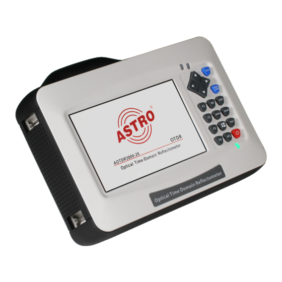
VFL (Visual Fault Locator) module OPM (Optical Power Meter) module The AOTDR features a CE marking. This confirms that the product DRAFT VERSION conforms to the relevant CE directives and adheres to the require- ments specified therein. Operating manual AOTDR -... - Page 14 [6] Button area DRAFT VERSION Figure 1: AOTDR Port 1: Includes AOTDR Test port (FC/UPC), Visual Fault Locator port (optional), Power Meter port (optional), Touch pen and 2x USB A type Arrow buttons: Move the cursor, navigate between menus or files ...
- Page 15 Function modules area: Here you can enter the settings for the modules OTDR (Reflectometer), OPM (Optical Power Meter) and VFL (Visual Fault Locator). Basic state information area: displays date, time and charging status of the battery Operating manual AOTDR - Version 04-2021A page 15...
- Page 16 Test condition information area: displays condition information of test including: „PW (pulse width)“, „WL (wave length)“, resolution of x axis and y (dB/div), distance, averaging and total loss from cursor A to cursor B page 16 Operating manual AOTDR - Version 04-2021A...
- Page 17 [1] VFL mode indicator [2] Launching state indicator DRAFT VERSION Figure 4: VFL menu interface OPM module interface [1] Power value [2] Wavelength channel [3] Reference value Figure 5: OPM menu interface Operating manual AOTDR - Version 04-2021A page 17...
-
Page 18: Preparation
Preparation Turning the device on Press the power button of the AOTDR for more than two seconds until the power state indicator [3, left LED] turns green. When batte- ry power is low, a warning message will be displayed on the screen. - Page 19 Rub each other carefully to clean the contaminant. Repeat step 1-3. Open the protecting cover of the optical port of the AOTDR. Insert the connector of the fibre carefully into the optical port. HINWEIS Insert the connector carefully into the optical port.
-
Page 20: Introduction To Measuring With The Aotdr
Introduction to measuring with the AOTDR The purpose of measuring The AOTDR shows the back-scatter light power of the optical signal relative to the distance. With this information, the OTDR can measure a series of important information of an optical fibre such as the quality of the line, distance of the line, etc. - Page 21 Introduction to measuring with the AOTDR Curve with a jumper connected: Figure 7: curve with a jumper connected If there is an additional reflection peak in a tested trace, this may be caused by a connection point or some other reasons. Anyway, the appearance of the reflection peak shows that the two connec- ting surfaces of the connection are smooth.
- Page 22 The connector of the test fibre is broken or polluted. The launching port on the AOTDR is broken or polluted. The distance of the broken point or the distance from the initial connection is too close. Curve with non-reflective event:...
- Page 23 The situation that there is no reflection peak at the end of a trace, as shown above, should be paid attention on. If the distance of the tested fibre is known and the distance shown on the AOTDR is not equal to the real distance, this shows that the fibre might be broken down or twisted and the maximum bending radius of it is exceeded.
- Page 24 LD and pulse generator back scattering light launch splicing point signal processor breaking point photo detector Display Fresnel refl ection splice loss distance (x) Figure 12: working principle of the AOTDR page 24 Operating manual AOTDR - Version 04-2021A...
- Page 25 Introduction to measuring with the AOTDR Event types The events on trace are all the points that the value of power loss fluctuates abnormally. It usually contains various types of connection and bending, crack, broken etc. The event points marked on trace with special marks are the abnormal points in a fibre that cause the excursion of a normal trace.
-
Page 26: Setting Measurement Conditions
Test Wave: test wavelength of the OTDR, including 1310nm, 1550 nm and 1310 nm & 1550 nm (3 different modes) Test Mode: Auto Mode: The AOTDR will set the best parameters for the current test. Manual Mode: Parameters can be set manually. ... - Page 27 Figure 15: selecting the test wavelength HINWEIS The „Auto mode“ is not suitable to perform a blind area test. You must enter "Manual mode" and choose "Blind area test" to perform the blind area test. Operating manual AOTDR - Version 04-2021A page 27...
- Page 28 2. Select „Auto mode“ in test setting column on the left side of the screen: Figure 16: selecting „Manual mode“ DRAFT VERSION 3. Select the test wavelength: Figure 17: selecting the test wavelength page 28 Operating manual AOTDR - Version 04-2021A...
- Page 29 When "Test Range" is set to "Auto", the test will choose the proper range auto- DRAFT VERSION matically. Once you set the “Test range“, the „Pulse width”item will adjust automatically. You can also adjust it manually. Operating manual AOTDR - Version 04-2021A page 29...
- Page 30 Proper relationship between range (MR) and pulse width (PW) for user's reference: 100m 500m 10km 20km 40km 80km 120km 160km 240km 10ns 20ns 50ns 100ns 200ns 500ns DRAFT VERSION 1μs 2μs 5μs 10μs 20μs Figure 19: Relationship between range and pulse width page 30 Operating manual AOTDR - Version 04-2021A...
-
Page 31: Making Measurements
Making measurements Making measurements The AOTDR has two test modes: averaging test mode and realtime test mode. Averaging test mode Averaging test mode can calculate the data of a curve over a period of time and display as an aver- aging one. - Page 32 Confirm by pressing the OK button on the control panel of the device. Figure 23: Selecting the test range and pulse width page 32 Operating manual AOTDR - Version 04-2021A...
- Page 33 You can measure the distance from one point to another: Press the F1 button on the control panel to activate the cursor function Use the arrow buttons on the control panel to move cursor A or B. Operating manual AOTDR - Version 04-2021A page 33...
- Page 34 Making measurements The following guide shows what information you can get: DRAFT VERSION Figure 25: Overview of displayed values of distance measurement page 34 Operating manual AOTDR - Version 04-2021A...
- Page 35 Otherwise it will affect the effective resolution and an overlarge testing range will result in the generation of huge and useless amounts of data (see figure below). Figure 27: Proper testing range Operating manual AOTDR - Version 04-2021A page 35...
- Page 36 540 m by a large pulse width. When the pusle widht is decreased to 50 ns, this event can be detected. Figure 28: Proper pulse width page 36 Operating manual AOTDR - Version 04-2021A...
- Page 37 1310 nm and 1550 nm. This phenomenon indicates that this fibre is just bended at the first point. If it's possible, please always compare the point state under 1310 nm and 1550 nm and judge whether it's bended or squashed. Figure 30: Proper wavelength Operating manual AOTDR - Version 04-2021A page 37...
- Page 38 In averaging testing mode, a long testing time can reduce noise during the data sampling and improve precision to get a better and smoother curve. Figure 31: Proper test time DRAFT VERSION page 38 Operating manual AOTDR - Version 04-2021A...
-
Page 39: Expanding The Waveform And Moving The Display Area
You may press „Zoom","Move" and "Switch" button to adjust the curve to a better position. For more information please read the next sections. Operating manual AOTDR - Version 04-2021A page 39... - Page 40 CURSOR function. The activated cursor in the submenu entry „Cursor“ turns yellow, which me- ans it is active now. Moving the cursor: Use the arrow buttons to switch from cursor A to B, from B to AB and back to A. DRAFT VERSION page 40 Operating manual AOTDR - Version 04-2021A...
- Page 41 Use the arrow buttons to zoom in or out within the curve diagram. To reset the display of the curve, press the OK button on the control panel of the device. Figure 34: Horizontally zoomed display of the curve Operating manual AOTDR - Version 04-2021A page 41...
- Page 42 Use the arrow buttons to zoom in or out within the curve diagram. To reset the display of the curve, press the OK button on the control panel of the device. Figure 36: Vertically zoomed display of the curve page 42 Operating manual AOTDR - Version 04-2021A...
- Page 43 Use the arrow buttons to shift the curve diagram upwards, downwards, resp. to the left or right side. To reset the display of the curve, press the OK button on the control panel of the device. Figure 38: Horizontally shifted display of the curve (example) Operating manual AOTDR - Version 04-2021A page 43...
- Page 44 Press the F2 button again to activate the SHIFT function and use the arrow buttons to shift the dis- play of the curve to a proper position (see figure below). Figure 40: curve shifted to a proper position page 44 Operating manual AOTDR - Version 04-2021A...
- Page 45 Figure 42: current display switched to curve B HINWEIS Don‘t display more than 8 curves at a time. If you load more than 8 curves, the last one will overwrite the first one. Operating manual AOTDR - Version 04-2021A page 45...
- Page 46 Select „Add Event“ to add an event. HINWEIS Event addition may not operate successfully for events that are too close to each other. You may move the cursor a bit away and have another try. DRAFT VERSION page 46 Operating manual AOTDR - Version 04-2021A...
-
Page 47: File Operation
Press the right arrow key to move to the „File List“ window. Use the upper and lower arrow button to select the relevant curve file and press OK. Press F1 to load the curve. Operating manual AOTDR - Version 04-2021A page 47... - Page 48 Select „cut“ or „copy“ within the submenu to copy or move the curve file. Choose the target folder and press F1 to enter the FILE OPERATION interface. Select „paste“ within the submenu to finish the operation. DRAFT VERSION page 48 Operating manual AOTDR - Version 04-2021A...
- Page 49 Press the screen symbol button on the control panel of the device. You can then check the captured screen by pressing the FILE button on the control panel. The save path can be changed within the „File Setting“ menu. Operating manual AOTDR - Version 04-2021A page 49...
-
Page 50: Entering Characters
Within the „Device Directory“ section choose the upper or lower arrow key to select a root directory. Choose „Create Directory“ from the submenu. Input the desired name and press the OK button on the screen keyboard. page 50 Operating manual AOTDR - Version 04-2021A... -
Page 51: Flm Test
DRAFT VERSION Figure 46: FLM Test Select „FLM“ on the start screen to enter the FLM interface as shown below: Figure 47: FLM interface Operating manual AOTDR - Version 04-2021A page 51... - Page 52 After the setup is finished, press the ESC button on the control panel of the device and then press the F1 button to start the FLM test. Figure 49: FLM test Use the left and right arrow button to check detailed information of each event. page 52 Operating manual AOTDR - Version 04-2021A...
-
Page 53: Vfl (Visual Fault Locator) Module (Optional)
VFL (Visual Fault Locator) module (optional) VFL (Visual Fault Locator) module (optional) The AOTDR is equipped with a VFL module (650 nm) to easily detect a broken point of an optical network. To launch the VFL module, press the VFL button on the start screen. -
Page 54: Optical Power Meter Module (Optional)
Setting: set the offset value and display precision λ: switch the wavelength Common λ Recog: switch between common mode and wavelength detection mode HINWEIS The wavelength will not change automatically in common mode! page 54 Operating manual AOTDR - Version 04-2021A... -
Page 55: Background Information On Measurements
Terminology Near-end reflection: A reflection occurs in the gap between the AOTDR and the connector for the optical fibre cable. Losses and reflections of the connection points cannot be detected in the section. This section is called a dead zone. - Page 56 (RMS = 1). Dead zone: The locations where measurements cannot be made due to the effects of Fresnel reflection, connection points, etc. DRAFT VERSION page 56 Operating manual AOTDR - Version 04-2021A...
-
Page 57: Maintenance And Repair
Maintenance and repair Maintenance and repair Tipps The AOTDR uses a rechargable Li-ion battery. Please pay attention to the following: Keep the device dry and clean. Store it at room temperature (15 - 30 °C). Charge it monthly if you don't use it for a long time (more than once a month). - Page 58 Keep the optical port clean by using alcohol soaked cotton and recover the dust cap after use. Calibration We suggest to calibrate the AOTDR twice a year. For more information please contact us. page 58 Operating manual AOTDR -...
-
Page 59: Service Tasks
The device may need to be sent to the manu- facturer. Service tasks HINWEIS The device must only be operated with the original power supply unit! Operating manual AOTDR - Version 04-2021A page 59... -
Page 60: Troubleshooting
Find Ghost Common ghost Reconnect fault point of reflection event and caused by reduce reflection strength. continuous reflection of connector. If the problem cannot be resolved, please contact the ASTRO customer service. page 60 Operating manual AOTDR - Version 04-2021A... -
Page 61: Technical Data
195 x 141 x 44 Weight [kg] 0,9 (with battery) Power adapter, charge cord. Lithium battery, FC adapter, USB cable, Accessories quick guide, test report, CD, carrying bag, wrist strap Optional SC/LC adapter, launch cable box Operating manual AOTDR - Version 04-2021A page 61... - Page 62 Technical data DRAFT VERSION page 62 Operating manual AOTDR - Version 04-2021A...
- Page 63 Technical data DRAFT VERSION Operating manual AOTDR - Version 04-2021A page 63...
- Page 64 Internet: www.astro-kom.de All the information contained in this document has been checked in good faith. The ASTRO company cannot be held liable for any damage or injury arising in connection with the use of these operating instructions. Operating manual...
Need help?
Do you have a question about the AOTDR and is the answer not in the manual?
Questions and answers