Table of Contents
Advertisement
Quick Links
Advertisement
Table of Contents

Subscribe to Our Youtube Channel
Related Manuals for ASTRO VA-1842


Summary of Contents for ASTRO VA-1842
- Page 1 HDMI Protocol Analyzer VA-1842 Instruction Manual Ver.1.02...
- Page 3 HDMI Protocol Analyzer VA-1842 Instruction Manual 2017.4 Ver.1.02 ASTRODESIGN,Inc.
-
Page 5: Table Of Contents
About the VA-1842..........................1 1.1 Overview ..........................................1 1.2 Features ..........................................1 1.3 Names and Functions of Parts ..................................3 1.3.1 VA-1842 Front Panel ................................... 3 1.3.2 VA-1842 Side Panel .................................... 5 1.3.3 VA-1842 Rear Panel .................................... 6 1.3.4 Mouse Operation ....................................7 1.3.5 Icons ......................................... - Page 6 4.1.14 Audio Timing ....................................... 51 4.1.15 HDCP Status ...................................... 52 4.1.16 HDCP Config ...................................... 54 4.1.17 SCDC Status ...................................... 56 4.2 Monitor ..........................................57 4.2.1 DDC Monitor ......................................57 4.2.2 DDC Line Capture ....................................59 4.2.3 CEC Monitor ......................................60 4.2.4 CEC Send ......................................
- Page 7 Contents 5.2.13 Generate HDCP Status ................................134 5.2.14 ARC Status......................................136 5.2.15 DDC Output ...................................... 139 5.2.16 HDCP Config ....................................140 Chapter 6 Compliance Test ..........................141 6.1 HDMI1.4b Pretest ......................................141 6.1.1 HDMI Source Test .................................... 142 6.1.2 HDMI Source Test CDF ................................. 153 6.1.3 HDMI Sink Test ....................................
- Page 8 6.3.24 CECT 11.2.2 Routing Control ..............................206 6.3.25 CECT 11.2.3 System Standby ..............................207 6.3.26 CECT 11.2.4 One Touch Record .............................208 6.3.27 CECT 11.2.5 Timer Programming ............................210 6.3.28 CECT 11.2.6 System Information............................213 6.3.29 CECT 11.2.7 Deck Control .................................214 6.3.30 CECT 11.2.8 Tuner Control ...............................217 6.3.31 CECT 11.2.9 Vendor Specific Commands ..........................219 6.3.32 CECT 11.2.10 OSD Display ..............................220 6.3.33 CECT 11.2.11 Device OSD Name Transfer........................221...
- Page 9 Contents 7.1.2 Load ........................................261 7.1.3 Delete ........................................262 7.2 Emulate Mode ......................................... 263 7.3 EDID (Edit) ........................................263 7.4 EDID (Load File) ......................................264 7.5 Load Downstream EDID .................................... 264 7.6 CEC Config ........................................264 7.6.1 Address Setting....................................264 7.6.2 Support OP Code .....................................
- Page 10 10.1.2 HD_Normal (Monitor Using 1920X1080p as the Native Format) ................295 10.1.3 SD_Normal (Monitor Using 720X576p as the Native Format) ...................296 10.1.4 TV_Audio (Monitor Capable of Receiving Regular TV Format) ................297 10.1.5 AMP_Audio (Monitor Capable of Receiving Multiple Audio Signals) ..............298 10.1.6 3D_Mandatory (Monitor Capable of Receiving 3D Mandatory) ................299 10.1.7 3D_Secondary (Monitor Capable of Receiving Multiple 3D Formats) ..............300 10.1.8 HDMI10_EDID (HDMI 1.0 Monitor) ............................301...
- Page 11 11.1.7 ISRC1 Packet ....................................362 11.1.8 ISRC2 Packet ....................................362 11.1.9 Channel Status Bit ..................................363 11.1.10 Audio Timing ....................................363 11.1.11 Vendor Specific InfoFrame............................... 363 11.1.12 HDCP ........................................ 363 Chapter 12 VA-1842 Specifications ........................365 12.1 Log Data Structure ..................................... 365...
- Page 12 12.2 Connector Pin Assignment ..................................372 12.2.1 HDMI Connector .....................................372 12.2.2 TRIGGER Connector ..................................373 12.3 Option Specifications ....................................375 12.3.1 Through Box .....................................375 12.3.2 SCDC Cable .....................................376 12.4 VA-1842 Specifications ....................................377 12.4.1 General Specifications .................................377 12.4.2 Ratings ........................................378 12.4.3 Restrictions .......................................379 Chapter 13 Revision History..........................381...
-
Page 13: Before Operation
Before Operation Introduction Thank you for purchasing the VA-1842 HDMI Protocol Analyzer. This manual describes operating procedures, precautions, and other matters for when using the product. Inappropriate handling may lead to an accident so be sure to read this manual. - Page 14 ■ When connecting this product to another device (TV or DVD player), connect it with the supplied frame ground (FG) cord, etc. so that the FG is shared between the device and VA-1842. If this product is used without sharing the FG, there is a risk of it malfunctioning.
- Page 15 Before Operation ■ Be careful of glass shards from a broken LCD panel. If the LCD panel is damaged, take care not to cut your hands, etc. on glass shards. Touching a broken part may result in an injury. ■ The LCD panel is a high precision device so be careful with regard to the following points when handling.
- Page 16 Describes safety precautions, configuration of this manual, and the Before Operation contents of the product package. About the VA-1842 Provides an overview and describes the features of the VA-1842. Connecting with Peripheral Describes the control procedure of the VA-1842. Devices and Usage Examples...
-
Page 17: About The Va-1842
HDMI terminals such as set-top boxes and DVD players. In addition, the reception of sink device signals can also be checked by using the VA-1842 Generate function. This manual collectively refers to devices with HDMI input terminals but without HDMI output terminals such as monitors and TVs as receivers (monitors), and collectively refers to devices with both HDMI output terminals and input terminals which perform output based on input signals as repeaters. - Page 18 Hot Plugging Function Enables a reset to be applied to a transmitter without disconnecting and connecting a cable between the transmitter and VA-1842. Log Trigger Function Enables setting a trigger to retrieve ANALYZE data. ...
-
Page 19: Names And Functions Of Parts
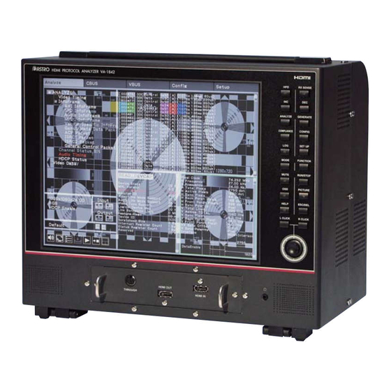
Chapter 1 About VA-1842 1.3 Names and Functions of Parts 1.3.1 VA-1842 Front Panel Displays the HDMI input video and analysis results. HDMI input connector Inputs the HDMI output of a DVD player or other device. Outputs the HDMI signals for the input of an HDMI TV, monitor, HDMI output connector or other device. - Page 20 Switches between receiver Performs the function operation of mode, repeater mode, and the active window. through mode. MODE key FUNCTION key When the LED lights, mutes the built-in speakers. Switches between RUN and STOP. When the LED goes out, turns MUTE key RUN/STOP key on the built-in speakers.
-
Page 21: Va-1842 Side Panel
1.3.2 VA-1842 Side Panel Ethernet port This port is for connecting to a LAN with an Ethernet cable. This port enables connecting with a PC to control the VA-1842 by sending USB port (B) and receiving commands. USB port (A) Connect the mouse or USB flash memory device. -
Page 22: Va-1842 Rear Panel
1.3.3 VA-1842 Rear Panel Power switch Turns the power of the VA-1842 on/off. Frame ground (FG) Shares the FG of a device to be connected with the VA-1842. AC input connector Connect the power cable. -
Page 23: Mouse Operation
Chapter 1 About VA-1842 1.3.4 Mouse Operation Left-click Performs the same operation as the L CLICK key. Right-click Performs the same operation as the R CLICK key. Wheel scroll Scrolls the active window up/down. Wheel click Performs the same operation as the FUNCTION key. - Page 24 OSD display Cursor Operated with the mouse or joy stick. This window is currently being used. It can be moved up, down, left, or right, and can be enlarged or Active window reduced. * Up to five windows including the active window can be displayed.
- Page 25 Chapter 1 About VA-1842 Inactive taskbar button This is the taskbar button for the inactive window. Displayed by right-clicking or pressing R CLICK outside of a Menu window window.
-
Page 26: Icons
1.3.5 Icons Name Icon Overview Video signals are always input when this is in the blue state. Video signal input icon The input of video signals is stopped when this is in the gray state. This is displayed in blue when the hot plug state of the input side is high. Input hot plug icon This is displayed in gray when the hot plug state of the input side is low. - Page 27 Chapter 1 About VA-1842 This is displayed in gray when AV mute is off. This is displayed in blue when scramble is on. Scramble icon This is displayed in gray when scramble is off. This is displayed in green when the hot plug state of the output side is high.
- Page 28 This is displayed in yellow when in through mode. The RUN/STOP icon is displayed in green when RUN (update) is selected. RUN/STOP icon The RUN/STOP icon is displayed in red when STOP (update) is selected. This is displayed in green when acquiring the log. LOG icon This is displayed in gray when log acquisition is stopped.
-
Page 29: Chapter 2 Connecting With Peripheral Devices And Usage Examples
Devices and Usage Examples 2.1 Connection Example in Receiver Mode Set the VA-1842 as a receiver (monitor) to perform HDMI protocol analysis of an HDMI output device. Measurement of the timing can be performed even for DVI output devices without an HDMI function. -
Page 30: Connection Example In Repeater Mode
Set the VA-1842 as a repeater to perform HDMI protocol analysis of an HDMI output device. By connecting an HDMI compatible monitor to the HDMI output of the VA-1842, you can check that an output device is operating normally as repeater support. -
Page 31: Connection Example In Through Mode
Set the VA-1842 to through mode to perform DDC and CEC line analysis of an HDMI input/output device. By connecting a through box to the HDMI THROUGH connector of the VA-1842, you can check that an HDMI input/output device is operating normally. -
Page 32: Connection Example When Generate
2.4 Connection Example when Generate Generate video signals from the VA-1842 and measure the display of HDMI compatible monitors. Device with HDMI input terminal LCD TV, etc. ∗ This can be used only in receiver mode. -
Page 33: Chapter 3 Menu Configuration
Menu Configuration Right-clicking or pressing R CLICK opens the window shown in the figure below so that you can select a menu. An overview of the menu configuration is shown in the following figure. Clicking or pressing L CLICK over OSD ON/OFF turns OSD display off. -
Page 34: Analyze
3.1 ANALYZE Use the ANALYZE menu when measuring input HDMI states. Right-click → left-click ANALYZE Mouse operation Press the ANALYZE key. Or press R CLICK → press L CLICK over ANALYZE Unit operation... -
Page 35: Generate
Chapter 3 Menu Configuration 3.2 GENERATE Use the GENERATE menu when generating video signals. Right-click → left-click GENERATE Mouse operation Press the GENERATE key. Or press R CLICK → press L CLICK over GENERATE Unit operation... -
Page 36: Compliance
3.3 COMPLIANCE Right-click → left-click COMPLIANCE Mouse operation Press the COMPLIANCE key. Or press R CLICK → press L CLICK over COMPLIANCE Unit operation... -
Page 37: Config
Chapter 3 Menu Configuration 3.4 CONFIG Right-click → left-click CONFIG Mouse operation Press the CONFIG key. Or press R CLICK → press L CLICK over CONFIG Unit operation... -
Page 38: Setup
3.5 SETUP Right-click → left-click SETUP Mouse operation Press the SETUP key. Or press R CLICK → press L CLICK over SETUP Unit operation... -
Page 39: Chapter 4 Source Analysis
Source ANALYSIS You can measure the timing of HDMI signals and decode and display InfoFrame and other content. The items of the measurement result display part are as shown in the following figure. -
Page 40: Analyze
4.1 ANALYZE 4.1.1 Video Timing Measures the timing of input. The display method is as follows. Right-click → left-click ANALYZE → left-click Video Timing Mouse operation Press the ANALYZE key. → press L CLICK over Video Timing Unit operation Press R CLICK → press L CLICK over ANALYZE... - Page 41 Chapter 4 Source ANALYSIS Item Period Details Clock Change Presence or absence of changing after pressing "Clear" Pixel Clock Pixel frequency H Frequency HSYNC frequency V Frequency VSYNC frequency H Total Pixels HTOTAL width H Active Pixels HDISP width H Sync Pixels HSYNC width H Back Porch Pixels HSYNC back porch width...
- Page 42 Data Enable HSYNC Horizontal Synchronization Signal Data Enable HSYNC VSYNC Vertical Synchronization Signal (when Non-Interlaced) Data Enable HSYNC VSYNC Vertical Synchronization Signal (when Interlaced)
-
Page 43: Avi Infoframe
Chapter 4 Source ANALYSIS 4.1.2 AVI InfoFrame Decodes and displays AVI InfoFrame of the HDMI input. AVI stands for Auxiliary Video Information, and refers to the information about the video output by the transmitter which is input. The display method is as follows. Right-click →... - Page 44 No Data Overscanned Scan Information Underscanned Future Bar Data not valid Vert.Bar Info valid Bar Information Horiz. Bar Info valid Vert. and Horiz. Bar Info valid No Active Format Information valid Active Format Present Active Format Information valid YCbCr4:2:2 RGB or YCbCr YCbCr4:4:4 YCbCr4:2:0 Same as picture aspect ratio...
- Page 45 Chapter 4 Source ANALYSIS AdobeRGB ITU-R BT.2020 Y'cC'bcC'rc ITU-R BT.2020 R'G'B' or Y'C'bC'r No data IT content IT content [X] XXX x XXX @ XXX / XXX Hz X : X Video Code Reserved No Video Code Available No Repetition Repetition pixel sent X times Reserved...
-
Page 46: Spd Infoframe
4.1.3 SPD InfoFrame Decodes and displays SPD InfoFrame of the HDMI input. SPD stands for Source Product Description, and refers to the information on the transmitter which is input. The display method is as follows. Right-click → left-click ANALYZE → left-click SPD InfoFrame Mouse operation Press the ANALYZE key. -
Page 47: Audio Infoframe
Chapter 4 Source ANALYSIS 4.1.4 Audio InfoFrame Decodes and displays Audio InfoFrame of the HDMI input. For Audio InfoFrame, the information about the audio output by the transmitter is input. The display method is as follows. Right-click → left-click ANALYZE → left-click Audio InfoFrame Mouse operation Press the ANALYZE key. - Page 48 MPEG2(multichannel) ATRAC One Bit Audio Dolby Digital+ DTS-HD WMA Pro Reserved Refer to Stream Header Audio Channel Count 2 - 8ch Refer to Stream Header 32 kHz 44.1 kHz 48 kHz Sampling Frequency 88.2 kHz 96 kHz 176.4 kHz 192 kHz Refer to Stream header 16 bit Sample Size...
- Page 49 Chapter 4 Source ANALYSIS NO ERROR Rsv of Data Byte6 ERROR NO ERROR Rsv of Data Byte7 ERROR NO ERROR Rsv of Data Byte8 ERROR NO ERROR Rsv of Data Byte9 ERROR NO ERROR Rsv of Data Byte10 ERROR...
-
Page 50: Mpeg Infoframe
4.1.5 MPEG InfoFrame Decodes and displays MPEG InfoFrame of the HDMI input. For MPEG InfoFrame, if the video sent by the transmitter has been converted from compressed video to non- compressed video, the video information of the compressed video is input. The display method is as follows. - Page 51 Chapter 4 Source ANALYSIS NO ERROR Rsv of Data Byte9 ERROR NO ERROR Rsv of Data Byte10 ERROR...
-
Page 52: Vendor Specific Infoframe
4.1.6 Vendor Specific InfoFrame Decodes and displays Vendor Specific InfoFrame of the HDMI input. With Vendor Specific InfoFrame, information about the 3D format and 4Kx2K is input. The display method is as follows. Right-click → left-click ANALYZE → left-click Vendor Specific InfoFrame Mouse operation Press the ANALYZE key. - Page 53 Chapter 4 Source ANALYSIS IEEE Registration ID = 000C03 H no video format Extended resolution format HDMI_Video_Format 3D format Reserved HDMI_Video_Format = Extended resolution format 4Kx2K 29.97/30Hz 4Kx2K 25Hz HDMI_VIC 4Kx2K 23.98/24Hz 4Kx2K 24Hz(SMPTE) Reserved HDMI_Video_Format = 3D format Frame packing Field alternative Line alternative Side-by-Side(Full)
- Page 54 Top-and-Bottom Side-by-Side(Half) Reserved 3D_Meta_present Not Present or Present 3D_Additionalinfo_present Not Present or Present 3D_DisparityData_present Not Present or Present 3D_F_Structure = side-by-side(half) Horizontal Odd/Left Odd/Right Horizontal Odd/Left Even/Right Horizontal Even/Left Odd/Right Horizontal Even/Left Even/Right 3D_Ext_Data Quincunx Odd/Left Odd/Right Quincunx Odd/Left Even/Right Quincunx Even/Left Odd/Right Quincunx Even/Left Even/Right Reserved...
-
Page 55: Dynamic Range And Mastering Infoframe
Chapter 4 Source ANALYSIS 4.1.7 Dynamic Range and Mastering InfoFrame Decodes and displays Dynamic Range and Mastering InfoFrame of the HDMI input. For Dynamic Range and Mastering InfoFrame, the HDR type and other related information are input. The display method is as follows. Right-click →... - Page 56 display_primaries_y2 X.XXXXX white_point_x X.XXXXX wite_point_y X.XXXXX max_dispay_mastering_luminance XXXXXX cd/m min_dispay_mastering_luminance X.XXXXX cd/m Maximu Content Light Level XXXXXX cd/m Maximu Frame-average Light Level XXXXXX cd/m...
-
Page 57: Gamut Metadata Packet
Chapter 4 Source ANALYSIS 4.1.8 Gamut MetaData Packet Decodes and displays Gamut Metadata Packet of the HDMI input. For Gamut Metadata Packet, Gamut boundary descriptions (GBD) and other related metadata information are input. The display method is as follows. Right-click → left-click ANALYZE → left-click Gamut MetaData Packet Mouse operation Press the ANALYZE key. - Page 58 Affected Gamut Seq Num XX H Current Gamut Seq Num XX H Intermediate packet in sequence First packet in sequence Packet Seq Last packet in sequence Only packet in sequence GBD profile = P1 and Packet Seq = First packet in sequence GBD Length H XX H GBD Length L...
-
Page 59: Acp Packet
Chapter 4 Source ANALYSIS 4.1.9 ACP Packet Decodes and displays ACP Packet of the HDMI input. ACP stands for Audio Content Protection, and refers to the information for the copyright protection of audio sent by the transmitter which is input. The display method is as follows. - Page 60 Number of permitted copies is '6' Number of permitted copies is '8' Number of permitted copies is '10' Number of permitted copies is '3' Number of permitted copy is not restricted. (Copy One Generation) CH < 2, fs < 48kHz, Q < 16bits CH <...
-
Page 61: Isrc1 Packet
Chapter 4 Source ANALYSIS 4.1.10 ISRC1 Packet Decodes and displays ISRC1 Packet of the HDMI input. ISRC stands for International Standard Recording Code, and refers to the audio source identification code which is input when the audio sent by the transmitter is DVD Audio. With ISRC1, the values of UPC_EAN_ISRC_numbers 0 to 15 as defined by the DVD Audio standard are applied in addition to the values defined by the HDMI standard. -
Page 62: Isrc2 Packet
4.1.11 ISRC2 Packet Decodes and displays ISRC2 Packet of the HDMI input. With ISRC2, the values of UPC_EAN_ISRC_numbers 16 to 31 as defined by the DVD Audio standard are applied. (Currently, these are reserved by the DVD Audio standard.) The display method is as follows. Right-click →... -
Page 63: General Control Packet
Chapter 4 Source ANALYSIS 4.1.12 General Control Packet Decodes and displays General Control Packet of the HDMI input. The display method is as follows. Right-click → left-click ANALYZE → left-click General Control Packet Mouse operation Press the ANALYZE key. → press L CLICK over General Unit operation Press R CLICK →... -
Page 64: Channel Status Bit
4.1.13 Channel Status Bit Decodes and displays Channel Status Bit (the sub codes that identify the sending device, sampling frequency, and so on) of the HDMI input audio streams. The display method is as follows. Right-click → left-click ANALYZE → left-click Channel Status Bit Mouse operation Press the ANALYZE key. - Page 65 Chapter 4 Source ANALYSIS Reserved - 2channel audio(0x02) Reserved - 2channel audio(0x03) Reserved - 4channel audio Audio = other than Linear PCM samples Default state Mode 00 Channel Status Mode Reserved General. Used temporarily Laser optical (Compact disc) Laser optical (Laser optical digital audio system) Laser optical (Mini disc system) Laser optical (Digital versatile disc) Laser optical (Reserved)
- Page 66 44.1kHz 48kHz 88.2kHz ( - HDMI Original ) 96kHz ( - HDMI Original ) 176.4kHz ( - HDMI Original ) 192kHz ( - HDMI Original ) 768kHz Reserved Level 2, ±1000ppm (default) Level 3, variable pitch Clock accuracy Level 1, ±50ppm - high accuracy Reserved 20bits Maximum sample length...
-
Page 67: Audio Timing
Chapter 4 Source ANALYSIS 4.1.14 Audio Timing Displays the constants (N and CTS) used when playing back the HDMI input audio clock from the video pixel clock and the input HDMI audio volume level. The display method is as follows. Right-click →... -
Page 68: Hdcp Status
Total number of stages connected to downstream * KSV values of the devices connected to downstream that have been KSVFIFO collected by the VA-1842 * Value for judging whether or not the KSV list generated by the VA-1842 is V’ appropriate * HDCP2.2... - Page 69 Type of stream identifier sent with RepeaterAuth_Stream_Manage * StreamID Information of the devices connected to downstream that is read with RxInfo RepeaterAuth_Send_ReceiverID_List * Receiver ID values of the devices connected to downstream that have been ReceiverIDList collected by the VA-1842 * * Displayed only when repeater.
-
Page 70: Hdcp Config
4.1.16 HDCP Config Set the settings related to HDCP. The display method is as follows. Right-click → left-click ANALYZE → left-click HDCP Config Mouse operation Press the ANALYZE key. → press L CLICK over HDCP Config Unit operation Press R CLICK → press L CLICK over ANALYZE The HDCP Config setting items are as follows. - Page 71 Send REAUTH_REQ Sends REAUTH_REQ. When the VA-1842 is used as a repeater, performs emulation for the device that outputs to the VA-1842 so VIRTUAL REPEATER MODE that there is an HDMI device connected to the output side of the VA-1842.
-
Page 72: Scdc Status
4.1.17 SCDC Status Displays the SCDC status on the HDMI receiver side. The display method is as follows. Right-click → left-click ANALYZE → left-click SCDC Status Mouse operation Press the ANALYZE key. → press L CLICK over SCDC Status Unit operation Press R CLICK →... -
Page 73: Monitor
4.2.1 DDC Monitor With the VA-1842, the data flowing on the DDC line between the input side of the VA-1842 and the HDMI source device in receiver mode and the data flowing on the DDC line between the HDMI sink device and HDMI source device in through mode can be displayed on the LCD of the unit front panel. - Page 74 [ A] Acknowledge [ N] Not Acknowledge Hotplug change [ HPD] [ SCDT] Whether or not video signal ( XXh XXm XXs XXX.Xms) Acquisition time The data types are classified as follows depending on the slave address. Slave Address Details A0 H EDID read command 60 H...
-
Page 75: Ddc Line Capture
Chapter 4 Source ANALYSIS 4.2.2 DDC Line Capture Displays the waveform of the DDC line (upper: serial data line [SDA], lower: serial clock line [SCL]) The display method is as follows. Right-click → left-click ANALYZE → left-click DDC Line Capture → wheel click over screen Mouse operation Press the ANALYZE key. -
Page 76: Cec Monitor
Initiator that an error has occurred in the CEC bus. (Error handling) This message is displayed when the VA-1842 detected this action. (If the low-level period is longer than 3.30-3.35 ms, this is... - Page 77 Bus Free Error This message is displayed when the resend time is shorter than specified in those parts of the items which are checked by the VA-1842 up to the command resend time of the CEC Compliance Test Item Check. ACK Error This message is displayed when there is not ACK for the CEC command.
-
Page 78: Cec Send
4.2.4 CEC Send Displays the send data setting screen. Specify the logical address of the send source from Initiator Setting. Specify the logical address of the send destination from Destination Setting. The display method is as follows. Right-click → left-click ANALYZE → left-click CEC Send Mouse operation Press the ANALYZE key. - Page 79 Active Source Inactive Source Sends Inactive Source. Broadcasts Request Active Request Active Source Source. If the VA-1842 is emulating two or more devices, changes the least significant bit of the Routing Change physical address currently being notified, and broadcasts Routing Change.
- Page 80 System Information Sends Get CEC Version. Get CEC Version Sends CEC Version. CEC Version Sends Get Menu Language. Set the VA-1842 to TV. Get Menu Language Set the send destination to TV. Sends Set Menu Language. Set the VA-1842 to TV.
- Page 81 Chapter 4 Source ANALYSIS Sends Play [Slow Forward Max Slow Forward Max Speed Speed]. Sends Play [Slow Reverse Min Slow Reverse Min Speed Speed]. Sends Play [Slow Reverse Slow Reverse Medium Speed Medium Speed]. Sends Play [Slow Reverse Max Slow Reverse Max Speed Speed].
- Page 82 Device OSD Name Sends Give OSD Name. Transfer Device Menu Sends Menu Request [Activate]. Activate Control Sends Menu Request Deactivate [Deactivate]. Query Sends Menu Request [Query]. Sends [Select] of User Control Select Pressed. Sends [Up] of User Control Pressed. Sends [Down] of User Control Down Pressed.
- Page 83 Chapter 4 Source ANALYSIS Sends [Reserved] of User Reserved (0x2E) Control Pressed. Sends [Next Favorite] of User Next Favorite Control Pressed. Sends [Channel Up] of User Channel Up Control Pressed. Sends [Channel Down] of User Channel Down Control Pressed. Sends [Previous Channel] of Previous Channel User Control Pressed.
- Page 84 Sends [Backward] of User Backward Control Pressed. Sends [Stop-Record] of User Stop-Record Control Pressed. Sends [Pause-Record] of User Pause-Record Control Pressed. Sends [Reserved] of User Reserved (0x4F) Control Pressed. Sends [Angle] of User Control Angle Pressed. Sends [Sub picture] of User Sub picture Control Pressed.
- Page 85 Chapter 4 Source ANALYSIS Sends [Power Toggle Function] Power Toggle Function of User Control Pressed. Sends [Power Off Function] of Power Off Function User Control Pressed. Sends [Power On Function] of Power On Function User Control Pressed. Reserved (0x6E) Sends [Reserved] of User Control Pressed.
- Page 86 Sends [Favorite Menu] of User Favorite Menu Control Pressed. Sends [Exit] of User Control Exit Pressed. Reserved (0x0E) Sends [Reserved] of User Control Pressed. Reserved (0x1F) Numbers 0 Sends [Numbers X] of User Control Pressed. Numbers 9 Sends [Dot] of User Control Pressed.
- Page 87 Chapter 4 Source ANALYSIS Sends [Mute] of User Control Mute Pressed. Sends [Play] of User Control Play Pressed. Sends [Stop] of User Control Stop Pressed. Sends [Pause] of User Control Pause Pressed. Sends [Record] of User Control Record Pressed. Sends [Rewind] of User Control Rewind Pressed.
- Page 88 P sends [Pause-Record Pause-Record Function Function] of User Control Pressed. Sends [Stop Function] of User Stop Function Control Pressed. Sends [Mute Function] of User Mute Function Control Pressed. Sends [Restore Volume Restore Volume Function Function] of User Control Pressed. Sends [Tune Function] of User Tune Function Control Pressed.
- Page 89 Chapter 4 Source ANALYSIS Sends Set System Audio Mode [ON]. Set System Audio Mode ON Sends Set System Audio Mode [ON] by broadcast after sending. Sends Set System Audio Mode [OFF]. Set System Audio Mode OFF Sends Set System Audio Mode [OFF] by broadcast after sending.
-
Page 90: Cec Status
4.2.5 CEC Status Display the current VA-1842 status. For the status of the VA-1842, there is the case where it is changed by a CEC command from an external source and the case where it is changed from the VA-1842 unit. - Page 91 Displays the currently emulated TUNER STATUS status. Displays the currently emulated menu status. Device Menu Status * This is enabled only when the VA-1842 is emulating a TV. UI Command Status Displays the sent UI command status. Displays the currently emulated device OSD name.
-
Page 92: Cec Line Capture
4.2.6 CEC Line Capture Displays the waveform of the CEC line. The display method is as follows. Right-click → left-click ANALYZE → left-click CEC Line Capture → wheel click over screen Mouse operation Press the ANALYZE key. → press L CLICK over CEC Line Unit operation Press R CLICK →... -
Page 93: Address Setting
Chapter 4 Source ANALYSIS 4.2.7 Address Setting With CEC, a logical address and physical address must be obtained by each device. The VA-1842 can freely emulate up to four logical addresses and physical addresses. If you check , select for the addresses you wish to set, and press GET, the logical address and physical address are set to be simulated. -
Page 94: Support Op Code
4.2.8 Support OP Code The OP codes with the checks are supported The display method is as follows. Right-click → left-click ANALYZE → left-click Support OP Code Mouse operation Press the ANALYZE key. → press L CLICK over Support OP Unit operation Press R CLICK →... - Page 95 Chapter 4 Source ANALYSIS Give Deck Status Supports receiving of Give Deck Status. Deck Status Supports receiving of Deck Status. Set Menu Language Supports receiving of Set Menu Language. Clear Analogue Timer Supports receiving of Clear Analogue Timer. Set Analogue Timer Supports receiving of Set Analogue Timer.
- Page 96 CEC Version Supports receiving of CEC Version. Get CEC Version Supports receiving of Get CEC Version. Vendor Command With ID Supports receiving of Vendor Command With ID. Clear External Timer Supports receiving of Clear External Timer. Set External Timer Supports receiving of Set External Timer. Report Short Audio Descriptor Supports receiving of Report Short Audio Descriptor.
-
Page 97: Support Language
Chapter 4 Source ANALYSIS 4.2.9 Support Language The display method is as follows. Right-click → left-click ANALYZE → left-click Support Language Mouse operation Press the ANALYZE key. → press L CLICK over Support Unit operation Press R CLICK → press L CLICK over ANALYZE Language Code(a) Language... - Page 98 Aragonese (hye) Armenian Araucanian Arapaho Artificial (Other) Arawak Assamese Asturian; Bable Athapascan languages Australian languages Avaric Avestan Awadhi Aymara Azerbaijani Code(b) Language Code(b) Language Banda Bamileke languages Bashkir Baluchi Bambara Balinese (eus) Basque Basa Baltic (Other) Beja Belarusian Bemba Bengali Berber (Other) Bhojpuri Bihari...
- Page 99 Chapter 4 Source ANALYSIS Kashubian Cushitic (Other) (wel) Welsh (ces) Czech Code(d) Language Code(d) Language Dakota Danish Dargwa Dayak Delaware Slave (Athapascan) deu (ger) German Dogrib Dinka Divehi; Dhivehi; Maldivian Dogri Dravidian (Other) Lower Sorbian Duala Dutch, Middle (ca.1050-1350) (nld) Dutch;...
- Page 100 Hausa Hawaiian Hebrew Herero Hiligaynon Himachali Hindi Hittite Hmong Hiri Motu (scr) Croatian Upper Sorbian Hungarian Hupa hye (arm) Armenian Code(i) Language Code(i) Language Iban Igbo (isl) Icelandic Sichuan Yi Inuktitut Interlingue Interlingua (International Auxiliary Iloko Language Association) Indic (Other) Indonesian Indo-European (Other) Ingush...
- Page 101 Chapter 4 Source ANALYSIS Lamba Latin Latvian Lezghian Limburgan; Limburger; Limburgish Lingala Lithuanian Mongo Lozi Luxembourgish; Letzeburgesch Luba-Lulua Luba-Katanga Ganda Luiseno Lunda Luo (Kenya and Tanzania) lushai Code(m) Language Code(m) Language (mkd) Macedonian Madurese Magahi Marshallese Maithili Makasar Malayalam Mandingo (mri) Maori Austronesian (Other)
- Page 102 Classical Newari; Old Newari; Nubian languages Classical Nepal Bhasa Chichewa; Chewa; Nyanja Nyamwezi Nyankole Nyoro Nzima Code(o) Language Code(o) Language Occitan (post 1500); Provencal Ojibwa Oriya Oromo Osage Ossetian; Ossetic Turkish, Ottoman (1500-1928) Otomian languages Code(p) Language Code(p) Language Papuan (Other) Pangasinan Pahlavi Pampanga...
- Page 103 Chapter 4 Source ANALYSIS Sami languages (Other) Lule Sami Inari Sami Samoan Skolt Sami Shona Sindhi Soninke Sogdian Somali Songhai Sotho, Southern Spanish; Castilian (alb) Albanian Sardinian Sranan Togo (scc) Serbian Serer Nilo-Saharan (Other) Swati Sukuma Sundanese Susu Sumerian Swahili Swedish Syriac Code(t)
- Page 104 Walloon Wolof Code(x) Language Code(x) Language Kalmyk; Oirat Xhosa Code(y) Language Code(y) Language Yapese Yiddish Yoruba Yupik languages Code(z) Language Code(z) Language Zapotec Zenaga Zhuang; Chuang (chi) Chinese Zande Zulu Zuni...
-
Page 105: Support Tuner
Chapter 4 Source ANALYSIS 4.2.10 Support Tuner The display method is as follows. Right-click → left-click ANALYZE → left-click Support Tuner Mouse operation Press the ANALYZE key. → press L CLICK over Support Tuner Unit operation Press R CLICK → press L CLICK over ANALYZE Digital Service 1 Digital Broadcast System1 Digital Broadcast System... - Page 106 Analogue Frequency1 Cable / Satellite / Terrestria Broadcast System1 Analogue Frequency Analogue Service 2 2Byte DATA Analogue Broadcast Type2 Analogue Frequency2 Broadcast System Broadcast System2 PAL B/G / SECAM L / PAL M / Analogue Service 3 NTSC M / PAL I / SECAM DK / Analogue Broadcast Type3 Analogue Frequency3 SECAM B/G / SECAM L / PAL DK...
-
Page 107: Support Timer
Chapter 4 Source ANALYSIS 4.2.11 Support Timer The display method is as follows. Right-click → left-click ANALYZE → left-click Support Timer Mouse operation Press the ANALYZE key. → press L CLICK over Support Timer Unit operation Press R CLICK → press L CLICK over ANALYZE Analogue Timer Setting Set the Analogue Timer settings. -
Page 108: Device Information
4.2.12 Device Information The display method is as follows. Right-click → left-click ANALYZE → left-click Device Information Mouse operation Press the ANALYZE key. → press L CLICK over Device Unit operation Press R CLICK → press L CLICK over ANALYZE Information Vendor ID 3Byte DATA... -
Page 109: Response Setting
Chapter 4 Source ANALYSIS 4.2.13 Response Setting Sets the settings for the responses for received data. If these settings are not set, responses are made in accordance with the CEC standard. Responses which are exceptions to what is set here can be returned or no response can be returned. The display method is as follows. -
Page 110: Original Command Setting
4.2.14 Original Command Setting You can create an original CEC command here and then send the command with CEC Send. The display method is as follows. Right-click → left-click ANALYZE → left-click Original Command Setting Mouse operation Press the ANALYZE key. →... -
Page 111: Bit Timing Setting
Chapter 4 Source ANALYSIS 4.2.15 Bit Timing Setting You can set original CEC data bit timing here. The display method is as follows. Right-click → left-click ANALYZE → left-click Bit Timing Setting Mouse operation Press the ANALYZE key. → press L CLICK over Bit Timing Unit operation Press R CLICK →... -
Page 112: Frame Communication Setting
4.2.16 Frame Communication Setting An arbitration error can be generated for a part with checked below the waveform. The display method is as follows. Right-click → left-click ANALYZE → left-click Frame Communication Setting Mouse operation Press the ANALYZE key. → press L CLICK over Frame Unit operation Press R CLICK →... -
Page 113: Arc Status
Chapter 4 Source ANALYSIS 4.3 ARC Status Changes the status of Audio Return Channel. The display method is as follows. Right-click → left-click ANALYZE → left-click ARC Status Mouse operation Press the ANALYZE key. → press L CLICK over ARC Status Unit operation Press R CLICK →... - Page 114 The audio frequencies and audio volumes with the selected for either Type Output Enable 1 or Type 2 among those with the checked for 1CH to 8CH are sent. COAX Input Sends ARC based on the information from coaxial audio. Pro or Consumer Mode Consumer...
- Page 115 Chapter 4 Source ANALYSIS Experiment products not for commercial sale Not define. Reserved Not define. Reserved, espect 000 0000 and 000 0001 L Do not take into account. Source number 1 - 15 CH Channel Do not take into account. A - O (0x1:A;...
-
Page 116: Video Data
4.4 Video Data Acquires the video data. The display method is as follows. Right-click → left-click ANALYZE → left-click Video Data → wheel click over screen Mouse operation Press the ANALYZE key. → press L CLICK over Video Data Unit operation Press R CLICK →... - Page 117 Chapter 4 Source ANALYSIS sYCC601 Adobe YCC601 Adobe RGB ITU-R BT.2020 Y'cC'bcC'rc ITU-R BT.2020 R'G'B' or Y'C'bC'r Color Type = YCbCr4:4:4 or YCbCr4:2:2 Limited Range Full Range Reserved Reserved Quantization Range Color Type = RGB Default Limited Range Full Range Reserved Clear Clears the video data of 1 acquired pixel.
-
Page 118: Lipsync
Audio Displays and changes the audio latency of the EDID set on the VA-1842. Video Displays and changes the interlaced video latency of the EDID set on the VA-1842. Interlaced Audio Displays and changes the interlaced audio latency of the EDID set on the VA-1842. - Page 119 Chapter 4 Source ANALYSIS...
-
Page 121: Chapter 5 Signal Generate
Signal Generate Generate video signals, etc. The items of the measurement result display part are as shown in the following figure. -
Page 122: General Setting
5.1 General Setting Configures the settings of video signal and audio signal generation, HDCP ON/OFF, and packets and patterns used to generate signals. The display method is as follows. Right-click → left-click GENERATE → left-click Generate Setting Mouse operation Press the GENERATE key. →... - Page 123 Chapter 5 Signal Generate When is checked, lipsync operates. Reads the EDID of the send destination and sends a video Auto Correction (EDID) signal and audio signal to match it. Sends the video signal for the set time portion Lipsync Video First first.
- Page 124 Frame W Raster R Raster G Raster B Raster Window Random Color Bar...
- Page 125 Chapter 5 Signal Generate 3D Checker (When Generate Timing is Frame Packing) (When Generate Timing is 2D) Cross Hatch The output video data actually becomes 8 bits.
-
Page 126: Detail
5.2 Detail 5.2.1 GenerateTiming Sets the video timing. The display method is as follows. Right-click → left-click GENERATE → left-click Generate Timing Mouse operation Press the GENERATE key. → press L CLICK over Generate Unit operation Press R CLICK → press L CLICK over GENERATE Timing Setting Item Settings... - Page 127 Chapter 5 Signal Generate H Front Porch Pixels HSYNC front porch width of video timing selected in Video Code H Sync Polarity HSYNC polarity of video timing selected in Video Code V Total Lines VTOTAL width (1 frame unit) of video timing selected in Video Code V Active TOTAL VDISP width (1 frame unit) of video timing selected in Video Code V Active Field1...
-
Page 128: Avi Infoframe
5.2.2 AVI InfoFrame Sets the AVI InfoFrame settings. The display method is as follows. Right-click → left-click GENERATE → left-click AVI InfoFrame Mouse operation Press the GENERATE key. → press L CLICK over AVI Unit operation Press R CLICK → press L CLICK over GENERATE InfoFrame Setting Item Settings... - Page 129 Chapter 5 Signal Generate H Bar Info valid V & H Bar Info valid No Active Format Information Active Format Present Active Format Information present YCbCr4:2:2 RGB or YCbCr YCbCr4:4:4 YCbCr4:2:0 Same as picture aspect ratio 4:3(center) 16:9(center) 14:9(center) box 16:9(top) box...
- Page 130 Reserved No Video Code Available No Repetition Repetition pixel sent X times Reserved Graphics Photo IT Content Type Cinema Game Limited Range Full Range YCC Quantization Range Reserved Reserved Line Number of End of Top 0 to FFFF Bar (ETB) Line Number of Start of 0 to FFFF Bottom Bar (SBB)
-
Page 131: Spd Infoframe
Chapter 5 Signal Generate 5.2.3 SPD InfoFrame Sets the SPD InfoFrame settings. The display method is as follows. Right-click → left-click GENERATE → left-click SPD InfoFrame Mouse operation Press the GENERATE key. → press L CLICK over SPD Unit operation Press R CLICK →... -
Page 132: Audio Infoframe
5.2.4 Audio InfoFrame Sets the Audio InfoFrame settings. The display method is as follows. Right-click → left-click GENERATE → left-click Audio InfoFrame Mouse operation Press the GENERATE key. → press L CLICK over Audio Unit operation Press R CLICK → press L CLICK over GENERATE InfoFrame Displayed item Description... - Page 133 Chapter 5 Signal Generate Refer to Stream Header Audio Channel Count 2 - 8ch Refer to Stream Header 32 kHz 44.1 kHz 48 kHz Sampling Frequency 88.2 kHz 96 kHz 176.4 kHz 192 kHz Refer to Stream header 16 bit Sample Size 20 bit 24 bit...
-
Page 134: Mpeg Infoframe
5.2.5 MPEG InfoFrame Sets the MPEG InfoFrame settings. The display method is as follows. Right-click → left-click GENERATE → left-click MPEG InfoFrame Mouse operation Press the GENERATE key. → press L CLICK over MPEG Unit operation Press R CLICK → press L CLICK over GENERATE InfoFrame Displayed item Description... -
Page 135: Vendor Specific Infoframe
Chapter 5 Signal Generate 5.2.6 Vendor Specific InfoFrame Sets the Vendor Specific InfoFrame settings. The display method is as follows. Right-click → left-click GENERATE → left-click Vendor Specific InfoFrame 1/2/3 Mouse operation Press the GENERATE key. → press L CLICK over Vendor Specific Unit operation Press R CLICK →... - Page 136 Line alternative Side-by-Side(Full) L + depth L + depth + graphics + graphics-depth Top-and-Bottom Reserved Side-by-Side(Half) 3D_Meta_present 0H or 1H 3D_Structure = side-by-side(half) Horizontal Odd/Left Odd/Right Horizontal Odd/Left Even/Right Horizontal Even/Left Odd/Right Horizontal Even/Left Even/Right 3D_Ext_Data Quincunx Odd/Left Odd/Right Quincunx Odd/Left Even/Right Quincunx Even/Left Odd/Right Quincunx Even/Left Even/Right Reserved...
- Page 137 Chapter 5 Signal Generate Quincunx Even/Left Even/Right Reserved 3D_ Additionalinfo_present = Present 3D_DualView Normal 3D or DualView No Indication The right view originates 3D_ViewDependency The left view originates Both views No Indication Use right 3D view 3D_Preferred2DView Use left 3D view Don’t Care 3D_DisparityData_present = Present 3D_DisparityData_version...
-
Page 138: Dynamic Range And Mastering Infoframe
5.2.7 Dynamic Range and Mastering InfoFrame Sets the Dynamic Range and Mastering InfoFrame settings. The display method is as follows. Right-click → left-click GENERATE → left-click Dynamic Range and Mastering InfoFrame Mouse operation Press the GENERATE key. → press L CLICK over Dynamic Unit operation Press R CLICK →... - Page 139 Chapter 5 Signal Generate display_primaries_x1 X.XXXXX display_primaries_y1 X.XXXXX display_primaries_x2 X.XXXXX display_primaries_y2 X.XXXXX white_point_x X.XXXXX wite_point_y X.XXXXX max_dispay_mastering_luminance XXXXXX cd/m min_dispay_mastering_luminance X.XXXXX cd/m Maximu Content Light Level XXXXXX cd/m Maximu Frame-average Light Level XXXXXX cd/m...
-
Page 140: Gamut Meta Data Packet
5.2.8 Gamut Meta Data Packet Sets the Gamut MetaData Packet settings. The display method is as follows. Right-click → left-click GENERATE → left-click Gamut MetaData Packet Mouse operation Press the GENERATE key. → press L CLICK over Gamut Unit operation Press R CLICK →... - Page 141 Chapter 5 Signal Generate 8bit GBD Color Precision 10bit 12bit Format Flag = Vertices/Facets ITU-R BT.709(using RGB) xvYCC601(IEC 61966-2-4-SD)(using YCbCr) GBD Color Space xvYCC709(IEC 61966-2-4-HD)(using YCbCr) Format Flag = Range Reserved GBD Color Space RGB expression of xvYCC601 RGB expression of xvYCC709 Format Flag = Vertices/Facets Facet Mode 0 or 1...
-
Page 142: Acp Packet
5.2.9 ACP Packet Sets the ACP Packet settings. The display method is as follows. Right-click → left-click GENERATE → left-click ACP Packet Mouse operation Press the GENERATE key. → press L CLICK over ACP Unit operation Press R CLICK → press L CLICK over GENERATE Packet Displayed item Description... - Page 143 Chapter 5 Signal Generate CH < 2, fs < 48kHz, Q < 16bits CH < 2, fs&Q is not restricted Quality CH&fs&Q is not restricted CH is not restricted, fs < 48kHz, Q < 16bits not present Transaction reserved Count_A XX times Count_S XX times...
-
Page 144: Isrc Packet
5.2.10 ISRC Packet Sets the ISRC Packet settings. The display method is as follows. Right-click → left-click GENERATE → left-click ISRC Packet Mouse operation Press the GENERATE key. → press L CLICK over ISRC Unit operation Press R CLICK → press L CLICK over GENERATE Packet Displayed item Description... -
Page 145: Other Infoframe
Chapter 5 Signal Generate 5.2.11 Other InfoFrame Allows you to set InfoFrame or Packet independently. The display method is as follows. Right-click → left-click GENERATE → left-click Other InfoFrame Mouse operation Press the GENERATE key. → press L CLICK over Other Unit operation Press R CLICK →... - Page 146 SPD InfoFrame (0x83) Audio InfoFrame (0x84) MPEG InfoFrame (0x85)
-
Page 147: Audio
Chapter 5 Signal Generate 5.2.12 Audio Sets the audio settings. The display method is as follows. Right-click → left-click GENERATE → left-click Audio Mouse operation Press the GENERATE key. → press L CLICK over Audio Unit operation Press R CLICK → press L CLICK over GENERATE Items Description Sampling Frequency... - Page 148 Liner PCM sample Audio Other than liner PCM sample Copyright Copy / Copyright no copyright Without pre-emphasis With 50/15 us pre emphasis Reservrd-2channel audio(0x02) Emphasis Reservrd-2channel audio(0x03) Reservrd-4channel audio Default State Reserved Mode 00 Channel Status Mode Reserved General. Used temporarily Laser optical (Compact disc) Laser optical (Laser optical digital audio system)
- Page 149 Chapter 5 Signal Generate Category code groups for solid state memory (Reserved) Experiment products not for commercial sale Not define. Reserved Not define. Reserved, aspect 000 0000 and 000 0001 L Do not take into account. Source number 1 - 15 CH Do not take into account.
-
Page 150: Generate Hdcp Status
Status The HDCP display items when GUI display are as follows. Displayed item Description HDCP1.4 Pseudo-random value used in HDCP authentication that the VA-1842 sent to the receiver or repeater device AKSV Key Selection Vector of the VA-1842 BKSV Key Selection Vector of the receiver or repeater device Ri’... - Page 151 Chapter 5 Signal Generate Pseudo-random value when authenticated with No_Stored_km H’ Authentication value calculated by the receiver or repeater device Pseudo-random nonce sent with LC_Init L’ Authentication value calculated by the receiver or repeater device Edkey_ks Section key information sent with SKE_Send_Eks Pseudo-random number sent with SKE_Send_Eks Number of times that RepeaterAuth_Send_ReceiverID_List has been resent seq_num_V...
-
Page 152: Arc Status
5.2.14 ARC Status Performs analysis of Arc Status. The display method is as follows. Right-click → left-click GENERATE → left-click ARC Status Mouse operation Press the GENERATE key. → press L CLICK over ARC Unit operation Press R CLICK → press L CLICK over GENERATE Status Items Description... - Page 153 Chapter 5 Signal Generate Without pre-emphasis With 50/15 us pre emphasis Reservrd-2channel audio(0x02) Emphasis Reservrd-2channel audio(0x03) Reservrd-4channel audio Default State Reserved Mode 00 Channel Status Mode Reserved General. Used temporarily Laser optical (Compact disc) Laser optical (Laser optical digital audio system) Laser optical (Mini disc system) Laser optical (Digital versatile disc)
- Page 154 Not define. Reserved, aspect 000 0000 and 000 0001 L L Bit Do not take into account. Source number 1 - 15 CH Do not take into account. Channel number A - O (0x1:A; 0x2:B; …… 0xF:O) Sampling frequency 44.1kHz no indicate 32kHz 48kHz...
-
Page 155: Ddc Output
Chapter 5 Signal Generate 5.2.15 DDC Output Performs I C access on the HDMI sender side. The display method is as follows. Right-click → left-click GENERATE → left-click DDC Output Mouse operation Press the GENERATE key. → press L CLICK over DDC Unit operation Press R CLICK →... -
Page 156: Hdcp Config
5.2.16 HDCP Config Set the settings related to HDCP on the HDMI sender side. The display method is as follows. Right-click → left-click GENERATE → left-click HDCP Config Mouse operation Press the GENERATE key. → press L CLICK over HDCP Unit operation Press R CLICK →... -
Page 157: Chapter 6 Compliance Test
Under the HDMI standard, it is mandatory to carry out compliance tests in order to prevent connectivity problems and other trouble. The VA-1842 can perform some of the compliance checks mainly of the source side, and display the corresponding result for each item. -
Page 158: Hdmi Source Test
TEST ID Description Checks whether or not the source device connected EDID-Related Behavior to the VA-1842 has read the EDIDs using DDC. Checks whether or not the device connected to the 7-19 Packet Types* VA-1842 is sending the ACP packets, ISRC1 packets, ISRC2 packets, and audio packets correctly. - Page 159 VA- 1842. Checks whether Pixel Repetition of the signals output 7-26 Pixel Repetition from the source device connected to the VA-1842 are reflected correctly in AVI InfoFrame. Checks the contents of AVI InfoFrame sent from the 7-27 AVI InfoFrame* source device connected to the VA-1842.
- Page 160 ACP_type does not equal Super Audio CD 0x03 (Super Audio CD) is not sent by ACP_type. ACP Reserved field is not ACP Reserved field is not 0. zero ACP PB0 value is not 0x01 PB0 is not 0x01 when ACP_type is 0x02 (DVD Audio). ISRC1 Packet is not ISRC1 packet is not sent transmitted...
- Page 161 Chapter 6 Compliance Test Pixel Clock is outside of When Video Code of AVI InfoFrame is at a timing of 60, 30, 24, 120, or allowable range 240 Hz, this frequency is not within +0.5% and -0.6% of the value specified in the format designated for Video Code.
- Page 162 VIC does not correspond to Video Code of AVI InfoFrame differs from the value specified in the video format timing format designated for Video Code. Aspect ratio does not match Aspect Ratio of AVI InfoFrame differs from the value specified in the aspect rate corresponding to format designated for Video Code.
- Page 163 Chapter 6 Compliance Test Channel Allocation (CA) does not match Channel The Allocation (CA) and Channel Count (CC) of Audio InfoFrame differ. Count (CC) Level Shift Value (LSV) != 0 The Channel Allocation (CA) value of Audio InfoFrame is not 0, and and Channel Level Shift Value (LSV) is not 0.
- Page 164 Channel Count (CC) != 0x00 The Channel Count (CC) value of Audio InfoFrame is neither 0x00 nor and Channel Count(CC) != 0x01. 0x01 Channel Allocation (CA) does not match Channel The Allocation (CA) and Channel Count (CC) of Audio InfoFrame differ. Count (CC) Level Shift Value (LSV) != 0 The Channel Allocation (CA) value of Audio InfoFrame is not 0, and...
- Page 165 Chapter 6 Compliance Test PB5 does not equal When 3D Structure of Vendor Specific InfoFrame is Top-of-Bottom, PB5 0b0110X000 is not 0b0110X000. sum != 0x00 The lower 8 bits of the CheckSum value of Vendor Specific InfoFrame are not 0. AVI InfoFrame version is not The setting is not 0x02.
- Page 166 PB5 through When Vendor Specific InfoFrame is (HB0, HB1, PB1, PB2, PB3=0x81, InfoFrame_Length do not x01, 0x03, 0x0C), the lower 8 bits of the total InfoFrame_Length value equal 0x00 from PB5 are not 0. PB4 does not equal 0x00 PB4 is not 0. VIC do not match indicated The VIC value differs from the value specified in the format designated for Video Code.
- Page 167 Chapter 6 Compliance Test H Sync Polarity does not This polarity differs from the value specified in the format designated for equal values for video format HDMI_VIC. V Total Lines do not equal This number of lines differs from the value specified in the format values for video format designated for HDMI_VIC.
- Page 168 For each packet type equal to 0x07. If these reserved fields are not zero then FAIL. If Audio InfoFrame Packet is detected at least once per two video fields then FAIL. 7-37 If One Bit Audio Sample subpacket jitter, relative to actual One Bit Audio Sample subpacket rate, ever exceeds one video horizontal line period plus a single subpacket period then FAIL.
-
Page 169: Hdmi Source Test Cdf
Chapter 6 Compliance Test 6.1.2 HDMI Source Test CDF The items to be tested can be selected if you set the specifications of the device under test (DUT) in the CDF (Capabilities Declaration Form) for executing HDMI CTS. Clicking SAVE saves the set CDF data. Clicking LOAD loads saved CDF data. - Page 170 Source_Additional_Format TEST ID7-27 Source_Non_CEA_Formats TEST ID7-27 Source_3D TEST ID7-38 Source_Mandatory_3D_Video_Formats TEST ID7-38 Source_Other_Primary_3D_Video_Formats TEST ID7-38 Source_4K2K TEST ID7-39 Source_4K2KVideo_formats TEST ID7-39 Source_Q_FullRange TEST ID7-23 Source_YQ_FullRange TEST ID7-24 Source_CN_Photo TEST ID7-27 Source_CN_Cinema TEST ID7-27 Source_CN_Game TEST ID7-27 Source_sYCC601 TEST ID7-40 Source_AdobeYCC601 TEST ID7-40 Source_AdobeRGB TEST ID7-40...
-
Page 171: Hdmi Sink Test
Description Loads the EDID of the sink device connected to the EDID Readable VA-1842, and checks its structure. If a sink device is not connected, “----” is displayed. Loads the EDID of the sink device connected to the VA-1842, and check whether it has the structure EDID VESA Structure defined by VESA. - Page 172 Incorrect Video Information Byte Video Information Byte is incorrect. Incorrect Preferred Timing bit The Preferred Timing bit is incorrect. Missing Preferred Timing descriptor There is no Preferred Timing descriptor. Missing Monitor Range Limits There is no Monitor Range Limits. Missing Monitor Name There is no Monitor Name.
- Page 173 Chapter 6 Compliance Test When Tag Code is 7 and Extended Tag Code is 5, Metadata P0 required if xvYCC supported Metadata P0 is not required if xvYCC is supported. When Tag Code is 7 and Extended Tag Code is 5, the Illegal gamut metadata indication gamut metadata is incorrect.
- Page 174 ・ When VSDB_Length is 8 or more, and bit 7-5 of byte 8 is 0, 0, 1, Sink_3D of CDF is Yes, and bit 7 of byte 9 is 0. ・ When VSDB_Length is 8 or more, and bit 7-5 of byte 8 3D video formats support not indicated despite 3D video formats applied is 1, 0, 1, Sink_3D of CDF is Yes and bit 7 of byte 11 is 0.
- Page 175 Chapter 6 Compliance Test ・ When VSDB_Length is 8 or more, and bit 7-5 of byte 8 is 0, 0, 1, Sink_3D_Additional of CDF is Yes, and bit 4-0 of byte 10 is 0. ・ When VSDB_Length is 8 or more, and bit 7-5 of byte 8 additional 3D video formats support not indicated despite additional 3D video format is 1, 0, 1, Sink_3D_Additional of CDF is Yes, and bit 4-0...
- Page 176 ・ When VSDB_Length is 8 or more, and bit 5 of byte 8 is 0,0,0, Sink_3D and Sink_4K2K of CDF are set to Yes. ・ When VSDB_Length is 8 or more, and bit 5 of byte 8 is 3D/4Kx2K video formats support not 0,1,0, Sink_3D and Sink_4K2K of CDF are set to Yes.
-
Page 177: Hdmi Sink Test Cdf
Chapter 6 Compliance Test 6.1.4 HDMI Sink Test CDF The items to be tested can be selected if you set the specifications of the device under test (DUT) in the CDF (Capabilities Declaration Form) for executing HDMI CTS. Clicking SAVE saves the set CDF data. Clicking LOAD loads saved CDF data. -
Page 178: Hdmi2.0 Cts
6.2 HDMI2.0 CTS Opens the items related to HDMI CTS. -
Page 179: Hdmi Source Test
Chapter 6 Compliance Test 6.2.1 HDMI Source Test When a test ID number is clicked with the mouse, the selected test is started. While testing is in progress, the EDIDs required for the tests are set automatically. The following shows the test list. For details on each test, refer to the MOI. - Page 180 Checks that the source device connected with VA- Source AVI InfoFrame for Y420VDB and HF1-51 1842 sends AVI InfoFrame correctly when sending Y420CMDB YCbCr4:2:0. Checks that the source device connected with VA- Source AVI InfoFrame and GCP – YC HF1-52 1842 sends AVI InfoFrame and GCP correctly when 4:2:0 BT.2020 sending BT.2020.
-
Page 181: Hdmi Source Test Cdf
Chapter 6 Compliance Test 6.2.2 HDMI Source Test CDF The items to be tested can be selected if you set the specifications of the device under test (DUT) in the CDF (Capabilities Declaration Form) for executing HDMI 2.0 CTS. Clicking SAVE saves the set CDF data. Clicking LOAD loads saved CDF data. - Page 182 Sets whether or not the DUT supports Traditional_HDR Source_HDR_Traditional_HDR output. Sets whether or not the DUT supports SMPTE_ST_2084 Source_HDR_SMPTE_ST_2084 output. Sets whether or not the DUT supports Hybrid Log-Gamma Source_HDR_Hybrid Log-Gamma output. Sets whether or not the DUT supports Sampling frequency Source_Audio_64 kHz output of 64 kHz.
-
Page 183: Hdmi Repeater Test
HDR content. Checks that the EDID of the repeater device connected HF3-23 Repeater Repeated Input Port HDR with the VA-1842 is set correctly. Repeater Repeated Input Port Sink Checks that the EDID of the repeater device connected HF3-24 Functionality HDR with the VA-1842 is set correctly. -
Page 184: Hdmi Repeater Test Cdf
6.2.4 HDMI Repeater Test CDF The items to be tested can be selected if you set the specifications of the device under test (DUT) in the CDF (Capabilities Declaration Form) for executing HDMI 2.0 CTS. Clicking SAVE saves the set CDF data. Clicking LOAD loads saved CDF data. -
Page 185: Cec1.4B Pretest
Chapter 6 Compliance Test 6.3 CEC1.4b Pretest Opens the items related to CEC1.4b CTS. -
Page 186: Cec Cts Cdf
6.3.1 CEC CTS CDF The items to be tested can be selected if you set the specifications of the device under test (DUT) in the CDF (Capabilities Declaration Form) for executing CEC CTS. Clicking SAVE saves the set CDF data. Clicking LOAD loads saved CDF data. -
Page 187: Cect 8
When “ALL TEST” is selected, the tests for the test IDs are started. When a test ID number is clicked with the mouse, only the selected test is started. The procedures for the tests performed with the VA-1842 are shown below. - Page 188 8.1-3 [Other than CEC Switch] The low time period of logical 0 data bits is Send the Abort message to the DUT. from 1.3 ms to 1.7 ms. The DUT responds with the Feature Abort message. The total time period of logical 0 data bits is from 2.05 ms to 2.75 ms.
-
Page 189: Cect 9
When “ALL TEST” is selected, the tests for the test IDs are started. When a test ID number is clicked with the mouse, only the selected test is started. The procedures for the tests performed with the VA-1842 are shown below. - Page 190 9.3-3 [Other than CEC Switch] [Other than CEC Switch] Send <Give Physical Address> to the DUT. DUT broadcasts <Report Physical Address> and tries to resend. [CEC Switch] Broadcast <Routing Information> [1.0.0.0] to the [CEC Switch] DUT. DUT broadcasts <Routing Information> and tries to resend.
-
Page 191: Cect10
When “ALL TEST” is selected, the tests for the test IDs are started. When a test ID number is clicked with the mouse, only the selected test is started. The procedures for the tests performed with the VA-1842 are shown below. - Page 192 10.2.2-1 Check the device connected to the VA-1842. DUT sends <Polling Message> to the logical Assert HPD. address of the recording device. DUT broadcasts that <Report Physical Address> of [Device Type] is Recording Device with the logical address of the recording device.
- Page 193 Chapter 6 Compliance Test 10.2.4-1 Check the device connected to the VA-1842. DUT sends <Polling Message> to the logical Assert HPD. address of the tuner. DUT broadcasts that <Report Physical Address> of [Device Type] is Tuner with the logical address of the tuner.
-
Page 194: Cect11.1 Tv / Display
6.3.5 CECT11.1 TV / Display The test types shown below can be selected. Test ID Function 11.1.1 One Touch Play 11.1.2 Routing Control 11.1.3 System Standby 11.1.4 One Touch Record 11.1.5 Timer Programming 11.1.6 System Information 11.1.7 Deck Control 11.1.8 Tuner Control 11.1.9 Vendor Specific Commands... -
Page 195: Cect 11.1.1 One Touch Play
When “ALL TEST” is selected, the tests for the test IDs are started. When a test ID number is clicked with the mouse, only the selected test is started. The procedures for the tests performed with the VA-1842 are shown below. -
Page 196: Cect 11.1.2 Routing Control
When “ALL TEST” is selected, the tests for the test IDs are started. When a test ID number is clicked with the mouse, only the selected test is started. The procedures for the tests performed with the VA-1842 are shown below. -
Page 197: Cect 11.1.3 System Standby
When “ALL TEST” is selected, the tests for the test IDs are started. When a test ID number is clicked with the mouse, only the selected test is started. The procedures for the tests performed with the VA-1842 are shown below. -
Page 198: Cect 11.1.4 One Touch Record
When “ALL TEST” is selected, the tests for the test IDs are started. When a test ID number is clicked with the mouse, only the selected test is started. The procedures for the tests performed with the VA-1842 are shown below. - Page 199 Chapter 6 Compliance Test Broadcast <Report Physical Address> as a DUT sends <Record On> ["External Physical 11.1.4-4 recording device. Address"] [External Physical Address] with Check that an external terminal is displayed on the the parameters in External Plug of the CDF. DUT.
- Page 200 Broadcast <Report Physical Address> from the DUT sends <Feature Abort>["Cannot Provide 11.1.4-13 logical address of the recording device. Source"] to the recording device. Send <Image View On> from logical address 4 to the DUT. Broadcast <Active Source> from logical address 4. Send <Record TV Screen>...
-
Page 201: Cect 11.1.5 Timer Programming
When “ALL TEST” is selected, the tests for the test IDs are started. When a test ID number is clicked with the mouse, only the selected test is started. The procedures for the tests performed with the VA-1842 are shown below. - Page 202 Set analog timer recording via the menu. DUT sends <Set Analogue Timer> with all 11.1.5-4 Send <Timer Status> indicating that media is parameters corresponding to the timer that available and timer programming has been set to the was set. DUT. (Repeat this procedure with the logical address changed to each of 1, 2, and 9.) Set external timer recording via the menu.
- Page 203 Chapter 6 Compliance Test Set analog timer recording via the menu. DUT sends <Clear Analogue Timer> with all 11.1.5-12 Send <Timer Status> indicating that media is parameters corresponding to the timer that available and timer programming has been set to the was cleared.
-
Page 204: Cect 11.1.6 System Information
When “ALL TEST” is selected, the tests for the test IDs are started. When a test ID number is clicked with the mouse, only the selected test is started. The procedures for the tests performed with the VA-1842 are shown below. -
Page 205: Cect 11.1.7 Deck Control
When “ALL TEST” is selected, the tests for the test IDs are started. When a test ID number is clicked with the mouse, only the selected test is started. The procedures for the tests performed with the VA-1842 are shown below. -
Page 206: Cect 11.1.8 Tuner Control
When “ALL TEST” is selected, the tests for the test IDs are started. When a test ID number is clicked with the mouse, only the selected test is started. The procedures for the tests performed with the VA-1842 are shown below. - Page 207 Chapter 6 Compliance Test Send <Tuner Device Status> that has the [Digital 11.1.8-3 DUT does not respond with <Feature Abort>. Service Identification] in Digital Tuner 1 of the CDF.
-
Page 208: Cect 11.1.9 Vendor Specific Commands
When “ALL TEST” is selected, the tests for the test IDs are started. When a test ID number is clicked with the mouse, only the selected test is started. The procedures for the tests performed with the VA-1842 are shown below. -
Page 209: Cect 11.1.10 Osd Display
When “ALL TEST” is selected, the tests for the test IDs are started. When a test ID number is clicked with the mouse, only the selected test is started. The procedures for the tests performed with the VA-1842 are shown below. -
Page 210: Cect 11.1.11 Device Osd Name Transfer
When “ALL TEST” is selected, the tests for the test IDs are started. When a test ID number is clicked with the mouse, only the selected test is started. The procedures for the tests performed with the VA-1842 are shown below. -
Page 211: Cect 11.1.12 Device Menu Control
When “ALL TEST” is selected, the tests for the test IDs are started. When a test ID number is clicked with the mouse, only the selected test is started. The procedures for the tests performed with the VA-1842 are shown below. - Page 212 Check that the DUT is in the state in which pressing DUT handles the remote control key press 11.1.12-3 a remote control key has an effect. locally. Send <Image View On> to the DUT. <User Control Pressed> is not sent. Broadcast <Active Source>.
-
Page 213: Cect 11.1.13 Remote Control Pass Through
When “ALL TEST” is selected, the tests for the test IDs are started. When a test ID number is clicked with the mouse, only the selected test is started. The procedures for the tests performed with the VA-1842 are shown below. - Page 214 Set the logical address to 5. DUT sends <User Control Pressed> with the 11.1.13-4 Check that the remote control of the DUT is set to correct key code for the pressed key. the audio system. DUT sends <User Control Released> when Press a remote control key to send to the audio the key is released.
-
Page 215: Cect 11.1.14 Give Device Power Status
When “ALL TEST” is selected, the tests for the test IDs are started. When a test ID number is clicked with the mouse, only the selected test is started. The procedures for the tests performed with the VA-1842 are shown below. -
Page 216: Cect 11.1.15 System Audio Control
When “ALL TEST” is selected, the tests for the test IDs are started. When a test ID number is clicked with the mouse, only the selected test is started. The procedures for the tests performed with the VA-1842 are shown below. - Page 217 Chapter 6 Compliance Test Broadcast <Set System Audio Mode>["On"] from DUT sends <System Audio Mode Request> 11.1.15-5 logical address 5. with no operand. Operate the DUT to set System Audio Control turns to Off. Set the logical address to 5. DUT sends one or more <Request Short 11.1.15-6 Broadcast <Report Physical Address>.
-
Page 218: Cect 11.1.16 Audio Rate Control
When “ALL TEST” is selected, the tests for the test IDs are started. When a test ID number is clicked with the mouse, only the selected test is started. The procedures for the tests performed with the VA-1842 are shown below. -
Page 219: Cect 11.1.17 Audio Return Channel Control
When “ALL TEST” is selected, the tests for the test IDs are started. When a test ID number is clicked with the mouse, only the selected test is started. The procedures for the tests performed with the VA-1842 are shown below. - Page 220 Check that the DUT is physical address 0.0.0.0. DUT does not send <Report ARC Initiated>. 11.1.17-5 Broadcast <Report Physical Address> with physical address 1.1.0.0. Send <Initiate ARC> to the DUT. Connect to an HDMI input without the Audio Return DUT does not send <Report ARC Initiated>. 11.1.17-6 Channel function.
-
Page 221: Cect 11.2.1 One Touch Play
When “ALL TEST” is selected, the tests for the test IDs are started. When a test ID number is clicked with the mouse, only the selected test is started. The procedures for the tests performed with the VA-1842 are shown below. -
Page 222: Cect 11.2.2 Routing Control
When “ALL TEST” is selected, the tests for the test IDs are started. When a test ID number is clicked with the mouse, only the selected test is started. The procedures for the tests performed with the VA-1842 are shown below. -
Page 223: Cect 11.2.3 System Standby
When “ALL TEST” is selected, the tests for the test IDs are started. When a test ID number is clicked with the mouse, only the selected test is started. The procedures for the tests performed with the VA-1842 are shown below. -
Page 224: Cect 11.2.4 One Touch Record
When “ALL TEST” is selected, the tests for the test IDs are started. When a test ID number is clicked with the mouse, only the selected test is started. The procedures for the tests performed with the VA-1842 are shown below. - Page 225 Chapter 6 Compliance Test 11.2.4-6 Check that the internal tuner is selected. DUT sends <Record Status> [Recording Check that the DUT is ready to record. currently selected source]. Send <Record On>. 11.2.4-7 Check that another signal source is selected. DUT sends <Record Status> [Recording Check that the DUT is ready to record.
-
Page 226: Cect 11.2.5 Timer Programming
When “ALL TEST” is selected, the tests for the test IDs are started. When a test ID number is clicked with the mouse, only the selected test is started. The procedures for the tests performed with the VA-1842 are shown below. - Page 227 Chapter 6 Compliance Test 11.2.5-4 Change the logical address to 1, 2 and 9, and send DUT sends <Set Analogue Timer>. <Report Physical Address>. Set the timer from the menu. 11.2.5-5 Change the logical address to 1, 2 and 9, and send DUT sends <Set External Timer>.
- Page 228 11.2.5-21 Check that the DUT is ready to record. DUT sends <Timer Status>. Send <Set Digital Timer>. DUT sends <Timer Cleared Status>. Send <Clear Digital Timer>. 11.2.5-22 Check that the DUT is ready to record. DUT sends <Timer Status>. Send <Set External Timer>. DUT sends <Timer Cleared Status>.
-
Page 229: Cect 11.2.6 System Information
When “ALL TEST” is selected, the tests for the test IDs are started. When a test ID number is clicked with the mouse, only the selected test is started. The procedures for the tests performed with the VA-1842 are shown below. -
Page 230: Cect 11.2.7 Deck Control
When “ALL TEST” is selected, the tests for the test IDs are started. When a test ID number is clicked with the mouse, only the selected test is started. The procedures for the tests performed with the VA-1842 are shown below. - Page 231 Chapter 6 Compliance Test 11.2.7-8 Check that the DUT is in the playback state. Enters the stopped state. Send <Play> [Play Still]. 11.2.7-9 Check that the DUT is in the idle state. Enters the stopped state or sends <Feature Send <Play> [Play Still]. Abort>.
- Page 232 11.2.7-14 Check that the DUT is in the following states. playing Sends <Deck Status> with the appropriate forwards parameter for the status. playing Reverse Paused Still Slow Forwards Slow Reverse Fast Forwards Fast Reverse Stopped (Idle) media present No media present Skip Forward or Winding(if applicable) Skip Reverse or Rewinding(if applicable) Recording(if applicable)
-
Page 233: Cect 11.2.8 Tuner Control
When “ALL TEST” is selected, the tests for the test IDs are started. When a test ID number is clicked with the mouse, only the selected test is started. The procedures for the tests performed with the VA-1842 are shown below. - Page 234 11.2.8-5 Check that the DUT is powered on and that Ignores the message. Analogue Service 1 in CDF is selected. Send <Select Analogue Service> [Analogue Service2] from logical address 15. 11.2.8-6 Check that the DUT is powered on and that Ignores the message.
-
Page 235: Cect 11.2.9 Vendor Specific Commands
When “ALL TEST” is selected, the tests for the test IDs are started. When a test ID number is clicked with the mouse, only the selected test is started. The procedures for the tests performed with the VA-1842 are shown below. -
Page 236: Cect 11.2.10 Osd Display
When “ALL TEST” is selected, the tests for the test IDs are started. When a test ID number is clicked with the mouse, only the selected test is started. The procedures for the tests performed with the VA-1842 are shown below. -
Page 237: Cect 11.2.11 Device Osd Name Transfer
When “ALL TEST” is selected, the tests for the test IDs are started. When a test ID number is clicked with the mouse, only the selected test is started. The procedures for the tests performed with the VA-1842 are shown below. -
Page 238: Cect 11.2.12 Device Menu Control
When “ALL TEST” is selected, the tests for the test IDs are started. When a test ID number is clicked with the mouse, only the selected test is started. The procedures for the tests performed with the VA-1842 are shown below. - Page 239 Chapter 6 Compliance Test 11.2.12-7 Check that the DUT is the active source. Send <Menu Request> [Activate]. Send <User Control Pressed> [Select]. Responds to each sent message. Send <User Control Released>. Send <User Control Pressed> [Up]. Send <User Control Released>. Send <User Control Pressed>...
-
Page 240: Cect 11.2.13 Remote Control Pass Through
When “ALL TEST” is selected, the tests for the test IDs are started. When a test ID number is clicked with the mouse, only the selected test is started. The procedures for the tests performed with the VA-1842 are shown below. -
Page 241: Cect 11.2.14 Give Device Power Status
When “ALL TEST” is selected, the tests for the test IDs are started. When a test ID number is clicked with the mouse, only the selected test is started. The procedures for the tests performed with the VA-1842 are shown below. -
Page 242: Cect 11.2.15 System Audio Control
When “ALL TEST” is selected, the tests for the test IDs are started. When a test ID number is clicked with the mouse, only the selected test is started. The procedures for the tests performed with the VA-1842 are shown below. - Page 243 11.2.15-14 Send <Request Short Audio Descriptor> with a Sends <Feature Abort> [Invalid Operand]. parameter of an unsupported format. 11.2.15-15 Connect the DUT to the VA-1842. Sends <Request Short Audio Descriptor> Broadcast <Report Physical Address>. with the parameter of the format in CDF.
-
Page 244: Cect 11.2.16 Audio Rate Control
When “ALL TEST” is selected, the tests for the test IDs are started. When a test ID number is clicked with the mouse, only the selected test is started. The procedures for the tests performed with the VA-1842 are shown below. -
Page 245: Cect 11.2.17 Audio Return Channel Control
When “ALL TEST” is selected, the tests for the test IDs are started. When a test ID number is clicked with the mouse, only the selected test is started. The procedures for the tests performed with the VA-1842 are shown below. - Page 246 Send <Terminate ARC>. 11.2.17-11 Connect an output of the DUT to the an input of the Does not send <Report ARC Initiated>. VA-1842, and an input of the DUT to an output of the VA-1842. Broadcast <Report Physical Address>. Send <Initiate ARC>.
-
Page 247: Cect 11.3 Cec Switch
When “ALL TEST” is selected, the tests for the test IDs are started. When a test ID number is clicked with the mouse, only the selected test is started. The procedures for the tests performed with the VA-1842 are shown below. - Page 248 Connect an output of the DUT to the an input of the Broadcasts <Routing Information> [1.1.0.0]. VA-1842, and an input of the DUT to an output of the VA-1842. Check that the output of the DUT is at position 1.
-
Page 249: Cect 12 Invalid Message Tests
When “ALL TEST” is selected, the tests for the test IDs are started. When a test ID number is clicked with the mouse, only the selected test is started. The procedures for the tests performed with the VA-1842 are shown below. -
Page 250: Hdcp1.4 Pretest
6.4 HDCP1.4 Pretest Opens the items related to HDCP1.4 CTS. -
Page 251: Hdcp1.4 Cts Pcp
Chapter 6 Compliance Test 6.4.1 HDCP1.4 CTS PCP The items to be tested can be selected if you set the specifications of the device under test (DUT) in the PCP (Product Capability Parameter) for executing HDCP1.4 CTS. List of HDCP1.4 CTS PCP items Settings Display Sets the maximum number of KSV that the source... -
Page 252: Hdcp1.4 Cts 1A
6.4.2 HDCP1.4 CTS 1A When a test ID number is clicked with the mouse, the selected test is started. While testing is in progress, the settings required for the tests are set automatically. The following shows the test list. Test list Name TEST ID Description... -
Page 253: Hdcp1.4 Cts 1B
Chapter 6 Compliance Test 6.4.3 HDCP1.4 CTS 1B When a test ID number is clicked with the mouse, the selected test is started. While testing is in progress, the settings required for the tests are set automatically. The following shows the test list. Test list Name TEST ID... - Page 254 Irregular procedure: (Second part of Performs a check of the HDCP protocol for when 1B-05 case2 authentication) READY was not sent with MAX_DEVS_EXCEEDED MAX_DEVS_EXCEEDED=1. Irregular procedure: (Second part of Performs a check of the HDCP protocol for when 1B-06 case1 authentication) READY is sent with MAX_CASCADE_EXCEEDED MAX_CASCADE_EXCEEDED...
-
Page 255: Hdcp1.4 Cts 2C
Chapter 6 Compliance Test 6.4.4 HDCP1.4 CTS 2C When a test ID number is clicked with the mouse, the selected test is started. While testing is in progress, the settings required for the tests are set automatically. The following shows the test list. Test list Name TEST ID... -
Page 256: Hdcp1.4 Cts 3A
6.4.5 HDCP1.4 CTS 3A When a test ID number is clicked with the mouse, the selected test is started. While testing is in progress, the settings required for the tests are set automatically. The following shows the test list. Test list Name TEST ID Description... -
Page 257: Hdcp1.4 Cts 3B
Chapter 6 Compliance Test 6.4.6 HDCP1.4 CTS 3B When a test ID number is clicked with the mouse, the selected test is started. While testing is in progress, the settings required for the tests are set automatically. The following shows the test list. Test list TEST ID Name... -
Page 258: Hdcp1.4 Cts 3C-1
6.4.7 HDCP1.4 CTS 3C-1 When a test ID number is clicked with the mouse, the selected test is started. While testing is in progress, the settings required for the tests are set automatically. The following shows the test list. Test list TEST ID Name Description... -
Page 259: Hdcp1.4 Cts 3C-2
Chapter 6 Compliance Test 6.4.8 HDCP1.4 CTS 3C-2 When a test ID number is clicked with the mouse, the selected test is started. While testing is in progress, the settings required for the tests are set automatically. The following shows the test list. Test list Name TEST ID... - Page 260 Performs a check of the HDCP protocol for when Irregular procedure: (Second part of 3C-2-8 MAX_DEVS_EXCEEDED bit = 1 is returned from authentication) MAX_DEVS_EXCEEDED downstream. Irregular procedure: (Second part of Performs a check of the HDCP protocol for when 3C-2-9 authentication) MAX_CASCADE_EXCEEDED bit = 1 is returned MAX_CASCADE_EXCEEDED...
-
Page 261: Hdcp2.2 Test
Chapter 6 Compliance Test 6.5 HDCP2.2 Test Opens the items related to HDCP2.2 CTS. -
Page 262: Hdcp2.2 Cts Pcp
Sets the video format for output during testing by the VA- Output Video Code 1842. Hotplug Pulse Width Sets the width of the HPD pulse output from the VA-1842. Test Time Out Sets the test timeout time. Sets the number of Device Count and Depth returned from RepeaterAuth_send_ReceiverID_List the VA-1842 in each test. -
Page 263: Hdcp2.2 Cts 1A
Chapter 6 Compliance Test 6.5.2 HDCP2.2 CTS 1A When a test ID number is clicked with the mouse, the selected test is started. While testing is in progress, the settings required for the tests are set automatically. The following shows the test list. Test list TEST ID Name... - Page 264 Performs a check of the HDCP protocol for when Regular Procedure – Receiver sends 1A-07 REAUTH_REQ is sent and authentication is REAUTH_REQ after ks performed again after sending SKE_Send_Eks. Irregular Procedure – RX certificate not Performs a check of the HDCP protocol for when 1A-08 received AKE_Send_Cert is not sent.
-
Page 265: Hdcp2.2 Cts 1B
Chapter 6 Compliance Test 6.5.3 HDCP2.2 CTS 1B When a test ID number is clicked with the mouse, the selected test is started. While testing is in progress, the settings required for the tests are set automatically. The following shows the test list. Test list Name TEST ID... - Page 266 Performs a check of the HDCP protocol for when Irregular Procedure – Re-authentication on 1B-08 REAUTH_REQ is sent and authentication is REAUTH_REQ performed again after authentication. Performs a check of the HDCP protocol for when Irregular Procedure – Rollover of seq_num_V 1B-09 seq_num_V is rolled over.
-
Page 267: Hdcp2.2 Cts 2C
Chapter 6 Compliance Test 6.5.4 HDCP2.2 CTS 2C When a test ID number is clicked with the mouse, the selected test is started. While testing is in progress, the settings required for the tests are set automatically. The following shows the test list. Test list TEST ID Name... -
Page 268: Hdcp2.2 Cts 3A
6.5.5 HDCP2.2 CTS 3A When a test ID number is clicked with the mouse, the selected test is started. While testing is in progress, the settings required for the tests are set automatically. The following shows the test list. Test list Name TEST ID Description... -
Page 269: Hdcp2.2 Cts 3B
Chapter 6 Compliance Test 6.5.6 HDCP2.2 CTS 3B When a test ID number is clicked with the mouse, the selected test is started. While testing is in progress, the settings required for the tests are set automatically. The following shows the test list. Test list TEST ID Name... -
Page 270: Hdcp2.2 Cts 3C-1
6.5.7 HDCP2.2 CTS 3C-1 When a test ID number is clicked with the mouse, the selected test is started. While testing is in progress, the settings required for the tests are set automatically. The following shows the test list. Test list TEST ID Name Description... - Page 271 Chapter 6 Compliance Test Performs a check of the HDCP protocol for when a Irregular Procedure – New Authentication receiver is connected to an output and a source 3C -05 during Locality Check device is connected to an input of the DUT, and initial authentication is started again after sending LC_Init.
-
Page 272: Hdcp2.2 Cts 3C-2
6.5.8 HDCP2.2 CTS 3C-2 When a test ID number is clicked with the mouse, the selected test is started. While testing is in progress, the settings required for the tests are set automatically. The following shows the test list. Test list TEST ID Name Description... - Page 273 Chapter 6 Compliance Test Performs a check of the HDCP protocol when a repeater is connected to an output and a source Regular Procedure – Receiver disconnect device is connected to an input of the DUT, and the 3C -15 after ks repeater is disconnected and connected and authentication is performed again after sending...
- Page 274 Performs a check of the HDCP protocol when a repeater is connected to an output and a source Regular Procedure – Propagation of device is connected to an input of the DUT, and 3C -24 HDCP1_DEVICE_DWONSTREAM flag RepeaterAuth_Send_ReceiverID_List with HDCP1_DEVICE_DWONSTREAM set is sent from the repeater to the DUT.
-
Page 275: Chapter 7 Device Config
Device Config You can configure the settings in Device Config and then save the set data to the VA-1842 or the USB flash memory device. Furthermore, you can also load saved configuration data. -
Page 276: Config File
Moves to the next folder up. When is selected for Internal, the configuration data is saved or a folder is created Internal in the VA-1842. When is selected for USB, the data is saved or a folder is created in the USB flash memory device. -
Page 277: Load
Loads the .cfg file with the name set in Name. Moves to the next folder up. Internal When is selected for Internal, the data in the VA-1842 is loaded. When is selected for USB, the data in the USB flash memory device is loaded. Address Displays the address to load the configuration data. -
Page 278: Delete
Deletes the .cfg file or folder with the name set in Name. Moves to the next folder up. Internal When is selected for Internal, the data or folder in the VA-1842 is deleted. When is selected for USB, the data or folder in the USB flash memory device is deleted. -
Page 279: Emulate Mode
Chapter 7 Device Config 7.2 Emulate Mode Item Description Receiver Sets the configuration data to be saved as the receiver mode. Repeater Sets the configuration data to be saved as the repeater mode. Through Sets the configuration data to be saved as the through mode. 7.3 EDID (Edit) Displays and changes the EDIDs. -
Page 280: Edid (Load File)
7.4 EDID (Load File) Open the window shown in 7.1.2 Load, and load only the EDIDs of the stored configuration data. * If you have a VA-1809, the DDC files or EDI files of the VA1809 can also be loaded. In other cases, the data is loaded in binary format. -
Page 281: Generate Setting
Chapter 7 Device Config 7.7 Generate Setting 7.7.1 Detail Configure the settings of video signal and audio signal generation, HDCP ON/OFF, and packets and patterns used to generate signals. For the setting items and details, refer to 5.1 General Setting. 7.7.2 Generate Timing Set the video timing. -
Page 282: Audio
7.7.12 Audio Set the audio settings. For the setting items and details, refer to 5.2.12 Audio. -
Page 283: Chapter 8 Setup
Setup Sets the items in the following figure. -
Page 284: Display Setup
8.1 Display Setup Set the LCD in DISPLAY SETUP. Item Description Sets the brightness of the OSD area. The value can be changed to any value from 0 OSD Brightness to 100. Sets the contrast of the OSD area. The value can be changed to any value from 0 to OSD Contrast 100. -
Page 285: Audio Setup
Chapter 8 Setup 8.2 Audio Setup Item Description Sets the speaker volume. The value can be changed to any value from 1 to Speaker Volume 100.* Sound Effect Sets the sound effect to ON/OFF. Speaker Select Set the channels to be output to the speakers. When Rx HDMI Input is selected, the sound from HDMI is output to the speakers. -
Page 286: Log Setup
8.3 Log Setup The logs of the items with selected for Packet and the DDC and CEC logs can be acquired. The logs can be acquired in text or HTML format. Logs are not acquired if Disabled is selected. -
Page 287: Action Setup
EDID Auto CheckSum Sets the EDID checksum automatically. EDID Physical Address Fixes the physical address set for the VA-1842. SCDC Scrambling_Statsu Fixes Scrambling_Status of SCDC to Enable regardless of the input status. When Generate Timing is changed, the items with the... -
Page 288: Device Information
Sets the MAC address of the VA-1842. Calibration Value Sets the calibration value of the VA-1842. Internal Timer Sets the time. License Indicates whether or not there is a license. ∗ The VA-1842 must be restarted after the Ethernet and other settings have been changed. -
Page 289: Initialize
Description Internal Memory initialize Initializes the configuration data saved to the VA-1842. Copies all the configuration data that is saved to the VA-1842 Internal Data Copy to USB to the USB flash memory device. Copies all the configuration data that is saved to the USB flash USB Data Copy to Internal Memory memory device to the VA-1842. -
Page 291: Chapter 9 Sub Window
Sub Window When a window is right-clicked, the corresponding sub window shown in the figure below appears. (2) Sub window of DDC Monitor (1) Sub window of InfoFrame items (excluding General (3) Sub window of CEC Monitor Control Packet) and Channel Status Bit of Source ANALYSIS (6) Sub window of Compliance (5) Sub window of other than (1) - Page 292 Item Supported functions Description Increments the program number of Config set in the Config INC (1) (2) (3) (4) (5) VA-1842. Decrements the program number of Config set in the Config DEC (1) (2) (3) (4) (5) VA-1842. Tile H (1) (2) (3) (4) (5) (6) Displays two windows vertically.
-
Page 293: Chapter 10 Internal Data
Internal Data 10.1 EDID The VA-1842 comes with sample data in the form of internal data. The internal data is contained in d config inside Config File of Device Config. The default settings are listed below. 2D_Normal (2D Monitor Capable of Receiving Multiple Formats) ... - Page 294 HF1-35-1 (21:9 Video Timing Test) HF1-35-2 (21:9 Video Timing Test) HF1-45 (Audio Sampling Frequency Test) HF1-51-1 (YCbCr4:2:0AVI InfoFrame Test) HF1-51-2 (YCbCr4:2:0AVI InfoFrame Test) HF1-51-3 (YCbCr4:2:0AVI InfoFrame Test) HF1-52-1 (BT.2020 Test) HF1-52-2 (BT.2020 Test) ...
- Page 295 Chapter 10 Internal Data Video Format (2D_Normal to 3D_Secondary) ◎: Native Format; ○: Supported format; -: Not supported Internal program 3D_M 3D_S ○ ○ ○ ○ ○ [01]640x480p @ 59.94/60Hz ◎ ○ ○ ◎ ○ ○ [02]720x480p @ 59.94/60Hz ○ ○...
- Page 296 ◎: Native Format; ○: Supported format; -: Not supported Internal program HDMI10 4Block H14b4K ○ ○ ○ ○ ○ [01]640x480p @ 59.94/60Hz ◎ ◎ ◎ ◎ ◎ [02]720x480p @ 59.94/60Hz ○ ○ ○ [03]720x480p-w @ 59.94/60Hz ○ ○ ○ ○ [04]1280x720p @ 59.94/60Hz ○...
- Page 297 Chapter 10 Internal Data Video Format (Compliance EDID) ◎: Native Format; ○: Supported format; -: Not supported CTS 7- CTS 7- CTS 7- CTS 7- Internal program 19_1 19_2 7-23 7-24 ○ ○ ○ ○ ○ ○ [01]640x480p @ 59.94/60Hz ◎...
- Page 298 CTS 7- CTS 7- CTS 7- CTS 7- Internal program 33_1 33_2 7-34 7-35 ○ ○ ○ ○ ○ [01]640x480p @ 59.94/60Hz ◎ ◎ ◎ ◎ ◎ [02]720x480p @ 59.94/60Hz ○ ○ ○ ○ ○ [03]720x480p-w @ 59.94/60Hz ○ ○ ○...
- Page 299 Chapter 10 Internal Data CTS 7- CTS 7- CTS 7- CTS 7- Internal program 7-36 38_1 38_2 38_3 7-40 ○ ○ ○ ○ [01]640x480p @ 59.94/60Hz ◎ ◎ ◎ ◎ ◎ ◎ [02]720x480p @ 59.94/60Hz ○ ○ ○ ○ ○ ○...
- Page 300 Internal program HF1-31-1 HF1-31-2 HF1-31-3 HF3-3 ○ ○ ○ ○ [01]640x480p @ 59.94/60Hz ◎ ◎ ◎ ◎ [02]720x480p @ 59.94/60Hz ○ ○ ○ [03]720x480p-w @ 59.94/60Hz ○ ○ ○ [04]1280x720p @ 59.94/60Hz ○ ○ ○ [05]1920x1080i @ 59.94/60Hz ○ ○ ○...
- Page 301 Chapter 10 Internal Data Audio Format (2D_Normal to 6G) Internal program 3D_M 3D_S ○ ○ ○ ○ ○ ○ Linear PCM 8ch ○ ○ Linear PCM 2ch ○ ○ ○ ○ ○ ○ ○ AC-3 MPEG1 MPEG2 ○ ○ ○ ○...
- Page 302 Audio Format (Compliance EDID) CTS 7- CTS 7- CTS 7- CTS 7- CTS 7- Internal program 7-1_1 19_1 19_2 ○ ○ ○ ○ ○ ○ Linear PCM 8ch Linear PCM 2ch ○ ○ ○ ○ AC-3 MPEG1 MPEG2 ○ ○ ○...
- Page 303 Chapter 10 Internal Data CTS 7- CTS 7- CTS 7- CTS 7- CTS 7- CTS 7- Internal program 38_1 38_2 38_3 ○ ○ ○ ○ ○ ○ Linear PCM 8ch Linear PCM 2ch ○ ○ ○ ○ ○ ○ AC-3 MPEG1 MPEG2 ○...
-
Page 304: 2D_Normal (2D Monitor Capable Of Receiving Multiple Formats)
10.1.1 2D_Normal (2D Monitor Capable of Receiving Multiple Formats) byte Item Setting value 07-00 Header 0x00FFFFFFFFFFFF00 09-08 ID Manufacturer Name 0x8F06 = ATO 0B-0A ID Product Code 0xB021 0F-0C ID Serial Number 0x00000001 Week of Manufacture 0x09 = 9 Year of Manufacture 0x19 = 2015 EDID... - Page 305 Chapter 10 Internal Data Green-x 0x11F = 0.339 Green-y 0x262 = 0.521 Blue-x 0x09F = 0.158 Blue-y 0x048 = 0.162 White-x 0x122 = 0x323 White-y 0x131 = 0.340 [Established Timings 1] 0x20 720x400 @ 70Hz 0b0 = not support 720x400 @ 88Hz 0b0 = not support 640x480 @ 60Hz 0b1 = support...
- Page 306 FLAG 0x0000 = Monitor Descriptor Reserved 0x00 Data Type Tag 0xFC = Monitor name, stored as ASCII Reserved 0x00 66-5F Monitor Name 0x56412D313834320A = VA-1842 6B-67 0x2020202020 7D-6C [Monitor Descriptor Description #2] 6D-6C FLAG 0x0000 = Monitor Descriptor Reserved 0x00...
- Page 307 Chapter 10 Internal Data YCbCr4:4:4 0b1 = support YCbCr4:2:2 0b1 = support total number of native formats 0b1 = 1 [Video Short Description] 0x4F Tag Code 0x02 = Video Short Description Length 0x0F Video Code/Native Format 0x82 = [2] = 720x480p / Native Format 0x01 = [1] = 640x480p 0x03 = [3] = 720x480pW 0x04 = [4] = 1280x720p...
- Page 308 Max Number of Audio#7 0x07 = 8ch Supported Sampling Frequency#7 0x7E = 44.1,48,88.2,96,176.4,192kHz User Define #7 0x01 = 1 Audio Format Code#8 0x0C = MAT(MLP) Max Number of Audio#8 0x07 = 8ch Supported Sampling Frequency#8 0x7E = 44.1,48,88.2,96,176.4,192kHz Audio Codec Vendor#8 0x00= 0 [Speaker Allocation Data Block] 0x83...
- Page 309 Chapter 10 Internal Data C2-C0 Horizontal Active Pixels 0x2D0 = 720dot Horizontal Blanking Pixels 0x8A = 138dot C5-C3 Vertical Active Lines 0x1E0 = 480H Vertical Blanking Lines 0x2D = 45H C9-C6 Horizontal sync offset 0x10 = 16dot Horizontal sync pulse width 0x3E = 62dot Vert sync offset 0x9 = 9H...
- Page 310 Interlace 0x0 = non-Interlace Stereo Mode 0x0 = Normal display, no stereo sync signal description1 0x3 = Digital Separate sync signal description2 0b1= Vertical Polarity positive sync signal description3 0b1 = Horizontal Polarity positive FE-F4 Reserved 0x00 Check sum 0x3A...
-
Page 311: Hd_Normal (Monitor Using 1920X1080P As The Native Format)
Chapter 10 Internal Data 10.1.2 HD_Normal (Monitor Using 1920X1080p as the Native Format) -
Page 312: Sd_Normal (Monitor Using 720X576P As The Native Format)
10.1.3 SD_Normal (Monitor Using 720X576p as the Native Format) -
Page 313: Tv_Audio (Monitor Capable Of Receiving Regular Tv Format)
Chapter 10 Internal Data 10.1.4 TV_Audio (Monitor Capable of Receiving Regular TV Format) -
Page 314: Amp_Audio (Monitor Capable Of Receiving Multiple Audio Signals)
10.1.5 AMP_Audio (Monitor Capable of Receiving Multiple Audio Signals) -
Page 315: 3D_Mandatory (Monitor Capable Of Receiving 3D Mandatory)
Chapter 10 Internal Data 10.1.6 3D_Mandatory (Monitor Capable of Receiving 3D Mandatory) -
Page 316: 3D_Secondary (Monitor Capable Of Receiving Multiple 3D Formats)
10.1.7 3D_Secondary (Monitor Capable of Receiving Multiple 3D Formats) -
Page 317: Hdmi10_Edid (Hdmi 1.0 Monitor)
Chapter 10 Internal Data 10.1.8 HDMI10_EDID (HDMI 1.0 Monitor) -
Page 318: Dvi_Edid (Dvi Monitor)
10.1.9 DVI_EDID (DVI Monitor) -
Page 319: 4Block_Edid (4-Block Edid Monitor)
Chapter 10 Internal Data 10.1.10 4Block_EDID (4-block EDID Monitor) -
Page 320: H14B4K_Edid (Hdmi 1.4B 4Kx2K Compatible Monitor)
10.1.11 H14b4K_EDID (HDMI 1.4b 4Kx2K Compatible Monitor) -
Page 321: Ycbcr420 (Ycbcr4:2:0 Compatible Monitor)
Chapter 10 Internal Data 10.1.12 YCbCr420 (YCbCr4:2:0 Compatible Monitor) -
Page 322: 6G_Edid (6G Compatible Monitor)
10.1.13 6G_EDID (6G Compatible Monitor) -
Page 323: Hdr_Edid (Hdr Compatible Monitor)
Chapter 10 Internal Data 10.1.14 HDR_EDID (HDR Compatible Monitor) -
Page 324: Cts7-1_1 (Edid Test)
10.1.15 CTS7-1_1 (EDID Test) -
Page 325: Cts7-1_2 (Edid Test)
Chapter 10 Internal Data 10.1.16 CTS7-1_2 (EDID Test) -
Page 326: Cts7-19_1 (Packet Test)
10.1.17 CTS7-19_1 (Packet Test) -
Page 327: Cts7-19_2 (Packet Test)
Chapter 10 Internal Data 10.1.18 CTS7-19_2 (Packet Test) -
Page 328: Cts7-23 (Rgb Monitor)
10.1.19 CTS7-23 (RGB Monitor) -
Page 329: Cts7-24 (Ycbcr Monitor)
Chapter 10 Internal Data 10.1.20 CTS7-24 (YCbCr Monitor) -
Page 330: Cts7-27 (Avi Infoframe Test)
10.1.21 CTS7-27 (AVI InfoFrame Test) -
Page 331: Cts7-31 (Audio Infoframe Test)
Chapter 10 Internal Data 10.1.22 CTS7-31 (Audio InfoFrame Test) -
Page 332: Cts7-33_1 (Dvi Test)
10.1.23 CTS7-33_1 (DVI Test) -
Page 333: Cts7-33_2 (Dvi Test)
Chapter 10 Internal Data 10.1.24 CTS7-33_2 (DVI Test) -
Page 334: Cts7-34 (Deep Color Test)
10.1.25 CTS7-34 (Deep Color Test) -
Page 335: Cts7-35 (Xvycc Test)
Chapter 10 Internal Data 10.1.26 CTS7-35 (xvYCC Test) -
Page 336: Cts7-36 (High-Bitrate Audio Test)
10.1.27 CTS7-36 (High-BitRate Audio Test) -
Page 337: Cts7-37 (One Bit Audio Test)
Chapter 10 Internal Data 10.1.28 CTS7-37 (One Bit Audio Test) -
Page 338: Cts7-38_1 (3D Mandatory Test)
10.1.29 CTS7-38_1 (3D Mandatory Test) -
Page 339: Cts7-38_2 (3D Mandatory Test)
Chapter 10 Internal Data 10.1.30 CTS7-38_2 (3D Mandatory Test) -
Page 340: Cts7-38_3 (3D Mandatory Test)
10.1.31 CTS7-38_3 (3D Mandatory Test) -
Page 341: Cts7-39 (4Kx2K Test)
Chapter 10 Internal Data 10.1.32 CTS7-39 (4Kx2K Test) -
Page 342: Cts7-40 (Adobe Rgb Test)
10.1.33 CTS7-40 (Adobe RGB Test) -
Page 343: Hf1-10 (6G Tmds Bit Clock Ratio Test)
Chapter 10 Internal Data 10.1.34 HF1-10 (6G TMDS Bit Clock Ratio Test) -
Page 344: Hf1-31-1 (Ycbcr4:2:0 Test)
10.1.35 HF1-31-1 (YCbCr4:2:0 Test) -
Page 345: Hf1-31-2 (Ycbcr4:2:0 Test)
Chapter 10 Internal Data 10.1.36 HF1-31-2 (YCbCr4:2:0 Test) -
Page 346: Hf1-31-3 (Ycbcr4:2:0 Test)
10.1.37 HF1-31-3 (YCbCr4:2:0 Test) -
Page 347: Hf1-32-1 (Ycbcr4:2:0Deepcolor Test)
Chapter 10 Internal Data 10.1.38 HF1-32-1 (YCbCr4:2:0DeepColor Test) -
Page 348: Hf1-32-2 (Ycbcr4:2:0Deepcolor Test)
10.1.39 HF1-32-2 (YCbCr4:2:0DeepColor Test) -
Page 349: Hf1-32-3 (Ycbcr4:2:0Deepcolor Test)
Chapter 10 Internal Data 10.1.40 HF1-32-3 (YCbCr4:2:0DeepColor Test) -
Page 350: Hf1-32-4 (Ycbcr4:2:0Deepcolor Test)
10.1.41 HF1-32-4 (YCbCr4:2:0DeepColor Test) -
Page 351: Hf1-32-5 (Ycbcr4:2:0Deepcolor Test)
Chapter 10 Internal Data 10.1.42 HF1-32-5 (YCbCr4:2:0DeepColor Test) -
Page 352: Hf1-35-1 (21:9 Video Timing Test)
10.1.43 HF1-35-1 (21:9 Video Timing Test) -
Page 353: Hf1-35-2 (21:9 Video Timing Test)
Chapter 10 Internal Data 10.1.44 HF1-35-2 (21:9 Video Timing Test) -
Page 354: Hf1-45 (Audio Sampling Frequency Test)
10.1.45 HF1-45 (Audio Sampling Frequency Test) -
Page 355: Hf1-51-1 (Ycbcr4:2:0Avi Infoframe Test)
Chapter 10 Internal Data 10.1.46 HF1-51-1 (YCbCr4:2:0AVI InfoFrame Test) -
Page 356: Hf1-51-2 (Ycbcr4:2:0Avi Infoframe Test)
10.1.47 HF1-51-2 (YCbCr4:2:0AVI InfoFrame Test) -
Page 357: Hf1-51-3 (Ycbcr4:2:0Avi Infoframe Test)
Chapter 10 Internal Data 10.1.48 HF1-51-3 (YCbCr4:2:0AVI InfoFrame Test) -
Page 358: Hf1-52-1 (Bt.2020 Test)
10.1.49 HF1-52-1 (BT.2020 Test) -
Page 359: Hf1-52-2 (Bt.2020 Test)
Chapter 10 Internal Data 10.1.50 HF1-52-2 (BT.2020 Test) -
Page 360: Hf1-52-3 (Bt.2020 Test)
10.1.51 HF1-52-3 (BT.2020 Test) -
Page 361: Hf1-52-4 (Bt.2020 Test)
Chapter 10 Internal Data 10.1.52 HF1-52-4 (BT.2020 Test) -
Page 362: Hf1-52-5 (Bt.2020 Test)
10.1.53 HF1-52-5 (BT.2020 Test) -
Page 363: Hf1-53-1 (Hdr Test)
Chapter 10 Internal Data 10.1.54 HF1-53-1 (HDR Test) -
Page 364: Hf1-53-2 (Hdr Test)
10.1.55 HF1-53-2 (HDR Test) -
Page 365: Hf1-53-3 (Hdr Test)
Chapter 10 Internal Data 10.1.56 HF1-53-3 (HDR Test) -
Page 366: Hf1-53-4 (Hdr Test)
10.1.57 HF1-53-4 (HDR Test) -
Page 367: Hf1-53-5 (Hdr Test)
Chapter 10 Internal Data 10.1.58 HF1-53-5 (HDR Test) -
Page 368: Hf1-53-6 (Hdr Test)
10.1.59 HF1-53-6 (HDR Test) -
Page 369: Hf1-53-7 (Hdr Test)
Chapter 10 Internal Data 10.1.60 HF1-53-7 (HDR Test) -
Page 370: Hf3-3 (Repeater Test Monitor)
10.1.61 HF3-3 (Repeater Test Monitor) -
Page 371: Hf3-23 (Repeater Hdr Test)
Chapter 10 Internal Data 10.1.62 HF3-23 (Repeater HDR Test) -
Page 372: Video Code
10.2 Video Code The video timings set in the Video Code of Generate Timing are as follows. [1] 640x480p @59.94 / 60Hz 4 : 3 [48] 720x480p @119.88 / 120Hz 4 : 3 [2] 720x480p @59.94 / 60Hz 4 : 3 [49] 720x480p @119.88 / 120Hz 16 : 9 [3] 720x480p @59.94 / 60Hz 16 : 9 [50] 720(1440)x480i @119.88 / 120Hz 4 : 3... - Page 373 Chapter 10 Internal Data [104] 3840x2160p @25Hz 64:27 [106] 3840x2160p @50Hz 64:27 [105] 3840x2160p @29.97Hz/30Hz 64:27 [107] 3840x2160p @59.94Hz/60Hz 64:27...
-
Page 375: Chapter 11 Error List
Error List 11.1 ANALYZE ERROR (Red Display) List 11.1.1 Video Timing Item Description When Video Code of AVI InfoFrame is (1-107), this frequency is not within ±0.5% of the Pixel Clock value specified in the format designated for Video Code. When Video Code of AVI InfoFrame is (1-107), this frequency is not within ±0.5% of the H Frequency value specified in the format designated for Video Code. -
Page 376: Avi Infoframe
11.1.2 AVI InfoFrame Item Description InfoFrame Version Number The setting is not 0x02. Length of AVI InfoFrame The setting is not 0x0D. The lower 8 bits of the value calculated by AVI InfoFrame Type Code + AVI InfoFrame Checksum Version Number + Length of AVI InfoFrame + Checksum are not 0. Y1 and Y0 of AVI InfoFrame do not conform to the color system (RGB, YCbCr422, RGB or YCbCr YCbC444, or YCbC420) supported by EDID of the program. -
Page 377: Audio Infoframe
Chapter 11 Error List 11.1.4 Audio InfoFrame Item Description InfoFrame Version Number The setting is not 0x01. Length of Audio InfoFrame The setting is not 0x0A. The lower 8 bits of the value calculated by Audio InfoFrame Type Code + Audio Checksum InfoFrame Version Number + Length of Audio InfoFrame + Checksum are not 0. -
Page 378: Mpeg Infoframe
11.1.5 MPEG InfoFrame Item Description The lower 8 bits of the value calculated by Mpeg InfoFrame Type Code + Mpeg Checksum InfoFrame Version Number + Length of Mpeg InfoFrame + Checksum are not 0. Rsv of Data Byte6 None of the values of the Reserve Bits of Mpeg InfoFrame Data Byte 6 are 0. Rsv of Data Byte7 None of the values of the Reserve Bits of Mpeg InfoFrame Data Byte 7 are 0. -
Page 379: Channel Status Bit
Chapter 11 Error List 11.1.9 Channel Status Bit Item Description Professional or Consumer The Pro or Consumer setting of Channel Status Block is not 0 (Consumer). Sampling frequency (SF) is not one of the following: Sampling frequency 0X00, 0x02, 0x03, 0x08, 0x0A, 0x0C, 0x0E CSB Repetition Period The period of B Bit of Channel Status Block is not every 192 samples. -
Page 381: Chapter 12 Va-1842 Specifications
12.1 Log Data Structure 12.1.1 LOG DATA The VA-1842 can acquire various logs and save them to the USB flash memory device. When the logs are saved, the following folders are created in the USB flash memory device. * The folders in the LOG folder are created based on the elements of month_day_year [time]. -
Page 382: Analyze Data
12.1.2 Analyze Data When the ANALYZE DATA logs are acquired, an HTML file describing the detailed data like the one shown below is saved in the ANALYZEOG/xx_xx_xxxx [xx_xx]/Detail folder of the USB flash memory device. The following logs can be acquired by ANALYZE DATA. Video Timing Same data as the ANALYSIS item (refer to 4.1.1 Video Timing) AVI InfoFrame... -
Page 383: Ddc Data
Chapter 12 VA-1842 Specifications 12.1.3 DDC DATA When DDC DATA logs are acquired, the data acquired as text files for the DDC text logs and as HTML files for the DDC HTML logs is stored in the ANALYZEOG/xx_xx_xxxx [xx_xx] folder of the USB flash memory device. -
Page 384: Cec Data
Displays the read slave addresses. RSlave Data Displays the accessed data. Stop Stop Condition Displays information when there was a status change. Note Time Displays the time elapsed since log acquisition. 12.1.4 CEC DATA When CEC DATA logs are acquired, the data acquired as text files for the CEC text logs and as HTML files for the CEC HTML logs is stored in the ANALYZEOG/xx_xx_xxxx [xx_xx] folder of the USB flash memory device. -
Page 385: Hdmi Compliance Data
Chapter 12 VA-1842 Specifications OP Code Displays the OP codes. Data Displays the data. Displays the time elapsed since log Time acquisition. 12.1.5 HDMI Compliance Data When the logs of HDMI CTS (refer to 6.1) are acquired, the results of the compliance tests are saved as HTML files in the Analyze/Compliance/HDMI folder of the USB flash memory device. -
Page 386: Cec Compliance Data
12.1.6 CEC Compliance Data When the logs of CEC CTS (refer to 6.3) are acquired, the results of the compliance tests are saved as an HTML file in the Analyze/Compliance/CEC of the USB flash memory device. They are saved as CEC_COMPLIANCE.html. - Page 387 Chapter 12 VA-1842 Specifications Displayed Description item TEST ID Displays the IDs of HDCP2.2. Result Displays the results of the compliance tests. The details of HDCP2.2 CTS and flow of DDC DATA of each test in the Detail folder can be viewed from the...
-
Page 388: Connector Pin Assignment
12.2 Connector Pin Assignment 12.2.1 HDMI Connector Pin Assignment Pin Assignment Connector pin no. Input/output signal TMDS DATA2+ TMDS DATA2 SHIELD TMDS DATA2- TMDS DATA1+ TMDS DATA1 SHIELD TMDS DATA1- TMDS DATA0+ TMDS DATA0 SHIELD TMDS DATA0- TMDS CLK+ TMDS CLK SHIELD TMDS CLK- UTILITY DDC CLK... -
Page 389: Trigger Connector
Chapter 12 VA-1842 Specifications 12.2.2 TRIGGER Connector Connector: 7614-5002PL made by 3M Level: 3.3 V TTL level (equivalent to SN74LVC04) * This function is optional. For details, consult with an ASTRODESIGN sales representative. Pin Assignment Pin no. TRIGGER Pin no. - Page 390 TRIGGER output: Output is at the following timing. Y (G) Upper 1 bit Within 3 pixcel CLK I2S output: Output is at the following timing.
-
Page 391: Option Specifications
12.3.1 Through Box This option allows you to monitor the DDC, CEC, and Hot Plug Detect signals on the VA-1842 by connecting the input and output of HDMI to the source and sink, respectively, and then connecting THROUGH OUT to the VA-1842. -
Page 392: Scdc Cable
One usage example is that when a DUT and oscilloscope are used to perform a source electrical test, this option enables the SCDC to be returned from the VA-1842 to output an HDMI 6G signal from the source side if you connect the SCDC cable to the oscilloscope manufacturer’s HDMI (EDID) jig and to the VA-1842. -
Page 393: Va-1842 Specifications
Chapter 12 VA-1842 Specifications 12.4 VA-1842 Specifications 12.4.1 General Specifications ■ General specifications Item Specification Power supply voltage 100 V to 240 V AC Frequency 50 Hz / 60 Hz Power consumption 60 W External dimensions 340 (W) x 285 (H) x 197.5 (D) mm (excluding protrusions) Weight Approx. -
Page 394: Ratings
12.4.2 Ratings ■ HDMI Input and Output Item Rating Input/output signals TMDS Character Rate 25 to 600 Mcsc Measurement pixel increment In 1-pixel increments Color space RGB / YCbCr 444, 422, 420 H Total Pixels 300 to 5500 pixels H Active Pixels 128 to 4096 pixels H Blanking Pixels 138 pixels or more... -
Page 395: Restrictions
・When operating with the sink data of the VA-1842 set to DVI, audio cannot be input and output. ・When the SINK data of the VA-1842 is set to repeater and a device which does not support HDCP is connected to the HDMI output, HDCP will not be executed properly. - Page 396 ・Only one of Load, Save, and Delete of Config File can open at one time. ・Up to TMDS CLK 225 MHz is supported in through mode. ・Up to the current character rate of 600 Mcsc is possible for the generate mode. ・With Other Packet for Signal Generate, the following packets cannot be set.
-
Page 397: Chapter 13 Revision History
Revision History Version Date Page Item no. Details 1.00 01/04/2015 First edition 1.01 07/08/2015 Second edition 1.02 12/04/2017 Third edition... - Page 399 VA-1842 Instruction Manual Notes ● An incorrectly collated manual or a manual with missing pages will be replaced. ● All copyrights of this manual are the property of ASTRODESIGN,Inc. ● The content of this manual may not be used or copied in whole or in part without permission.
Need help?
Do you have a question about the VA-1842 and is the answer not in the manual?
Questions and answers