
Related Manuals for ASTRO FHS2


Summary of Contents for ASTRO FHS2
- Page 1 FTTH Toolcase FHS2 FHP2 VLS8 Microscope DRAFT VERSION Operating manual 82 512 400 00DE...
- Page 2 Operating instructions Optical laser source FHS2 DRAFT VERSION FHS2 user manual (release 1.0)
-
Page 3: Table Of Contents
TWIN mode – wavelength detection with FHP2 (optical power meter):....7 CW/Hz button ......................7 Transmission range using arrow up and down ............8 Technical specifications ..................8 DRAFT VERSION Change history Version Change history Date Name Ed.1.0 Creation 28/04/2021 S. Mundinger FHS2 user manual (release 1.0) -
Page 4: Warning
ASTRO website (there may be a more recent version). The ASTRO company confirms that the information in this manual was correct at the time of printing, but it reserves the right to make changes to the specifications, the operation of the device and the operating manual without prior notice. - Page 5 13 August 2005, electrical and electronic equipment may no longer be disposed of as household waste. The manufacturer is obliged to accept the return of products like this once the end of their service life has been reached DRAFT VERSION FHS2 user manual (release 1.0)
-
Page 6: Brief Description
2 Brief description The optical laser source FHS2 is suitable for use as a small, handy laser transmitter that allows attenuation in optical fibres, fibre optic splitters, patch cables etc. to be measured with the aid of an optical level meter at the other end of the line. -
Page 7: Description Of The Device
Pressing and holding when switching on deactivates AUTO-OFF function. 5.5 mm × 2.1 mm DC Battery compartment on the connection of a 6 VDC/1 A rear of the device power supply unit at the bottom of the device FHS2 user manual (release 1.0) -
Page 8: Twin Mode - Wavelength Detection With Fhp2 (Optical Power Meter)
TWIN mode. The TWIN function on the FHS2 must also be switched on for this. In this mode, a switchover from 1310 nm to 1550 nm and back on the FHS2 laser source automatically switches over the FHP2 level meter as well, without requiring the user to operate the level meter on site. -
Page 9: Transmission Range Using Arrow Up And Down
2.4 Transmission range using arrow up and down The FHS2 optical level meter has an output level of –5 dBm after being switched on. This can be increased or decreased by 3 dB by setting the required signal strength in 0.1 dB increments using arrow up and down. - Page 10 ASTRO Strobel Kommunikationssysteme GmbH Olefant 1–3 51427 Bergisch Gladbach Germany Phone: +49 2204 405-0 Fax: +49 2204 405-10 Web: astro-kom.de Email: kontakt@astro-kom.de DRAFT VERSION FHS2 user manual (release 1.0)
- Page 11 Operating instructions Optical level meter FHP2 DRAFT VERSION FHP2 user manual (release 1.0)
-
Page 12: Version Change History Date Name
Change history ........................2 Warning .......................... 3 Brief description......................5 Description of the device ..................6 Wavelength detection in combination with FHS2 (optical laser transmitter): .... 7 Measuring other laser sources ................7 Reference function (REF button): ................8 dBm/dB/mW button: ....................8 Load/Save button: .................... -
Page 13: Warning
ASTRO website (there may be a more recent version). The ASTRO company confirms that the information in this manual was correct at the time of printing, but it reserves the right to make changes to the specifications, the operation of the device and the operating manual without prior notice. - Page 14 In accordance with the European Union (“EU”) Directive on Waste Electrical and Electronic Equipment (Directive 2002/96/EC) effective as of 13 August 2005, electrical and electronic equipment may no longer be disposed of as household waste. The manufacturer is obliged to accept the return of products like this once the end of their service life has been reached DRAFT VERSION FHP2 user manual (release 1.0)
-
Page 15: Brief Description
2 Brief description The optical power meter FHP2 is used to measure optical levels in the laboratory, in optical LAN and WAN networks, and in HFC and FTTH networks. Optical powers with different wavelengths (850/1300/1310/1490/1550/1625 nm) can be measured at levels ranging from –50 dBm to +26 dBm. -
Page 16: Description Of The Device
2.1 Description of the device Charge status of rechargeable batteries Level display in dBm or mW. Opt. measuring input LO indicates less than – (adapter: SC or FC or LC) 50 dBm Put the dust cap on tightly following use Auto-OFF has been activated. -
Page 17: Wavelength Detection In Combination With Fhs2 (Optical Laser Transmitter)
FHS2 laser source by plugging in the laser source on one side and measuring the level with the FHP2 level meter on the other side. TWIN mode is a special mode that allows the FHS2 transmitter to use a log to relay control commands to the FHP2 receiver. -
Page 18: Reference Function (Ref Button)
2.4 Reference function (REF button): The REF button allows the value of a level received on a previous occasion to be used as a basis for additional measurements. The additional measurements then use this base value as a reference. The current reference threshold is then set to a relative offset of 0 dB, which appears on the display after the button is pressed. -
Page 19: Load/Save Button
The FHP2 optical level meter has a measuring range from –50 dBm – +26 dBm at 1550 nm. The FHS2 transmitter (max. output level –2 dBm) and the reception range of min. – 50 dBm on the optical power meter can be used to measure an attenuation budget of max. -
Page 20: Technical Specifications
160 (L)×76 (W)×45 mm (H) Net weight 270 g DRAFT VERSION Standard accessories: FC/PC adapter, SC/PC adapter, 2 × AA Ni-MH rechargeable batteries, operating instructions ASTRO Strobel Kommunikationssysteme GmbH Olefant 1–3 51427 Bergisch Gladbach Germany Phone: +49 2204 405-0 Fax: +49 2204 405-10 Web: astro-kom.de... - Page 21 Operating instructions Visual red light source for fault-finding in fibre optic cables DRAFT VERSION VLS-8 VLS-8 user manual (release 1.0)
-
Page 22: Change History
Contents Change history ........................2 Warning .......................... 3 Brief description......................5 Description of the device ..................6 Technical specifications ..................7 Change history Version Change history Date Name DRAFT VERSION Ed.1.0 Creation 28/04/2021 S. Mundinger VLS-8 user manual (release 1.0) - Page 23 ASTRO website (there may be a more recent version). The ASTRO company confirms that the information in this manual was correct at the time of printing, but it reserves the right to make changes to the specifications, the operation of the device and the operating manual without prior notice.
- Page 24 In accordance with the European Union (“EU”) Directive on Waste Electrical and Electronic Equipment (Directive 2002/96/EC) effective as of 13 August 2005, electrical and electronic equipment may no longer be disposed of as household waste. The manufacturer is obliged to accept the return of products like this once the end of their service life has been reached DRAFT VERSION VLS-8 user manual (release 1.0)
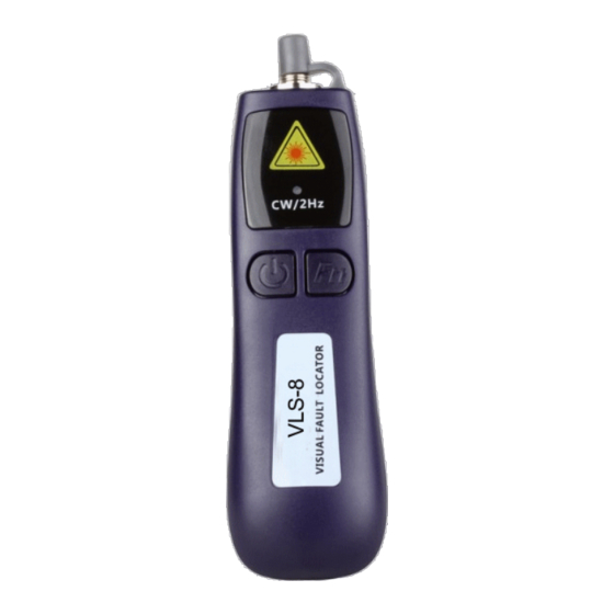
- Page 25 2 Brief description The visual red light source is used to screen optical fibres when troubleshooting and for fibre classification. The red light source allows individual optical fibres to be localised in bundles of fibres. Any light escaping from the fibre sheath due to crushing, broken fibres or at splices, and other occurrences, can be identified visually.
- Page 26 The 2 × AAA batteries inserted in the battery compartment on the rear supply the red light source with the energy required for approx. 5–6 hours in CW (constant mode). The operating time is significantly longer in pulse mode. After use or once the measurement is complete, ensure that the dust cap is put back onto the output to prevent contamination of the device.
- Page 27 2 × AAA batteries, slot on the bottom Dimensions 120 × 33 × 30 mm Net weight 70 g Standard accessories: Operating instructions DRAFT VERSION ASTRO Strobel Kommunikationssysteme GmbH Olefant 1–3 51427 Bergisch Gladbach Germany Phone: +49 2204 405-0 Fax: +49 2204 405-10 Web: astro-kom.de Email: kontakt@astro-kom.de...
- Page 28 Operating instructions Fibre optic microscope with 400× magnification DRAFT VERSION Fiber Scope user manual (release 1.0)
- Page 29 Contents Change history ........................2 Warning .......................... 3 Brief description......................5 Description of the device ..................6 Technical specifications ..................7 Change history Version Change history Date Name DRAFT VERSION Ed.1.0 Creation 28/04/2021 S. Mundinger Fiber Scope user manual (release 1.0)
- Page 30 ASTRO website (there may be a more recent version). The ASTRO company confirms that the information in this manual was correct at the time of printing, but it reserves the right to make changes to the specifications, the operation of the device and the operating manual without prior notice.
- Page 31 Recycling: Please recycle all packaging In accordance with the European Union (“EU”) Directive on Waste Electrical and Electronic Equipment (Directive 2002/96/EC) effective as of 13 August 2005, electrical and electronic equipment may no longer be disposed of as household waste. The manufacturer is obliged to accept the return of products like this once the end of their service life has been reached DRAFT VERSION...
- Page 32 2 Brief description The optical fibre microscope allows the connector surface of SC, SC or ST fibre optic connectors to be appraised. The layout of the internal optical lenses allows 400× magnification. Optical fibres with ferrules with a 2.5 mm diameter (SC, FC or ST) can be connected Both APC (8°) or UPC and PC (0°) connectors can be inserted If the optical fibre has been inserted into the front of the optical fibre microscope, then the end of the fibre can be focussed using the wheel.
- Page 33 2.1 Description of the device Connection for the optical fibre connector (2.5 mm ferrules) for Place the eyepiece against appraisal the eye Screw off for cleaning. Adjust to focus the lenses onto the end of the fibre for appraisal Battery compartment. To be fitted with 3 ×...
- Page 34 3 × AAA batteries, slot on the bottom Dimensions 220 × 55 × 40 mm Net weight 250 g Standard accessories: Operating instructions DRAFT VERSION ASTRO Strobel Kommunikationssysteme GmbH Olefant 1–3 51427 Bergisch Gladbach Germany Phone: +49 2204 405-0 Fax: +49 2204 405-10 Web: astro-kom.de Email: kontakt@astro-kom.de...
Need help?
Do you have a question about the FHS2 and is the answer not in the manual?
Questions and answers