Table of Contents
Advertisement
Quick Links
Advertisement
Table of Contents

Related Manuals for Omicron CMC 430


Summary of Contents for Omicron CMC 430
- Page 1 CMC 430 User Manual...
- Page 2 The user is responsible for every application that makes use of an OMICRON product. OMICRON electronics translates this manual from the source language English into a number of other languages. Any translation of this manual is done for local requirements, and in the event of a dispute between the English and a non-English version, the English version of this manual shall govern.
-
Page 3: Table Of Contents
Specification conditions ...................... 17 System clock accuracy ....................... 18 Synchronization ........................18 Current outputs ........................19 3.4.1 Protection ............................3.4.2 Accuracy ............................3.4.3 Total harmonic distortion and noise (THD+N) ..................3.4.4 Output power ............................. 3.4.5 Duty cycle ............................Voltage outputs ........................24 OMICRON... - Page 4 CMC 430 User Manual 3.5.1 Protection ............................3.5.2 Accuracy ............................3.5.3 Total harmonic distortion and noise (THD+N) ..................3.5.4 Output power ............................. Generator combination socket ................... 28 Simulated output power ...................... 29 AUX DC output ........................29 Binary outputs ........................30 3.10...
- Page 5 Contents Potential errors, possible causes, remedies ..............49 Overheating ........................49 Limited warranty ....................... 50 Open source license information ................... 51 Support ..........................52 OMICRON...
-
Page 6: About This Manual
CMC 430 test set hardware and its specifications. This manual is supplemented by the "Safe use of the CMC 430" manual, on-site safety regulations and existing national safety standards for accident prevention and environmental protection. -
Page 7: Device Overview
It allows full support of the IEC 61850 protocol for signal generation and measurement. All interfaces and indicators of the CMC 430 are positioned on the front plate. Therefore, the CMC 430 can be operated in different positions according to the specific requirements of the application environment. -
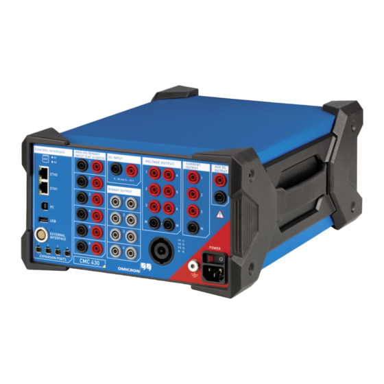
Page 8: Front Panel
CMC 430 User Manual Front panel This section provides an overview of the CMC 430 front panel elements. For detailed information about an element → sections to 2.11. DC INPUT CURRENT OUTPUT High-accuracy analog 3 x 12.5 A current outputs;... -
Page 9: Control Interface Section
Ethernet interfaces ETH1 and ETH2, and the accessory ports EXPANSION PORTS 1 ... 4. 2.2.1 Associate button ASC The CMC 430 can be remotely controlled via an Ethernet or Wi-Fi network. Such networks provide the possibility to connect more than just one CMC test set. -
Page 10: Ethernet Interfaces
38. 2.2.4 USB ports The PC port (USB type B) connects the CMC 430 to the USB port of the controlling computer. The USB port (USB type A) is currently used for the USB Wi-Fi adapter only. The USB Wi-Fi adapter is required for connecting the CMC 430 to a Wi-Fi network. -
Page 11: Analog/Binary Input Section
The four potential-free normally open relay contacts can switch AC or DC currents of up to 8 A. Technical data → Binary outputs on page 30. NOTICE Equipment damage possible. ► Observe the power limits stated in section Binary outputs on page 30 when switching DC currents. OMICRON... -
Page 12: Voltage Output Section
Six voltage outputs for voltages up to 150 V or 212 V The voltage outputs are galvanically separated from all other connections of the CMC 430. The two black N sockets are galvanically connected to each other. The voltage outputs are protected against short-circuit and overload conditions. -
Page 13: Current Output Section
Two ranges can be configured for the three current outputs: 1.25 A or 12.5 A. The current outputs are galvanically separated from all other connections of the CMC 430. The current outputs are protected against open-circuit and overload conditions. The current amplifier is additionally protected against overtemperature. -
Page 14: Aux Dc Output Section
The output AUX DC OUTPUT can be used to supply test objects with DC voltage. The output voltage can be configured to 12 ... 264 V in the CMC 430 Web Interface or the controlling software or device (accessing the Web Interface →... -
Page 15: Generator Combination Socket
The voltage outputs 1 ... 3 and the current outputs 1 ... 3 are also wired to the 8-pole generator combination socket. This socket is intended to simplify the connection of test objects to the CMC 430. Please refer to the descriptions of the voltage and current outputs in sections... -
Page 16: Beeper
If you reduce the voltage setting for the AUX DC OUTPUT from a high value of, for example 220 V, to a low value of, for example 24 V, and you have enabled the beeper in the CMC 430 Web Interface, you will hear an intermittent beep while the voltage reduces from the high to the low value. -
Page 17: Technical Data
Absolute 1- and 2-year specifications are absolute accuracy values met by at least 99 % of all CMC 430 test sets even at the end of the specified time period after delivery of new devices or factory calibration of used devices. →... -
Page 18: System Clock Accuracy
CMC 430 User Manual System clock accuracy All signals generated or measured by the CMC 430 refer to a common internal time base that is specified as follows: Characteristic Specification Clock performance Stratum 3 (ANSI/T1.101-1987) Frequency drift (over time) 24 hours <... -
Page 19: Current Outputs
The current outputs are protected against open-circuit and overload conditions. The current amplifier is additionally protected against overtemperature. NOTICE Equipment damage possible. Infeed of currents from external sources may damage the current outputs. Only in the non-operative state, the current outputs are protected by short-circuit relays against external infeed. OMICRON... -
Page 20: Accuracy
CMC 430 User Manual 3.4.2 Accuracy The specifications given in this section are valid for single-channel current output. When using the parallel output configuration (1 x 37.5 A), the errors of the individual channels have to be added. The phase and amplitude accuracy of the current amplifier depends on the connected burden. For higher burdens, the influence of the output impedance needs to be considered. -
Page 21: Total Harmonic Distortion And Noise (Thd+N)
0.5 A < 0.07 % 1.25 A < 0.07 % 12.5 A 55 Hz < 0.10 % < 0.05 % 12.5 A < 0.05 % Note: These values are also guaranteed between 10 Hz and 100 Hz by design. OMICRON... -
Page 22: Output Power
CMC 430 User Manual 3.4.4 Output power The output power specifications were tested under the following conditions: • Compliance voltage set to 100 % • Symmetrical conditions (0°, 120°, 240°) for 3-phase modes • Frequency 50/60 Hz • Resistive load •... -
Page 23: Duty Cycle
A duty cycle of 75 %, for example, means that the CMC 430 provides the specified current for 75 % of the time, and then requires the remaining 25 % of the time to cool down (example: 30 s on and 10 s off). -
Page 24: Voltage Outputs
CMC 430 User Manual Voltage outputs Characteristic Specification Ranges 0 ... 150 V Frequency range Frequency range 0 ... 1 kHz Transient playback & power quality signals 0 ... 3 kHz Configurations (AC) 6 x 150 V 1 x 300 V... -
Page 25: Accuracy
Note: If the test object evaluates AC and DC components, the offset needs to be considered in the RMS value. The offset is calculated from the DC specification with a set value of zero. This is negligible for voltages higher than 1 V. OMICRON... -
Page 26: Total Harmonic Distortion And Noise (Thd+N)
CMC 430 User Manual Phase accuracy The phase accuracy is specified for a load current of I < 150 mA. Reference Frequency Accuracy 24 hours 2 years 50/60 Hz 0.005° 0.01° 10 Hz ... 100 Hz 0.005° 0.02° 0.5° 100 Hz ... 3 kHz... -
Page 27: Output Power
By adjusting the supply voltage to the lowest possible setting, it is possible to minimize the power dissipation in the amplifier in order to increase the possible continuous output power. Continuous operation means that the CMC 430 is able to provide a specified voltage at a specified load for at least 30 minutes. -
Page 28: Generator Combination Socket
Generator combination socket The 8-pole generator combination socket is intended to simplify the connection of test objects to the CMC 430. The voltage outputs 1 ... 3 and the current outputs 1 ... 3 are wired to the generator combination socket. -
Page 29: Simulated Output Power
0.25 V Protection Short-circuit and overload protection. Protection against voltage amplifier overtemperature. Overload indication NOTICE Equipment damage possible. Infeed of voltages from external sources may damage the AUX DC output. The output is not disconnected during the non-operative state. OMICRON... -
Page 30: Binary Outputs
CMC 430 User Manual Binary outputs Characteristic Specification Number of binary outputs Max. AC loading = 300 V, I = 8 A, refer to load limit curve Max. DC loading = 300 V, I = 8 A, refer to load limit curve... -
Page 31: Measurement Concept
Measurement bandwidth 4 kHz @ f = 10 kHz with > 80 dB attenuation above 5 kHz 16 kHz @ f = 40 kHz with > 85 dB attenuation above 20 kHz Typical input impedance 1 MΩ || 170 pF OMICRON... - Page 32 CMC 430 User Manual 3.10.2.1 Magnitude accuracy Range Frequency Accuracy Temperature coefficient ±(% of reading + % of range) ±(% of reading + % of range)/°C beyond 23 °C ± 5 °C 24 hours 1 year 2 years 10 mV 0.02 + 0.72 0.10 + 0.85 0.15 + 0.85 0.0015 + 0.0500...
- Page 33 Current output frequency Typ. coupled RMS voltage 10 mV 1 kHz 30 µV 100 mV 1 kHz 30 µV 1 kHz 48 µV 10 V 1 kHz 120 µV 100 V 1 kHz 2.4 mV 600 V 1 kHz 10 mV OMICRON...
-
Page 34: Binary Input Mode
CMC 430 User Manual 3.10.3 Binary input mode Characteristic Specification Sampling frequency 10 kHz Time resolution 100 µs Max. measuring time Unlimited Deglitch time 0 … 500 ms (refer to Deglitching input signals on page 36) Debounce time 0 … 500 ms (refer to... - Page 35 AC input voltage to a pulsing DC voltage. The deglitch time has to be set appropriately depending on the threshold in order to avoid that the CMC 430 triggers on every half wave of the signal. The following settings are recommended and should work sensibly for sinusoidal 50 Hz and 60 Hz signals: •...
- Page 36 The debounce function is placed after the deglitch function described above. Both functions are realized by the firmware of the CMC 430 and are calculated in real time. The figure below illustrates the debounce function. On the right-hand side of the figure, the debounce time is too short.
-
Page 37: Dc Measurement Input
±(% of reading + % of range) ±(% of reading + % of range)/°C beyond 23 °C ± 5 °C 24 hours 1 year 2 years 20 mA 0.01 + 0.01 0.04 + 0.01 0.05 + 0.02 0.001 + 0.0003 1 mA OMICRON... -
Page 38: Communication Interfaces (Usb, Ethernet, Expansion Ports)
CMC 430 User Manual 3.12 Communication interfaces (USB, Ethernet, expansion ports) 3.12.1 Interfaces ETH1 and ETH2 Connector RJ-45 Link speed 10/100/1000 Mbit/s Power over Ethernet (PoE) IEEE 802.3af (15.4 W max.) IEEE 802.3at (30 W max.) Cable Cat 5e STP (Shielded Twisted Pair) or better... -
Page 39: Iec 61850 Protocols
Typical processing time (application to network or vice versa): < 1 ms VLAN support Selectable priority and VLAN-ID 3.12.4 Other communication protocols The integrated Web Interface can be accessed via HTTP with a typical web browser (for example, Microsoft Internet Explorer or Google Chrome). OMICRON... -
Page 40: External Interface
CMC 430 User Manual 3.13 External interface The SELV interface connector EXTERNAL INTERFACE holds four additional transistor binary outputs (binary outputs 11 ... 14). Unlike regular relay outputs, these outputs are bounce-free (small signals) and have minimal reaction time. In addition, two high-frequency counter inputs for up to 100 kHz are available for the testing of energy meters. -
Page 41: Counter Inputs 1 And 2
Connection C14 connector according to IEC 60320-1 Voltage (single phase) Nominal voltage 100 ... 240 V Operational range 85 ... 264 V Nominal current 10 A Frequency Nominal frequency 50/60 Hz Operational range 45 ... 65 Hz Overvoltage category OMICRON... -
Page 42: Environmental Conditions
NOTICE Equipment damage possible. ► Do not use the CMC 430 under conditions that may cause or caused condensation inside or on the outside of the CMC 430. Condensation may occur, for example, if the CMC 430 is moved from a cold car to a warm and/or humid environment. -
Page 43: How To Read The Specifications Stated In This Chapter
OMICRON defines one or more calibration intervals in the specifications. The specifications stated for the CMC 430 are dimensioned in a way that 99 % of all test sets meet the specifications at the end of the calibration interval, which corresponds to 2.6 standard deviations for a statistical normal distribution. - Page 44 For comparison: The permissible error for a temperature range of 23 °C ± 5 °C is 0.525 μA. 3.18.2.2 Higher ambient temperature (DC) When operating the CMC 430 at ambient temperatures beyond 23 °C ± 5 °C, the temperature coefficient has to be taken into account. Set value: I...
-
Page 45: Increasing The Output Power
Increasing the output power Increasing the output power The possible output current and output voltage of the CMC 430 can be increased by connecting amplifiers in parallel or in series. The following output configuration examples represent a selection of the possible configurations. For a complete list of possible configurations, please check the Hardware Configuration of the controlling software or device. -
Page 46: Expansion Mode
CMC 430 User Manual Expansion Mode In "Expansion Mode", one CMC 430 test set works as "master unit", a second CMC 430 test set works as a current amplifier for the "master unit". That second CMC 430 is the so-called "slave unit in Expansion Mode". - Page 47 1 x 12.5 A; 192 VA @ 8 A; 24 Vrms: You can reach an output magnitude of up to By connecting two current outputs in series, you 37.5 A (3 × 12.5 A) by connecting the three can double the available compliance voltage. current outputs in parallel. OMICRON...
-
Page 48: Troubleshooting
• Screenshots or the exact wording of possible error messages 6. If you contact the OMICRON Technical Support, have your computer and test set available and be prepared to repeat the steps that caused the problem. To speed up the support, please attach all available diagnostic log files or a system snapshot file. -
Page 49: Potential Errors, Possible Causes, Remedies
Troubleshooting Potential errors, possible causes, remedies Some potential disruptions that may occur while operating the CMC 430 are listed below. Try to eliminate them by applying the remedies proposed here. Error Possible causes Remedies Power switch does not light up There is no power to the test set. -
Page 50: Limited Warranty
CMC 430 User Manual Limited warranty OMICRON guarantees that the test set is working properly within the specifications stated in this manual at the time of calibration. OMICRON offers a free-of-charge repair and readjustment for equipment that fails or drifts beyond the specified values within the first 24 months after the first shipment of new products or within 6 months after repairs. -
Page 51: Open Source License Information
Open source license information Open source license information Parts of the CMC test set software are under OMICRON license, other parts are under open source software licenses. Both the open source license texts and the necessary source code are provided in the OMICRON Open Source Download Area at www.omicronenergy.com/opensource. -
Page 52: Support
+1 713 830-4660 or +1 800-OMICRON Asia-Pacific: +852 3767 5500 Europe / Middle East / Africa: +43 59495 4444 Additionally, you can find the OMICRON Service Center or OMICRON Sales Partner closest to you at www.omicronenergy.com → Contact. Customer Portal - Stay Informed www.omicronenergy.com/customer... - Page 53 ENU 1169 05 02...
Need help?
Do you have a question about the CMC 430 and is the answer not in the manual?
Questions and answers