Table of Contents
Advertisement
Quick Links
Advertisement
Table of Contents

Related Manuals for Omicron CMC 310


Summary of Contents for Omicron CMC 310
- Page 1 CMC 310 User Manual...
- Page 2 However, OMICRON does not assume responsibility for any inaccuracies which may be present. The user is responsible for every application that makes use of an OMICRON product. OMICRON translates this manual from the source language English into a number of other languages.
-
Page 3: Table Of Contents
Electrical insulation groups............37 OMICRON... - Page 4 CMC 310 User Manual Increasing the output power Current outputs..............38 Voltage outputs .
-
Page 5: Preface
Preface Preface The purpose of this User Manual is to familiarize users with the CMC 310 test set hardware and its specifications. This manual is supplemented by the Safe use of CMC test sets manual, on-site safety regulations and existing national safety standards for accident prevention and environmental protection. -
Page 6: Safety
Safety Designated use The CMC 310 is a test set controlled by the CMControl P software for the testing of protection relays, energy meters, SCADA systems and devices. ► Do not use CMC test sets in any other way than described in this document or in working environments that exceed the specifications given in section 4 "Technical data". - Page 7 Do not open CMC test sets or carry out any modifications, extensions, or adaptations. ► If CMC test sets seem to be functioning improperly, please contact OMICRON Support. ► Falling adapters or cables are a hazard. Test leads wired to tall test objects must be secured mechanically.
-
Page 8: Cleaning
CMC 310 User Manual Cleaning Cleaning procedure: 1. Switch off the power switch. 2. Unplug the power cable from the power outlet. 3. Clean the CMC test set with a cloth dampened with isopropanol alcohol. Changing the power fuse Proceed as follows to replace the power fuse on your CMC test set: 1. -
Page 9: Test Set Overview
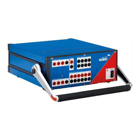
Test set overview Description The CMC 310 is a test set controlled by the CMControl P software. This User Manual describes the hardware of the CMC 310. The configuration and control of the CMC 310 is carried out by the CMControl P software. -
Page 10: Voltage Output
The 3 voltage outputs have a common neutral (N) that can be connected to protective earth, if required. → Section 4.4.3 "Voltage outputs" on page 25. The amplifier is galvanically separated from all other connectors of the CMC 310. All voltage outputs are protected against open circuits, L-N short circuits, overload, and overtemperature. -
Page 11: Current Output
► Make sure that there is no infeed from an external source. → Section 4.4.2 "Current outputs" on page 22. Each output is galvanically separated from all other connections of the CMC 310. All current outputs are protected against open circuits, short circuits, overload, and overtemperature. OMICRON... -
Page 12: Binary Input
3.2.3 BINARY INPUT All 6 inputs of the CMC 310 can be individually configured by the control software to be binary inputs (wet = potential-sensing or dry = potential-free). When the contacts are potential-sensing, the expected nominal voltage can be set for each binary input. -
Page 13: Aux Dc (Dc Power For Test Objects)
0 … 264 V in the control software or control device. ► Refer to the documentation of the control software for more information. The AUX DC output is galvanically separated from all other connections of the CMC 310. The output is protected against short-circuit, overload, and overtemperature. -
Page 14: Back Panel Connections
USB ports type A and B Safe use of CMC test sets manual). Fans for current and voltage outputs 1. The hardware for LL out 1–6 and ETH2 exists but is not used in the CMC 310. 3.3.1 USB ports USB port type A is used to insert USB peripherals such as wireless USB adapters. -
Page 15: Ethernet Port Eth1
If the Associate button is pressed while powering up the CMC test set, the IP configuration of the network interfaces is reset to factory default, which is DHCP/AutoIP for both network interfaces. This may be necessary to recover from settings with conflicting static IP addresses. OMICRON... -
Page 16: Status Led A And B
(N) that is internally connected to the protective earth (GND) of the housing. Note: The hardware for LL out 1–6 and ETH2 exists but is not used in the CMC 310. External interface (ext. Interf.): The SELV interface connector ext. - Page 17 Test set overview OMICRON...
-
Page 18: Technical Data
You can, for example, use a typical, often-used device under test as a reference, or use measurement equipment with a certified high accuracy. Should the test equipment fail, immediately contact OMICRON Support for calibration or repair. Do not try to use it anymore. -
Page 19: Main Power Supply
Operational limits in conjunction with a weak power supply input voltage In general, the maximum output power of the CMC 310 is limited by the power supply input voltage. If the power supply input voltage is less than 120 V , it is possible to supply the CMC 310 with 2 phases (L-L, for example with a NEMA 6 240 V U.S. -
Page 20: Operational Limits With Current And Voltage Amplifier In Parallel
1. t1 = maximum possible uptime for a cold CMC 310 test set. 2. At an ambient temperature of 23 °C, when operating the CMC 310 test set with a low power supply, allow a duty cycle of 10 min on/10 min off. -
Page 21: Outputs
1. For injections longer than 1 minute, the maximum fundamental frequency is limited to 587 Hz to comply with international trade restrictions for frequency-controlled signal generators. For other options, please contact OMICRON Support. 2. Amplitude derating for current outputs at frequencies above 380 Hz. -
Page 22: Current Outputs
8. For injections longer than 1 minute, the maximum fundamental frequency is limited to 587 Hz to comply with international trade restrictions for frequency-controlled signal generators. For other options, please contact OMICRON Support. 9. Amplitude derating at >380 Hz (→ "Current derating at high frequencies for sinusoidal signals" on page 23) - Page 23 Output current A Frequency in Hz Current derating at high frequencies for Typical compliance voltage (50/60 Hz) sinusoidal signals The low sensitive curves show the maximum available peak compliance voltage, which is mainly relevant for testing primary and electromechanical relays. OMICRON...
- Page 24 CMC 310 User Manual 1 × 64 A 3 × 32 A 3 × 32 A 1 × 64 A 1 × 32 A 1 × 32 A Current in A Current in A Current in A Current in A...
-
Page 25: Voltage Outputs
5. Values at 20 kHz measurement bandwidth, nominal value, and nominal load 6. For injections longer than 1 minute, the maximum fundamental frequency is limited to 587 Hz to comply with international trade restrictions for frequency-controlled signal generators. For other options, please contact OMICRON Support. OMICRON... -
Page 26: Low-Level Binary Outputs (Ext. Interf.)
CMC 310 User Manual Power diagram for 3-phase operation typical guaranteed Output voltage in V Power diagram for single-phase operation Section 5.2 "Voltage outputs" on page 39 Single-phase operation L-N Single-phase operation L-L typical typical guaranteed guaranteed Output voltage L-N in V Output voltage L-L in V 4.4.4... - Page 27 <3 µs (V = 5 V, R = 4.7 kΩ) extern pullup Connection Connector ext. Interf. (CMC 310 rear side) Insulation Reinforced insulation to all other potential groups of the test equipment. GND is connected to protective earth (PE). OMICRON...
-
Page 28: Binary Output Relays
For a manufacturer description about the connection sockets LL out and the external interface ext. Interf., visit the website www.lemo.com. You can order the LEMO cable directly from OMICRON. 4.4.5 Binary output relays 4 binary output relays (BINARY OUTPUT 1–4) Type Potential-free contacts;... -
Page 29: Dc Supply (Aux Dc)
Error <2 % Error <5 % Resolution <70 mV Connection 4 mm sockets on front panel. Short-circuit protection Overload indication Insulation Reinforced insulation from power supply and all SELV interfaces. 1. Percentage is with respect to each range’s full-scale. OMICRON... -
Page 30: Inputs
CMC 310 User Manual Inputs 4.5.1 Binary inputs General data of binary inputs 1…6 Number of binary inputs Trigger criteria Potential-free or DC-voltage compared to threshold voltage. Reaction time Max. 220 µs Sampling rate 10 kHz Time resolution 100 µs... - Page 31 The debounce function is placed after the deglitch function described above and both are realized by the firmware of the CMC 310 and are calculated in real time. The figure below illustrates the debounce function. On the right-hand side of the figure, the debounce time is too short.
-
Page 32: Counter Inputs 100 Khz (Low Level)
Rise and fall times <1 ms Maximum input voltage ±30 V Connection Socket ext. Interf. (rear side of CMC 310) Insulation Reinforced insulation to all other potential groups of the test equipment. GND is connected to protective earth (PE). OMICRON... - Page 33 Connector for one-guide notch and pull relief (for ext. Interf.). FGG.2B.316.CLAD 72Z Black anti-bend cable cover. GMA.2B.070 DN For a manufacturer description about the connection sockets LL out 1–6 and external interface ext. Interf., visit the website www.lemo.com. You can order the LEMO cable directly from OMICRON. OMICRON...
-
Page 34: Technical Data Of The Communication Ports
CMC 310 User Manual Technical data of the communication ports 4.6.1 NET-2 board The NET-2 board requires CMControl software version 2.30 (or later). × NET-2: 2 USB port and Ethernet ports ETH1/ETH2 USB type USB 2.0 high speed up to 480 Mbit/s... -
Page 35: Net-1C Board (Legacy Board)
5 … 95 % relative humidity; no condensation Climate Tested according to IEC 60068-2-78 Shock and vibration Vibration Tested according to IEC 60068-2-6; frequency range 10 ... 150 Hz; 2 g (20 sweeps) Shock Tested according to IEC 60068-2-27; 15 g/11 ms, half-sinusoid, each axis OMICRON... -
Page 36: Mechanical Data
CMC 310 User Manual Mechanical data Size, weight and protection Weight 13.1 kg (28.9 lb) Dimensions W × H × D 343 × 145 × 390 mm (13.5 × 5.7 × 15.4") (without handle) Housing IP20 according to IEC 60529... -
Page 37: Electrical Insulation Groups
BINARY INPUT 1/2 BINARY INPUT 3/4 2 x Ethernet 2 x USB LL out BINARY INPUT 5/6 Ext. Interf. BINARY OUTPUT 1 (Relay) BINARY OUTPUT 2 (Relay) BINARY OUTPUT 3 (Relay) BINARY OUTPUT 4 (Relay) Insulation designed for pollution degree 2. OMICRON... -
Page 38: Increasing The Output Power
For a complete list of possible configurations, check the hardware configuration of the control software or control device. When using the CMC 310 in an operational mode that parallels the output currents, make sure to use test leads of an appropriate diameter. -
Page 39: Voltage Outputs
Increasing the output power Voltage outputs 1 × 0 ... 300 V 1 × 0 ... 600 V VOLTAGE OUTPUT VOLTAGE OUTPUT Typical: 275 VA at 200 ... 600 V. Typical: 200 VA at 100 ... 300 V. OMICRON... -
Page 40: Troubleshooting
Troubleshooting Troubleshooting guide In case of operational problems with the CMC 310, and if you could not find a solution in this manual or the other accompanying documentation (of control software and device), proceed as follows: 1. Check whether the malfunction is reproducible and document it. -
Page 41: Potential Errors, Possible Causes, Remedies
Troubleshooting Potential errors, possible causes, remedies Some potential disruptions that may occur while operating the CMC 310 are listed below. Try to eliminate them by applying the remedies proposed here. Error Possible causes Remedies The power switch does not light There is no power to the test set. - Page 42 CMC 310 User Manual OMICRON...
-
Page 43: Support
OMICRON Academy – learn more www.omicronenergy.com/academy Learn more about your product in one of the training courses offered by the OMICRON Academy. OMICRON electronics GmbH, Oberes Ried 1, 6833 Klaus, Austria, +43 59495 OMICRON... - Page 44 ENU 1012 05 01...
Need help?
Do you have a question about the CMC 310 and is the answer not in the manual?
Questions and answers