
Related Manuals for Vortice TAL


Summary of Contents for Vortice TAL
- Page 1 Libretto istruzioni Instructions Booklet Auto Auto COD. 5.571.084.151 12/12/2018...
-
Page 2: Table Of Contents
Safety ........36 Vortice cannot assume any responsibility for damage 1. -
Page 3: Sicurezza
• Dopo aver tolto il prodotto dal suo imballo, assicurarsi della sua integrità: nel dubbio rivolgersi a persona professionalmente qualificata o ad un Centro Assistenza Tecnica autorizzato Vortice. • Non lasciare parti dell’imballo alla portata di bambini o persone diversamente abili. - Page 4 Vortice. • In caso di cattivo funzionamento e/o guasto dell'apparecchio, rivolgersi subito ad un Centro Assistenza Tecnica autorizzato Vortice e richiedere, per l’eventuale riparazione, l'uso di ricambi originali Vortice. • Se il prodotto cade o riceve forti colpi farlo verificare subito presso un Centro di Assistenza Tecnica autorizzato Vortice.
-
Page 5: Descrizione Ed Impiego
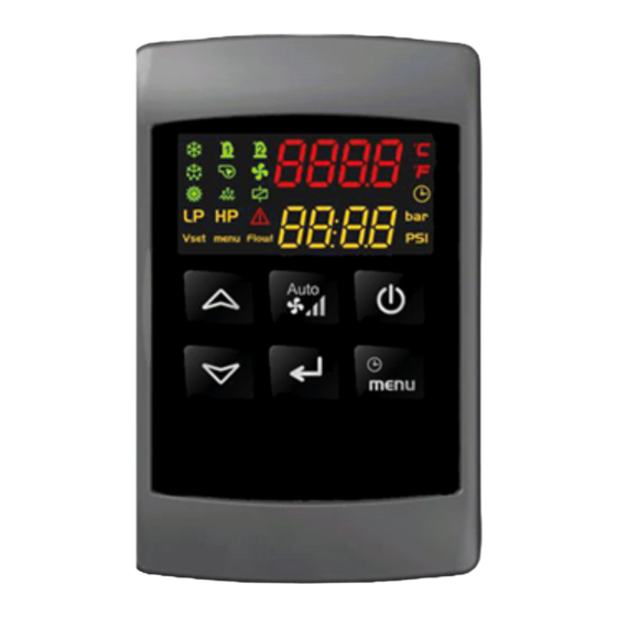
ITALIANO 1. Descrizione ed impiego TAL è un pannello di comando remoto compatibile con scatola ad incasso di tipo 503. 2. Interfaccia utente Tasti TASTO FUNZIONE Consente di accendere e spegnere la macchina All’interno dei menù consente di scorrere le voci visualizzate. - Page 6 ITALIANO Pressione contemporanea dei tasti per 3 secondi: consente l’accesso alla programmazione dei parametri Pressione contemporanea dei tasti: consente l’uscita dalla programmazione parametri °C -°F Accese quando i display visualizzano temperatura o pressione Accesa quando il display inferiore visualizza l’ora oppure un parametro di impostazione dell’ora del set point ridotto.
- Page 7 ITALIANO Personalizzazione display Tramite un’opportuna configurazione dei parametri contenuti nella famiglia dP (display) è possibile personalizzare in base alle proprie necessità la visualizzazione del display durante il funzionamento; nel display inferiore e superiore dello strumento e del terminale remoto possono essere visualizzate le temperature, oppure lo stato della macchina, oppure l’orologio.
- Page 8 ITALIANO 3. Caratteristiche ingressi e uscite Configurabilità OUT Configurabilità OUT Configurabilità ING. Configurabilità IN DIGITALI ANALOGICI DIGITALI ID1..ID11 ANALOGICI Pb1..Pb6 RL1..RL8 OUT1..OUT4 Non utilizzato Non utilizzato Non utilizzato Non utilizzato Sonda aria di ripresa da Velocità 1 ventilatore Ventilatore ON / OFF remoto ambiente/interno immissione/rinnovo immissione/rinnovo...
-
Page 9: Prima Installazione
ITALIANO Ingressi digitali • ON/OFF REMOTO Consente di accendere o spegnere la macchina da remoto • VELOCITÀ 1 Consente di selezionare la velocità 1 dei ventilatori di immissione/rinnovo ed espulsione • VELOCITÀ 2 Consente di selezionare la velocità 2 dei ventilatori di immissione/rinnovo ed espulsione •... - Page 10 ITALIANO Come Memorizzare I Parametri Dello Strumento Sulla “Hot Key” (Upload) A strumento acceso: 1. Inserire la chiavetta. 2. Entrare in menu funzioni “menu” 3. Selezionare la funzione UPL sul display inferiore 4. Premere invio Inizia lo scarico dei dati dallo strumento alla chiavetta. Durante questa fase sul display inferiore viene visualizzato il messaggio “UPL”...
- Page 11 ITALIANO Come cambiare il valore di un parametro Entrare In Programmazione 1. Premere contemporaneamente il tasti Invio + DOWN per 3 sec 2. Selezionare il parametro desiderato 3. Premere il tasto Invio per abilitare la modifica del valore 4. Modificare il valore con i tasti UP o DOWN 5.
- Page 12 ITALIANO COME ENTRARE IN PROGRAMMAZIONE NEL LIVELLO PR1 Per entrare nel menù parametri al livello Pr1 “utente”: 1. Premere contemporaneamente il tasti INVIO + DOWN per 3 sec.; il display superiore visualizza la label PAS, il display inferiore label Pr1 2.
- Page 13 ITALIANO COME ENTRARE IN PROGRAMMAZIONE NEL LIVELLO PR2 Per entrare nel menù parametri al livello Pr2 “assistenza”: 1. Premere contemporaneamente i tasti INVIO + DOWN per 3 sec.; il display superiore visualizza la label PAS, il display inferiore label Pr1. 2.
- Page 14 ITALIANO Se il led n° 4 lampeggia significa che il parametro visualizzato è visibile e non modificabile in Pr2. Se il led n° 3 e il led n° 4 lampeggiano significa che il parametro visualizzato è visibile e non modificabile in Pr2 e in Pr1.
-
Page 15: Menu Funzioni (Tasto Menu)
ITALIANO COME RENDERE NUOVAMENTE VISIBILE E MODIFICABILE UN PARAMETRO A LIVELLO Pr1 / Pr2 1. Tenere premuto il tasto INVIO 2. Premere e rilasciare il tasto MENU i led n° 3 / 4 diventano accesi fissi il parametro ridiventa visibile e modificabile Visualizzazione In Programmazione Della Polarità... - Page 16 ITALIANO COME VISUALIZZARE LO STATO DI UN ALLARME ED EFFETTUARE IL RESET FUNZIONE ALRM ENTRARE IN MENU FUNZIONI 1. Con i tasti UP o DOWN selezionare la funzione ALrM 2. Premere il tasto invio (se non è presente nessun allarme la pressione del tasto invio non è abilitata) 3.
-
Page 17: Selezione-Abilitazione Del Modo Di
ITALIANO COME ESPORTARE LA MAPPA PARAMETRI NELLA HOTKEY MENU UPL La procedura per l’esportazione della mappa parametri nella Hot Key è la seguente: 1) inserire la HotKey nel connettore 5 vie posto nel retro dello strumento 2) premere il tasto invio 3) la scritta UPL lampeggia 4) la scritta End segnala il termine dell’operazione VISUALIZZAZIONE A DISPLAY DELLA PERCENTUALE DI LAVORO DELLE USCITE PROPORZIONALI PER IL... -
Page 18: Regolazione
ITALIANO 8. Regolazione FUNZIONAMENTO VENTILATORI I ventilatori di immissione/rinnovo e di espulsione possono essere configurati nel seguente modo: • funzionamento a 3 velocità su uscite relè: devono essere configurati tre relè per ogni ventilatore (velocità 1, velocità 2, velocità 3) •... - Page 19 ITALIANO FUNZIONE FREE COOLING La funzione di free cooling è attiva se la macchina è accesa nel modo raffrescamento; in funzionamento invernale ed in STD-BY oppure OFF l’uscita digitale configurata come serranda free-cooling sarà sempre in OFF. La gestione della serranda di free coling avviene come descritto di seguito: •...
- Page 20 ITALIANO FUNZIONAMENTO A FASCE ORARIE Tramite abilitazione e l’impostazione di fascie orarie è possibile accendere/spegnere il controllore e abilitare il set point ridotto, ovvero forzare le ventole alla velocità 1; il controllore dovrà necessariamente avere l’orologio a bordo. La richiesta di set point ridotto è attiva: •...
- Page 21 ITALIANO ESEMPIO FUNZIONAMENTO GIORNALIERO 1. Selezionare il parametro desiderato; il display superiore visualizza 0 - 0 2. Premere il tasto invio, il display superiore visualizza “0 – 0” lampeggiante 3. Tramite i tasti UP o DOWN impostare il valore desiderato in base alla tabella di configurazione illustrata sopra 4.
-
Page 22: Tastiera Remota
ITALIANO ALLARME FILTRI Se il controllore è in modalità raffrescamento oppure riscaldamento (quindi non in OFF o STD-BY) è attivo il conteggio per la segnalazione dell’allarme filtri; un parametro consente l’impostazione della soglia di ore di funzionamento per la segnalazione dell’allarme (St15). Un parametro consente di decidere se l’allarme è... - Page 23 ITALIANO Sonda in allarme Azione dell’allarme. Disabilitazione del Free Cooling; il resto delle regolazioni funziona Sonda ripresa ambiente regolarmente. Sonda mandata ambiente Nessuna azione sulle regolazioni. Disabilitazione del Free Cooling e della funzione di Energy Saving se abilitata Sonda aria esterna da fascie orarie;...
- Page 24 ITALIANO Significato label display Atr1 / Atr2 allarme comunicazione con tastiera remota Causa attivazione Tastiera remota abilitata ma non comunica con display a bordo macchina Automatico a seguito di risoluzione del problema (controllo connessioni, controllo Reset cablaggio, sostituzione della tastiera o del controllore) Icona lampeggiante + label “Atr1”...
-
Page 25: Parametri
ITALIANO 11. Parametri REGOLATORE Parametro Descrizione Risoluzione -50.0 70.0 °C Set point selezione estate / inverno °F 25.0 °C Differenziale selezione estate / inverno °F 25.0 °C Dt per ingresso in free cooling °F 25.0 °C Differenziale uscita free cooling °F Soglia temperatura minima per -50.0... - Page 26 3 1= visualizza le grandezze definite da par. dP1 e dP2 2= visualizza la label “OFF” Default visualizzazione display superiore del terminale remoto TAL n° 1 0= la visualizzazione dipende dal valore dei parametri dP 4 dP01 – dP02 1= il display superiore visualizza la temperatura misurata dalla sonda NTC a bordo del terminale remoto n°...
- Page 27 ITALIANO Default visualizzazione display superiore del terminale remoto TAL n° 2 dP 5 0= la visualizzazione dipende dal valore dei parametri dP01 – dP02 1= il display superiore visualizza la temperatura misurata dalla sonda NTC a bordo del terminale remoto n° 2...
- Page 28 ITALIANO CONFIGURAZIONE Parametro Descrizione udm Risoluzione CF21 Configurazione ID8 CF22 Configurazione ID9 CF23 Configurazione ID10 CF24 Configurazione ID11 CF25 Configurazione RL1 CF26 Configurazione RL2 CF27 Configurazione RL3 CF28 Configurazione RL4 CF29 Configurazione RL5 CF30 Configurazione RL6 CF31 Configurazione RL7 CF32 Configurazione RL8 Configurazione uscita OUT 1 0=uscita disabilitata...
- Page 29 0= assente CF46 1= sonda NTC a bordo 2= senza sonda NTC a bordo °C -12.0 12,0 CF47 Offset sonda NTC terminale remoto n° 1 TAL °F -12.0 12,0 °C CF48 Offset sonda NTC terminale remoto n° 2 TAL °F...
- Page 30 ITALIANO ENERGY SAVING Parametro Descrizione Risoluzione Inizio fascia di funzionamento n ° 1 (0÷24) 24.00 10 Min ES 2 Fine fascia di funzionamento n ° 1 (0÷24) 24.00 10 Min ES 3 Inizio fascia di funzionamento n ° 2 (0÷24) 24.00 10 Min ES 4...
-
Page 31: Variabili Per Interfaccia Visiograph
ITALIANO 12. Variabili per interfaccia Visiograph STATI Sonde di temperatura (STATO LETTURA) Ingressi digitali (STATO LETTURA) Uscite digitali (STATO LETTURA) Uscite Analogiche (STATO LETTURA) Modo di funzionamento ESTATE / INVERNO Stato unità ON / OFF Stato Bypass-Free Cooling Stato Antigelo Stato Ventilatore Rinnovo (Vel 1-2-3) Stato Ventilatore Espulsione (Vel 1-2-3) Stato Ventilatore Rinnovo (%) -
Page 32: Schemi Di Collegamento
21 - 24 Funzione Booster Contatto chiuso / funzione attiva 22 - 24 Funzionamento Silenzioso Contatto chiuso / funzione attiva Alimentazione filtro 4 – 8 Uscita in tensione (220v) elettronico 25 – 27 Connessione display (TAL) non invertire la polarità... -
Page 33: Mancanza Di Tensione
4. Se è presente un allarme a riarmo manuale viene mantenuto lo stato di allarme fino al ripristino da tasto. 15. Installazione e montaggio Dime Di Foratura Terminale Remoto TAL Il terminale remoto può essere montato a pannello, su foro 72x56 mm, e fissato con viti o incassato all’interno di una scatola di tipo 503 incassata nel muro in verticale. -
Page 34: Collegamenti Elettrici
ITALIANO 16. Collegamenti elettrici • Morsettiere sconnettibili (MOLEX MICROFIT) a 18 e 14 vie per l’alimentazione, la connessione degli ingressi digitali, degli ingressi analogici, delle uscite analogiche, della tastiera remota. • Morsettiera sconnettibile (AMP) 12 vie per la connessione delle uscite relè. •... -
Page 35: Smaltimento
ITALIANO SMALTIMENTO IN ALCUNI PAESI DELL'UNIONE EUROPEA QUESTO PRODOTTO NON RICADE NEL CAMPO DI APPLICAZIONE DELLA LEGGE NAZIONALE DI RECEPIMENTO DELLA DIRETTIVA RAEE E QUINDI NON È IN ESSI VIGENTE ALCUN OBBLIGO DI RACCOLTA DIFFERENZIATA A FINE VITA. Attenzione Questo prodotto è conforme alla Direttiva EU 2012/19/EC. Il simbolo del cassonetto barrato riportato sull’apparecchio indica che il prodotto, alla fine della propria vita utile, dovendo essere trattato separatamente dai rifiuti domestici, deve essere conferito in un centro di raccolta differenziata per apparecchiature elettriche ed elettroniche oppure riconsegnato al rivenditore al momento... -
Page 36: Safety
• Do not use the device for any function other than that specified in this booklet. • After removing the product from its packaging, ensure that it is not damaged. If in doubt please contact a professionally qualified person or authorised Vortice Technical Assistance Centre. - Page 37 Vortice Technical Assistance Centre. • Promptly contact an authorised Vortice Technical Assistance Centre in the event of unit malfunction and/or failure and request the use of original Vortice spare parts for any repairs. • If the product falls or receives a strong blow, immediately have it inspected at an authorised Vortice Technical Assistance Centre.
-
Page 38: Description And Use
ENGLISH 1. Description and use TAL is a remote control panel compatible with 503 type recessed box. 2. User interface Tasti TASTO FUNZIONE It turns the machine on and off Within the menus it allows to scroll through the displayed items. In the “parameter” menu it allows to scroll the parameters changing their value. - Page 39 ENGLISH By pressing the keys simultaneously for 3 seconds, it allows access to parameter programming Simultaneous pressure of the keys: it allows the exit from the parameter programming °C -°F ON when a temperature or pressure is visualized It is turned on when the lower display shows the time or a setting parameter of the reduced set point time.
- Page 40 ENGLISH Display customization Through an appropriate configuration of the parameters contained in the dP (display) family, it is possible to customize the configuration of the display during operation; in the lower and upper display of remote terminal the temperatures, or the status of the machine, or the clock can be displayed Parameter dP01 Visualization of upper display 0 =Not displayed 1 =Air temperature (internal to extract)
-
Page 41: Input/Output Configuration
Relay SPDT 5(3) A 250Vac Analogic output OUT1..OUT4 Configurable function; 0..10V Output used for connection to Hot Output Hot Key / TTL Key or personal computer via external Prog Tool module Output used for connection to TAL Keyboard output keyboard or Visograph... -
Page 42: First Installation
ENGLISH Digital inputs • ON/OFF REMOTE It allows to turn the recovery unit on or off remotely • SPEED 1 It allows to select the speed 1 of the input/renewal and exhaust fans • SPEED 2 It allows to select the speed 2 of the input/renewal and exhaust fans •... - Page 43 ENGLISH How to memorize the parameters of the controller on the “Hot Key” (Upload) With the instrument switched on: 1. Insert the key. 2. Enter in the menu function 3. Select the UPL function on the lower display 4. Press the “enter” key. It starts the download of the data from the controller to the USB. During this phase on the lower display it is visualized the text “UPL”...
- Page 44 ENGLISH How to change the value of a parameter Enter Programming 1. Press the Enter + DOWN keys simultaneously for 3 sec 2. Select the desired parameter 3. Press the Enter key to enable the value change 4. Change the value with the UP or DOWN keys 5.
- Page 45 ENGLISH HOW TO ENTER IN PROGRAMMING IN LEVEL PR1 To enter in the parameter menu at the "user" level Pr1: 1. Press the ENTER + DOWN keys simultaneously for 3 seconds; the upper display shows the PAS label, the lower display label Pr1 2.
- Page 46 ENGLISH HOW TO ENTER IN PROGRAMMING IN LEVEL PR2 To enter in the parameter menu at the Pr2 "assistance" level: 1. Press the ENTER + DOWN keys simultaneously for 3 seconds; the upper display shows the PAS label, the lower display shows label Pr1. 2.
- Page 47 ENGLISH If LED n° 4 flashes it means that the parameter displayed is visible and it can not be modified in Pr2. If LED n° 3 and LED n ° 4 flash, this means that the parameter displayed is visible and it can not be modified in Pr2 and Pr1.
-
Page 48: Funtion Menu
ENGLISH HOW TO MAKE VISIBLE AND MODIFIABLE AGAING A PARAMETER AT LEVEL Pr1 / Pr2 1. Push and hold the ENTER key 2. Push and release the MENU key. Leds n ° 3/4 become steady on and the parameter becomes visible and modifiable Visualization in Programming of the Polarity of Digital Inputs / Outputs Parameters that allow you to configure:... - Page 49 ENGLISH HOW TO DISPLAY THE STATUS OF AN ALARM AND PERFORM THE RESET ALRM FUNCTION ENTER THE FUNCTION MENU 1. Use the UP or DOWN keys to select the ALrM function 2. Press the enter key (if there is no alarm, pressing the enter key is not enabled) 3.
-
Page 50: Selection - Enabiling Of The Operating Mode
ENGLISH HOW TO EXPORT THE PARAMETERS MAP IN THE HOTKEY UPL MENU The procedure for exporting the parameter map in the hot key is as follows: 1) insert the HotKey into the 5-way connector on the back of the instrument 2) press the “enter”... -
Page 51: Regulation
ENGLISH 8. Regulation FANS OPERATION The input / renewal and exhaust fans can be configured as follows: • 3-speed operation on relay outputs: three relays must be configured for each fan (speed 1, speed 2, speed 3) • 3-speed operation on analog outputs: a relay (speed 1) + one must be configured analogue output for each fan (relay for enabling and analog output for regulation of the speed) The fan speed is controlled manually by the keyboard or by digital inputs;... - Page 52 ENGLISH Operating status Heating Cooling Outdoor air temperature FREE COOLING FUNCTION The free cooling function is active if the machine is switched on in cooling mode. In operation in winter and in STD- BY or OFF the digital output configured as a free-cooling damper will always be in OFF mode. The management of the free coling damper takes place as described below: if the temperature measured by the room temperature sensor - outdoor air temperature ≥...
- Page 53 ENGLISH TIME BANDS OPERATION By enabling and setting time bands it is possible to switch the controller on / off and enable the reduced set point, i.e. force the fans at speed 1; the controller must necessarily have the watch on board. The reduced set point request is active: •...
- Page 54 ENGLISH EXAMPLE OF A DAILY PROGRAMMING 1. Select the desired parameter, the upper display shows 0 - 0. 2. Press the enter key, the upper display shows "0 - 0" flashing. 3. Use the UP or DOWN keys to set the desired value according to the configuration table shown above. 4.
-
Page 55: Remote Keyboard
ENGLISH FILTERS ALARM If the controller is in cooling or heating mode (i.e. not in the OFF or STD-BY mode), the count for the filter alarm signal is active, a parameter allows setting the operating hours threshold for alarm signaling (St15). A parameter allows to decide whether the alarm is signaling only, if it immediately blocks the machine or if it blocks it with selectable delay (St16): •... - Page 56 ENGLISH Probe in alarm Alarm action. Ambient recovery probe Disabling Free Cooling, the rest of the regulations work regularly. Room delivery probe No action on regulations Disabling Free Cooling and the Energy Saving function if enabled by time External air probe bands;...
- Page 57 ENGLISH Meaning label Atr1 / Atr2 communication alarm with remote keyboard display Reason Remote keyboard enabled but it does not communicate with the machine display Automatic after problem resolution (connection control, wiring control, keyboard Reset or controller replacement) Symbol blinking + label “Atr1” o “Atr2” Action None Alarm history...
-
Page 58: Parameters
ENGLISH 11. Parameters REGULATOR Parameter Description Resolution -50.0 70.0 °C Summer / winter set point selection °F 25.0 °C Differential summer / winter selection °F 25.0 °C Dt for entry in free cooling °F 25.0 °C Differential free cooling outlet °F Minimum temperature threshold for free -50.0... - Page 59 0= it visualizes label "STD-BY" 1= it visualizes values defined from par. dP1 and dP2 2= it visualizes label “OFF” Default display of the upper display of the TAL remote terminal n° 1 0 = the display depends on the value of the parameters...
- Page 60 ENGLISH Default display of the upper display of the remote terminal TAL n° 2 dP 5 0 = the display depends on the value of the parameters dP01 - dP02 1 = the upper display shows the temperature measured by the NTC probe on the remote terminal n° 2...
- Page 61 ENGLISH CONFIGURATION Parameter Description udm Resolution CF21 Configuration ID8 CF22 Configuration ID9 CF23 Configuration ID10 CF24 Configuration ID11 CF25 Configuration RL1 CF26 Configuration RL2 CF27 Configuration RL3 CF28 Configuration RL4 CF29 Configuration RL5 CF30 Configuration RL6 CF31 Configuration RL7 CF32 Configuration RL8 Output configuration OUT 1 0= output disabled...
- Page 62 -12.0 12,0 CF47 Remote terminal NTC probe offset n°1 TAL °F -12.0 12,0 °C CF48 Remote terminal NTC probe offset n° 2 TAL °F CF49 Presence of the Visograph keyboard 0= cooling / heating CF50 1= cooling / heating Operation selection in cooling o...
- Page 63 ENGLISH ENERGY SAVING Parameter Description Resolution Operating band start n ° 1 (0÷24) 24.00 10 Min ES 2 End of operation band n ° 1 (0÷24) 24.00 10 Min ES 3 Operating band start n ° 2 (0÷24) 24.00 10 Min ES 4 End of operation band n °...
-
Page 64: Variables For The Visiograph Interface
ENGLISH 12. Variables for the Visiograph interface STATUS Temperature probes (READING STATUS) Digital inputs (READING STATUS) Digital outputs (READING STATUS) Analog outputs (READING STATUS) Operating mode SUMMER/WINTER Unit status ON / OFF Bypass-Free Cooling status Anti-freeze status Renewal Fan Status (Vel 1-2-3) Exhaust fan state (Vel 1-2-3) Inlet fan state (%) Exhaust fan state (%) -
Page 65: Wiring Diagrams
21 - 24 Booster function Closed contact / active function 22 - 24 Silent operation Cloed contact / active function 4 – 8 Electronic filter supply Voltage output (220V) 25 – 27 Connection display (TAL) do not invert polarity... -
Page 66: Voltage Free Event
4. If a manual reset alarm is present, the alarm status is maintained until the reset by key. 15. Installation and assembly Drilling dime TAL Remote terminal The remote terminal can be mounted on a panel, on a 72x56 mm hole, and fixed with screws or recessed inside box type 503 built into the vertical wall. -
Page 67: Electrical Connections
ENGLISH 16. Electrical connections • 18 and 14-way disconnectable terminal blocks (MOLEX MICROFIT) for power supply, connection of digital inputs, analog inputs, analog outputs, remote keypad. • 12-way disconnectable terminal block (AMP) for connecting relay outputs. • Five-pin connector (TTL output) for connection to Prog Tool or Hot Key The cross-section of the 18 and 14-way terminal blocks (MOLEX) is AWG 24 except for the power cables that are AWG 22. -
Page 68: Disposal
Vortice E lettros ociali S .p.A. res erves the right to make improvements to products at any time and without prior notice. La s ociété Vortice E lettros ociali S .p.A. s e rés erve le droit d'apporter toutes les variations afin d'améliorer s es produits en cours de commercialis ation.
Need help?
Do you have a question about the TAL and is the answer not in the manual?
Questions and answers