Advertisement
Quick Links
NC2011-NC2051 Network Boards Installation
Sheet
EN CS FR HU LT NL PL PT RO TR
1
3
EN: Installation Sheet
Description
The NC2011 and NC2051 Network Board interfaces fire panels
and repeater/emulators in the FP1200/FP2000 Series. They
are used with the network interface modules NE2011 (RS-485
electrical) or NE2051 (optical).
Caution:
For general guidelines on system planning, design,
installation, commissioning, use, and maintenance, refer to the
EN 54-14 standard and local regulations.
Installation
WARNING:
Electrocution hazard. To avoid personal injury or
death from electrocution, remove all sources of power and
allow stored energy to discharge before installing or removing
equipment.
© 2022 Carrier. All rights reserved.
2
The interface board must always be positioned below the host
board (FC2012) located on the inside of the panel or repeater
door.
Mount the interface board. If the panel is fitted with a bus
termination card, plug it into the interface board when
installation of boards is complete. Connect the NE2011 (RS-
485 electrical) or NE2051 (optical) as shown in Figure
2
Figure
. If signals must repeat from one NE2011 module to
another, set jumper J1 to turn repeat mode ON. See Figure 3
and Table 1 for settings.
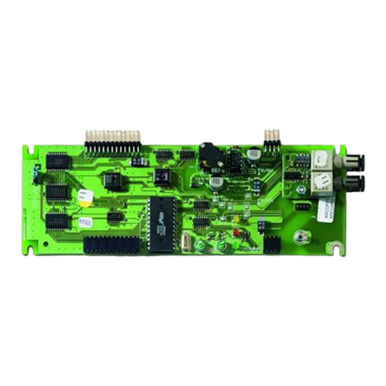
Figure 1 shows connections for the NC2011.
1.
Termination jumper
2.
Shield
3.
Earth jumper
Figure 2 shows connections for the NC2051.
If signals must repeat from one NC2011 module to another, set
jumper J1 to turn repeat mode ON. See Figure 3 and Table 1
for settings.
1 / 12
P/N 10-4109-501-1N01-03 • ISS 21JUN22
1
and
Advertisement

Subscribe to Our Youtube Channel
Related Manuals for Aritech NC2011


Summary of Contents for Aritech NC2011
- Page 1 Earth jumper Installation Figure 2 shows connections for the NC2051. If signals must repeat from one NC2011 module to another, set WARNING: Electrocution hazard. To avoid personal injury or jumper J1 to turn repeat mode ON. See Figure 3 and Table 1 death from electrocution, remove all sources of power and for settings.
-
Page 2: Specifications
Zemnicí propojka documentation, visit firesecurityproducts.com. Na obrázku 2 jsou uvedena připojení modulu NC2051. Pokud se signály musí opakovat z jednoho modulu NC2011 na Product warnings and disclaimers druhý na téže síťové desce, nastavte propojku J1, aby se ZAPNUL režim opakování. Nastavení naleznete na obrázku 3 THESE PRODUCTS ARE INTENDED FOR SALE TO AND a v tabulce 1. -
Page 3: Installation
NC2051 35 mA Rozměry (Š × V) 190 × 64 mm Les cartes NC2011 et NC2051 sont des interface réseau pour Hmotnost 85 g les centrales de détection incendie ou répéteur de la série FP1200/FP2000. Ces cartes sont utilisées avec les modules Teplota d'interface réseau NE2011 (RS-485 paire cuivrée) ou NE2051... -
Page 4: Spécifications
INSTALLATION DE FAÇON APPROPRIÉE. A 2. ábrán láthatók az NC2051 csatlakozásai. Pour obtenir des informations supplémentaires Ha a jeleket ismételni kell az egyik NC2011 modulról egy sur les garanties et la sécurité, rendez-vous à másikra, állítsa a J1 jumpert ON állásba a jelismétlés l’adresse https://firesecurityproducts.com/... - Page 5 2 pav. parodytos NC2051 jungtys. BIZTOSÍTANI, HOGY A TERMÉKEIT MEGVÁSÁROLÓ TERMÉSZETES VAGY JOGI SZEMÉLY, BELEÉRTVE A Jeigu signalai turi kartotis iš vieno NC2011 modulio kitame, „HIVATALOS FORGALMAZÓT” ÉS A „HIVATALOS nustatykite trumpiklį J1, kad įjungtų kartojimo režimą. Dėl VISZONTELADÓT”, MEGFELELŐEN KÉPZETT, ILLETVE nustatymo žr.
- Page 6 SPECIALISTAMS IR JUOS MONTUOTI GALI TAIP PAT TIK afbeelding 3 en tabel 1 voor instellingen. KVALIFIKUOTAS SPECIALISTAS. In afbeelding 1 ziet u de aansluitingen voor de NC2011. „CARRIER FIRE & SECURITY B.V.“ NEGALI UŽTIKRINTI, KAD JOS GAMINIUS ĮSIGYJANTYS ASMENYS AR ĮMONĖS, Afsluitingsjumper ĮSKAITANT VISUS ĮGALIOTUOSIUS PREKYBOS ATSTOVUS...
- Page 7 EN BEVEILIGING OP DE JUISTE WIJZE TE INSTALLEREN. Na rysunku 2 przedstawiono połączenia karty NC2051. Zie voor meer informatie over garantiebepalingen Jeśli sygnały muszą być presyłane pomiędzy portami NC2011, en productveiligheid https://firesecurityproducts. włącz tryb powtarzania, ustawiając zworkę J1 w położeniu ON.
- Page 8 A Figura 2 mostra as ligações do NC2051. ORAZ „AUTORYZOWANI DEALERZY”, SĄ PRAWIDŁOWO Se os sinais tiverem de ser repetidos de um módulo NC2011 PRZESZKOLENI LUB DOŚWIADCZENI TAK, BY MOGLI para outro, configure o jumper J1 para ON (ligar o modo de PRAWIDŁOWO ZAMONTOWAĆ...
- Page 9 În cazul în care semnalele trebuie să se repete de la un modul AUTORIZADO”, TEM FORMAÇÃO OU EXPERIÊNCIA NC2011 la celălalt, setaţi comutatorul J1 pentru a activa modul ADEQUADA PARA INSTALAR CORRETAMENTE de repetare. Pentru setări, consultaţi Figura 3 şi Tabelul 1.
- Page 10 50 mA Açıklama NC2051 35 mA Dimensiuni (l × Î) 190 × 64 mm NC2011 ve NC2051 Ağ Kartı, FP1200/FP2000 Serisi yangın Greutate 85 g panelleri ve tekrarlayıcı/emülatörler için kullanılan bir arabirimdir. Ağ arabirim modülleri NE2011 (RS-485) veya Temperatura NE2051 (optik) ile birlikte kullanılır.
- Page 11 Özellikler Akım NC2011 50 mA NC2051 35 mA Boyutlar (G × Y) 190 × 64 mm Ağırlık 85 g Sıcaklık Çalışma sıcaklığı -10 ila +50°C Depolama sıcaklığı -10 ila +70°C %10 ila 95, yoğunlaşma olmadan Bağıl Nem Yönetmelik bilgileri Uygunluk Üretici...
- Page 12 12 / 12 P/N 10-4109-501-1N01-03 • ISS 21JUN22...
Need help?
Do you have a question about the NC2011 and is the answer not in the manual?
Questions and answers