
Related Manuals for Brainstorm Electronics SR-15+


Summary of Contents for Brainstorm Electronics SR-15+
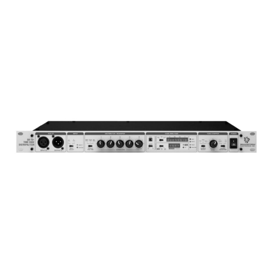
- Page 1 SR-15+ TIME CODE DISTRIPALYZER A Distributor, a Stripper and an Analyzer Operation Manual Software version 3.05 BRAINSTORM ELECTRONICS, INC..Intelligent Solutions For The Recording Studio...
- Page 2 SR-15+ TIME CODE DISTRIPALYZER OPERATION MANUAL BRAINSTORM ELECTRONICS, INC. Release Date: June 1994...
- Page 3 XLR Pins: 1=G / 2=H / 3=L...
-
Page 4: Table Of Contents
Table of contents Page 1 Table of contents • Introduction ....................2 • Section 1: Setting up the SR-15+ Connections ................... 3 Wiring ....................4 Setting the SR-15+’s jumpers ..............6 Setting the SR-15+’s dipswitches ............... 9 • Section 2: Using the SR-15+ 1. -
Page 5: Introduction
Page 2 Introduction Introduction The SR-15+ time code distripalyzer combines three functions in one unit: a distributor, a stripper and an analyzer. It should be permanently installed in your time code set up and always on line, whether you are generating time code and recording it on tape or playing it back while synchronizing several machines. -
Page 6: Section 1: Setting Up The
Set Up Page 3 Section 1: Setting up the SR-15+ 1. Connections ➫ Time Code inputs The SR-15+ has 2 separate input jacks for time code: Input A on the rear panel and Input B (aux) on the front panel. The front panel “Input Select” switch determines which input is active. -
Page 7: Wiring
Page 4 Set Up ➫ Power CAUTION: BEFORE CONNECTING TO AC MAINS BE VERY SURE THAT THE CORRECT VOLTAGE IS SELECTED ON THE REAR PANEL AND THAT THE PROPER FUSE IS INSTALLED. The SR-15+ can operate with 115 VAC / 230 VAC @ 50Hz / 60 Hz. To change selected voltage: disconnect the power cord;... - Page 8 Set Up Page 5 As an input, the jack is connected to the analyzer so that the SR-15+ can report each closure (from an external switch or relay connected to this jack) along with its coinciding time code address. Closure needs to be between tip and sleeve for a minimum of ⁄...
-
Page 9: Setting The Sr-15+'S Jumpers
Page 6 Set Up 3. Setting the SR-15+’s Jumpers There are 5 jumpers on the SR-15+’s mother board that control the 4 different functions listed below. To change the factory settings, remove the chassis’ top panel and move the jumpers as follows: Out - In In - Out Switched - Rear... - Page 10 Set Up Page 7 ➫ Reshaper’s input: “Switched” / “Rear” (JP7) The front panel input selector switch determines which input is active, front or rear. This input signal is reshaped and distributed as well as analyzed by the SR-15+. However, in some situations, it may be convenient to reshape and distribute one signal and analyze another.
- Page 11 Page 8 Set Up ➫ 1/4” Jack: Relay out / Event In (JP4 & JP5) The rear panel 1/4” jack can serve as an input or as an output: • Output setting: the 1/4” jack is connected to an internal relay which is activated whenever the “Good Code”...
-
Page 12: Setting The Sr-15+'S Dipswitches
Set Up Page 9 4. Setting the SR-15+’s Dipswitches (rear panel) There are 8 switches on the SR-15+’s rear COLOR ID VID OUT RELAY TONE OUT VIDEO REFERENCE Isolated (Optional) panel. Most of these switches are reserved for OUT/IN Grounded future upgrades. -
Page 13: Section 2: Using The
Page 10 Analyzer Section 2: Using the SR-15+ 1. Time Code Analyzer The Analyzer section has 3 main functions: • to identify the format and frame rate of the incoming time code; • to verify the proper synchronization (phase) with video; •... -
Page 14: Frame Rate Vs. Format / 29.97 Vs. Drop Frame
Analyzer Page 11 Format vs. Frame Rate The SR-15+’s 4 digit display indicates frame rate, format. There is a distinc- tion. The format does not deal with frequency. It is a way of counting: at 30 fr/sec, the frame sequence is: 28, 29, 00, 01, etc... at 25 fr/sec, the frame sequence is: 23, 24, 00, 01, etc... -
Page 15: Time Code / Video Phase
Page 12 Analyzer B. TIME CODE / VIDEO PHASE What does it mean for time code to be in phase with video? When time code is recorded on video tape, it must be synchronous with the video signal, meaning that the beginning of each time code word must coincide with the beginning of the video frame it describes. -
Page 16: Color Framing
Analyzer Page 13 Color Framing The signals carrying color information within the video signal (chrominance) follow their own cyclic evolution. The relationship between the color sub- carrier and the video sync is too complex to describe here, but it is important to know that this relationship must be maintained during editing to avoid picture disturbance. -
Page 17: Reporting Time Code Errors
Page 14 Analyzer C. REPORTING TIME CODE ERRORS One of the functions of the analyzer section is to detect and report time code errors. Errors considered serious enough to cause a synchronizer problem (such as a repeated frame) are labeled “fatal” by the SR-15+. Others are “non-fatal”. -
Page 18: What Is The Difference Between Reset And Clear
Analyzer Page 15 In addition to the 8 digit display, the SR-15+ also alerts you of errors as follows: ➫ The “Good Code” (input section) blinks off momentarily whenever a “fatal” error is detected. ➫ The Beeper sounds whenever the “ ”... -
Page 19: Transmitting A Time Code Report
Page 16 Analyzer D. TRANSMITTING A TIME CODE REPORT A complete report including “fatal” and “non-fatal” errors as well as format information can be sent to an external printer or computer through the rear panel parallel and serial ports. Using a Printer with the SR-15+ To send a time code report to a printer, connect it to the appropriate port, turn it on and set it so that it is ready to print (“on line”). -
Page 20: Time Code Report
Analyzer Page 17 Time Code Report The time code report includes 7 sections: BRAINSTORM SR-15+ Ver 3.05 Time Code Distripalyzer 1. Header TIME CODE REPORT Alternate Bit Width Window Line 1: BRAINSTORM SR15+ V #.## *** FORMAT *** Line 2: T 30 Drop Frame ISTRIPALYZER Color Bit active... -
Page 21: Serial Time Code Addresses
Page 18 Analyzer Serial Time Code Addresses In some situations, when analyzing time code, it is useful to view each address sequentially to make sure that no frame is missing or repeated etc... Pressing switch #8 on (down position) changes the serial port output so that, instead of transmitting the regular time code report, the SR-15+ uses the serial port to transmit time code addresses to a computer screen. -
Page 22: Tone Stripper
Stripper Page 19 2. Tone Stripper The SR-15+ can extract a pilot tone (at field rate) from time code, video or AC mains. This tone is synchronous with its source. Its zero crossing is synchronous with and its waveform rises at: •... -
Page 23: Distributor / Reshaper
Page 20 Distributor / Reshaper 3. Distributor / Reshaper TIME CODE DISTRIBUTION In today’s studio, more and more pieces of equipment rely on time code for precise timing: console automations, sequencers, DAW’s, readers, synchro- nizers, editors etc... Simply multing a single output of a tape machine or of a generator is not recommended because it can cause serious problems: •... -
Page 24: Selecting The Proper Rise Time
Distributor / Reshaper Page 21 SELECTING THE PROPER RISE TIME Per SMPTE and EBU specifications, the rise time limiting is used to minimize crosstalk from time code into audio. A longer rise time removes more high frequency components from its waveform. However some equipment may not be able to read time code if its rise time is too long. -
Page 25: Section 3: Application Notes
Page 22 Application Notes Section 3: Application notes As a general rule, it is always better to know about time code problems early rather than late in a project. More options are available early on to fix the problem and if it cannot be fixed and you have to start over, at least less time has been wasted. - Page 26 Application Notes Page 23 4. Other applications for the reshaper Dubbing time code Never re-record time code by direct transfer. The accumulated distortions can make it very unreliable. Instead, if no generator is available, patch your time code into the SR-15+ and record the reshaped output. Set the rise time switch to (as needed) and adjust the output level for optimum recording.
- Page 27 Page 24 Application Notes WHAT TO DO ONCE YOU DISCOVERED A PROBLEM? There are many different types of problems that can occur with time code. Many times, the solution will depend of how early in the project it was dis- covered.
-
Page 28: Appendix
Appendix Page 25 Appendix A: Time Code Error Messages: “Fatal” errors are the ones considered serious enough to cause a synchroni- zation problem. All “fatal” errors are reported on the front panel and activate the buzzer and the relay; “fatal” and “non fatal”, both appear on the report, with their corresponding time code address. -
Page 29: B: More On The Frame Rate Counter
Page 26 Appendix Appendix B: More on the Frame Rate Counter... Since the least significant digit’s (LSD) resolution is ± .01 frames per second (.033%), any wow, flutter or speed variation of your time code source is easily detected. a. Time code generators generally display a very steady frame rate with no fluctuation, whether on internal crystal, external video or tone reference. -
Page 30: E: More On The Video Phase Display
Appendix Page 27 Appendix E: More on the video phase display... When the SR-15+ detects F1L5 (actually F1L4 ⁄ as detected by the LM1881 video sync detector), it looks at which bit is in the time code working register. The number of that bit is displayed in the video phase window. -
Page 31: G: Longitudinal Bit Assignment (Smpte & Ebu)
Page 28 Appendix Appendix G: Longitudinal bit assignment: & SMPTE Each word of LTC is divided into 80 equal segments called bits, numbered 0 to 79. These bits are mainly grouped by four into Binary Coded Decimal words to form decimal numbers (0 to 9). Twenty six of these bits are assigned to the Time Address information (frames, seconds, minutes and hours);... -
Page 32: Specifications
Specifications Page 29 Specifications Time Code Reader: 8 digit display - character height: .12” Speed range: reads at play speed only (± 25%) Frame Rate Counter: 4 digit display - character height: .12” Reads: frame rate w/ “Code” selected frequency w/ “Tone in” or “Tone out” selected Reading range: ≈... - Page 33 Page 30 Notes...
- Page 34 BRAINSTORM ELECTRONICS, INC. www.brainstormtime.com Distributed Exclusively by plus24 1155 N. La Brea Avenue, West Hollywood, CA 90038 - USA Tel: (323) 845-1171 - Fax: (323) 845-1170 www.plus24.net...
Need help?
Do you have a question about the SR-15+ and is the answer not in the manual?
Questions and answers