Advertisement
Quick Links
Advertisement

Related Manuals for Brainstorm Electronics SR-15+


Summary of Contents for Brainstorm Electronics SR-15+
- Page 1 ...Intelligent Solutions For The Recording Studio...
- Page 2 SR-15+ TIME CODE DISTRIPALYZER OPERATION MANUAL BRAINSTORM ELECTRONICS, INC. Release Date: June 1994...
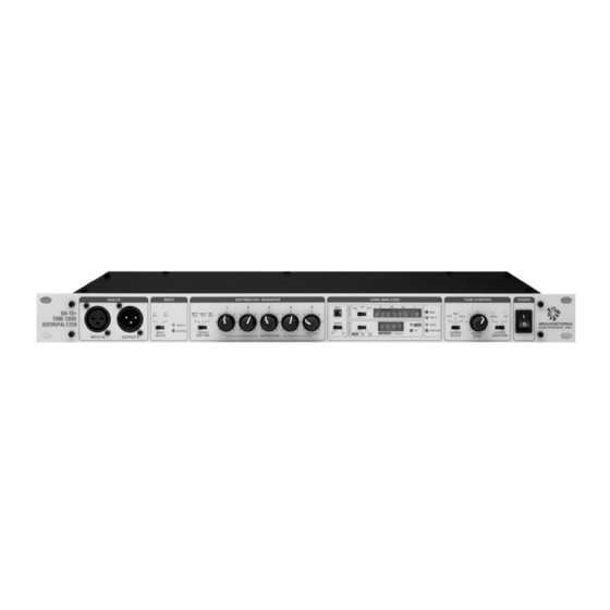
- Page 3 AUX I/O INPUT DISTRIBUTOR / RESHAPER CODE ANALYZER TONE STRIPPER POWER SOURCE INPUT OUTPUT OUTPUT OUTPUT SELECT SELECT RISE TIME WAVEFORM OUTPUT LEVEL LEVEL INPUT B OUTPUT 5 18 19 22 23 Aux I/O Distributor 1. Input B: Auxiliary time code input, for 6.
- Page 5 INPUTS OUTPUTS A (Rear) Time Code B (Front) AC Mains Tone Printer/ Computer Video Video Monitor Color Pulse Good Code Relay out Event In Figure1. SR-15+ Flow Chart...
- Page 6 ➫ ➫ ➫ Ω ➫ ➫ ➫ ➫ ➫...
- Page 7 ➫ Main fuse drawer (hot side) Voltage selector Spare fuse drawer Figure 2. Rear panel power entry module (open) ➫ SR-15+ Input SR-15+ Output Figure 3. Proper unbalanced wiring diagrams ➫...
- Page 8 Relay out Event in Figure 4. 1/4” Jack pins ➫ ➫ 8 pin Mini Din SR-15+ 9 pin Sub-D 8 pin Mini Din Signal Out 2 (TxD) 5 (RxD) Signal In 3 (RxD) 3 (TxD)) Ground 5 (SG) 4 (SG) SR-15+ 9 pin Sub-D 25 pin sub-D...
- Page 9 Figure 5. SR-15+ Top view INPUTS OUTPUTS A (Rear) Time Code B (Front) 3 2 1 AC Mains Tone Printer/ Computer Video Video Monitor Color Pulse Good Code Relay out/ Event in 1 2 3 1 2 3 Figure 6. SR-15+ Flow Chart with Jumpers...
- Page 10 ➫ RESHAPER RESHAPER ANALYZER ANALYZER Figure 8. “Rear” Position Figure 7. “Switched” position RESHAPER ANALYZER Figure 9. With JP7 in “Rear” position, you can analyze the reshaped time code. ➫...
- Page 11 ➫ ➫...
- Page 12 VID OUT COLOR ID VIDEO REFERENCE RELAY TONE OUT (Optional) OUT/IN Parallel Serial Iso Grnd Input Input Loop 1 2 3 4 5 6 7 8 Ground Loop Lift ANALYZER Termination ➫ ➫ ➫ ➫ ➫ ➫ ➫ ➫...
- Page 13 ➫ ➫ ➫...
- Page 14 “Zero” “One” Figure 10. Bit width at 30 fr/sec.
- Page 15 ONE TIME CODE FRAME (12:35:08:28) Sync Word Sync Word F1L5 Video Field 1 F2L5 Video Field 2 F1L5 ONE VIDEO FRAME Figure 11. Proper alignment of time code and video ➫ ➫...
- Page 16 FIELD 1 FIELD 2 FIELD 3 FIELD 4 FIELD 1 FRAME A FRAME B FRAME A Figure 12. NTSC 4 Field Color Sequence ➫ ➫...
- Page 17 ➫...
- Page 18 ➫ ➫ ➫...
- Page 20 BRAINSTORM SR-15+ Ver 3.05 Time Code Distripalyzer TIME CODE REPORT Alternate Bit Width Window *** FORMAT *** 30 Drop Frame Color Bit active User bits: HEX 01234567 *** VIDEO REFERENCE *** Present “V” drive at bit 79 *** START TIME *** 01.00.00.00 24, 25, 30 Drop Frame 30Non Drop...
- Page 22 Sync Word Sync Word F1L5 VIDEO FIELD 1 F2L5 VIDEO FIELD 2 F1L5 Figure 13. Alignment of pilot tone in reference to code and video...
- Page 23 Figure 14. Figure 15. Figure 16. Analog tape machine Analog tape machine Analog tape machine Play speed High speed Low speed...
- Page 24 Figure 17. Figure 18. Figure 19. Reshaped Code Reshaped Code Reshaped Code SMPTE setting (25µs.) Square setting (1µs.) EBU setting (50µs.)
- Page 29 XLR OUT Ω Capacitor Capacitor 100µf 100µf @ 50V @ 50V Cut traces (2 places)
- Page 30 Bit 79 Bit 0 Figure 21. Proper alignment of video and time code ➫ ➫ ➫...
- Page 31 Sync Frame User Frame User Second User Second User Minute User Minute User Hour User Hour User Sync Frame User Frame Word Units Bits Tens Bits Units Bits Tens Bits Units Bits Tens Bits Units Bits Tens Bits Word Units Bits Tens ONE SMPTE FRAME...
- Page 32 ≈ ≈ Ω Ω Ω Ω Ω...
- Page 34 BRAINSTORM ELECTRONICS, INC. www.brainstormtime.com Distributed Exclusively by plus24 1155 N. La Brea Avenue, West Hollywood, CA 90038 - USA Tel: (323) 845-1171 - Fax: (323) 845-1170 www.plus24.net...
Need help?
Do you have a question about the SR-15+ and is the answer not in the manual?
Questions and answers