Table of Contents
Advertisement
Quick Links
Polygraphische innovative
Technik Leipzig
Operation Manual
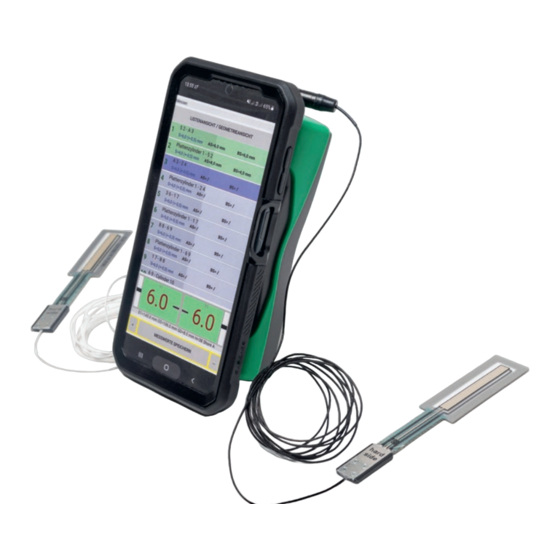
NIP CON SMART
compact
Innovative measuring system for fast adjustment
of the nip width between hard and soft rollers
PITSID Polygraphische innovative Technik Leipzig GmbH
Mommsenstraße 2 | D-04329 Leipzig
EN
Tel +49 341 25942-0 | Fax +49 341 25942-99
EN
info@pitsidleipzig.com | www.pitsidleipzig.com
Advertisement
Table of Contents

Related Manuals for PITSID NIP CON SMART compact


Summary of Contents for PITSID NIP CON SMART compact
- Page 1 NIP CON SMART compact Innovative measuring system for fast adjustment of the nip width between hard and soft rollers PITSID Polygraphische innovative Technik Leipzig GmbH Mommsenstraße 2 | D-04329 Leipzig Tel +49 341 25942-0 | Fax +49 341 25942-99 info@pitsidleipzig.com | www.pitsidleipzig.com...
- Page 2 Index General Information 1.1 Symbols 2 Intended Use and Restrictions on Use 3 Safety Instructions 4 Technical Data 5 Measuring Principle 6 The Measuring System 6.1 Scope of Delivery 6.2 Operation and Control Elements, Connections 6.3 Sensor 7 Operation 7.1 Software Installation 7.1.1 PC 7.1.2 Smartphone 7.2 Connecting the System Components...
-
Page 3: Table Of Contents
Lists These operating instructions support you during the initial start-up, operation and Action Fields maintenance of the contact zone measuring system NIP CON SMART compact. Preview It contains important information, the observance of which ensures safe use. Familia- Measured Value Display rize yourself with this documentation carefully before using the measuring system to avoid personal injury and material damage. - Page 4 The device has degree of protection IP 20. the contact strip width (NIP width). The Contact Zone Measuring System NIP CON SMART compact was developed for deter- Technical Data mining the NIP width in printing presses. It is used for setting and checking the inking and dampening unit hard / soft paired rollers.
- Page 5 Measuring Principle To determine the contact strip width (NIP width), sensors are positioned between the rollers to be measured. By creating pressure in the active sensor area, the width of the contact zone is detected. Sensor jack Wireless link indicator This value depends on the roller diameters, the rubber hardness ON/OFF button and the rubber thickness.
- Page 6 To run the software on the PC, at least the operating system After opening the app, the internal memory under …/My Docu- Windows 7 is required. At least Android 7.0 ("Nougat") must be ments/Documents creates only the folder /NipCon. This folder installed on the smartphone.
- Page 7 Connected hand-held devices cannot establish any further connec- Event Status tions. Hand-held device Newly connected devices are not automatically connected in the PC software. Active connection Establishing connection How to connect the software and hand-held device in the PC version: 1.
- Page 8 The parameter input is completed with the Measure Parameter and measure button. It is not necessary to create a template for simple measurements. □ By activating Save in template, the entered values are perma- √ The parameters for the measuring points can be entered directly. nently assigned to Template Simple measurement.
- Page 9 Positioning the Sensors The sensors must be positioned between stationary rollers. For this purpose, machine functions such as engaging and disengaging the rollers or running the machine in creep speed (inching mode) can be used for this purpose. When positioning the sensors, an accidental reversal of the drive IMPORTANT and operator side must be carefully avoided.
-
Page 10: Measure
7.3.3 Measurement Evaluation and Protocols • Menu • Enter parameters Evaluation • Lists of measurements, measuring points and templates The measurement results are automatically evaluated based on the set-point and tolerance values of the individual roller pairs. • Preview entire measurement task •... -
Page 11: Lists
In the smartphone version, you can choose between a list and a roller diagram (geometry view). Preview of the Entire Measurement Task The preview window provides an overview of the measurement progress. The colour coding of the status information and measured values of individual roller pairs are taken from the list field ( Lists of Templates, Measurements and Measuring Points). - Page 12 File Names With an existing connection between the system components, the The program specifies the names and formats of the templates and measurement charge status of the measuring system is visualized in the background files. The image file of the roller diagram defines the name of the template. of the action field.
- Page 13 7.4.2 Search 7.4.3 Measure Measure menu contains all functions for preparing and performing measure- Search menu item helps you edit and manage your measurement data. It is ments. The functionality in the views is determined by lists (overview), preview, only available on the PC. action field and measured value display.
-
Page 14: Preview
Status information Function Action Color Status information Measure view Templates and measurements (Measure view) Starts measurement based on a template or continues an Start measuring existing measurement Blue Template Copies the file to the protocol list and opens the protocol Print measurement menu Blue !!! -
Page 15: Measured Value Display
Set point comparison Color Result Rubber thickness Rubber hardness Soft roller Software Designation Diameter Yellow Measured value too small (out of tolerance) Set point Green Measured value (within tolerance) Measured value Measured value Measurement Drive side Operator side point Measured value too large (out of tolerance) Tolerance Designation In the event of deviations >... -
Page 16: Protocols
7.4.4 Protocols The measurement data can be printed in the PC-software in the menu item Protocols. Fig. 19. Import / Export view Templates and measurement data must be exported as well as recorded measure- ment data imported for further processing. The separate directories …... -
Page 17: Create Template
7.4.6 Create Template With the left mouse button, a point is set, with the right mouse Simple Measurement template is provided by the software after the program button the last set point is undone. starts. Blue connecting lines between the centers of the circles mark In the Create template menu item, more complex tasks such as roller adjustments... -
Page 18: Settings And Information
▬ Change roller parameters, roller rotation directions, descriptions and sequences of the measuring points The parameter defines the standard serial via Bluetooth connection All rollers and contact points in the preview window are actively ▬ linked to the parameter input. Select the roller or contact point Date / time: information (hand-held device) with the mouse pointer and activate the input field with the left mouse button. -
Page 19: Cleaning
▬ Never use a damaged or defective charger (or USB cable) when charging IMPORTANT Deep discharge can destroy the battery. ▬ Damaged or broken chargers can cause an electric shock! The temperature of the battery during the charging process should not exceed 5…... -
Page 20: Storage, Transportation
PITSID Polygraphische innovative Technik Leipzig GmbH takes over the disposal of Compliance with the following harmonized standards is confi rmed: sent in old devices of the NIP CON SMART compact Measuring System. EN 61326-1:2013: Electrical measuring, control, regulating and laboratory devices... -
Page 21: Warranty
The warranty claim expires if changes to the product by the customer or by third Section 7.1 Software Installation) parties are not agreed upon with PITSID – Polygraphische Innovative Technik Leipzig GmbH and go beyond the activities described in this product. This also applies to... -
Page 22: Error Messages
Error Messages If no measured values can be determined, error messages provide information on operation. Error messages are also visible on the hand-held device via the operating and control elements. ( Chapter 6.2 Operating and Control Elements) Information Cause Action Referral Hand-held Software...
Need help?
Do you have a question about the NIP CON SMART compact and is the answer not in the manual?
Questions and answers