Table of Contents
Advertisement
Quick Links
Product Manual
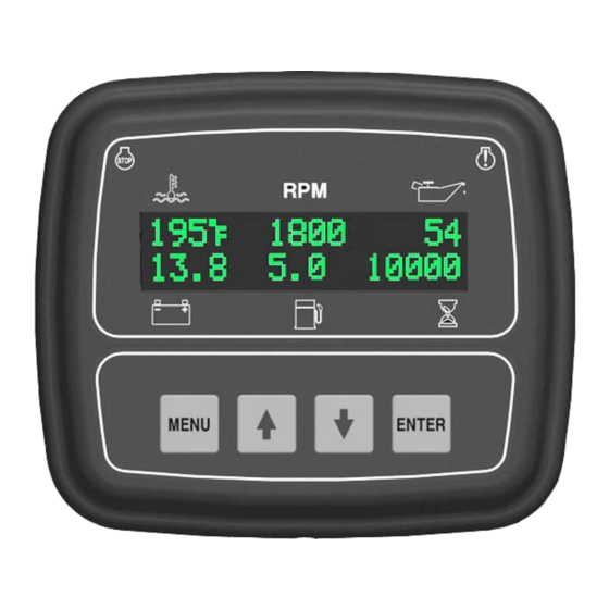
Engine Display & Control
J1939 Engines
Part Number: C3-1610
Revision: 3.0
______________________________________________________________________________________________________________________________________
Copyright Controls, Inc.
P.O. Box 368 • Sharon Center, OH 44274
Phone 330.239.4345 • Fax 330.239.2845 • www.controlsinc.com
Advertisement
Table of Contents

Related Manuals for Controls C3-1610


Summary of Contents for Controls C3-1610
- Page 1 Product Manual Engine Display & Control J1939 Engines Part Number: C3-1610 Revision: 3.0 ______________________________________________________________________________________________________________________________________ Copyright Controls, Inc. P.O. Box 368 • Sharon Center, OH 44274 Phone 330.239.4345 • Fax 330.239.2845 • www.controlsinc.com...
-
Page 2: Table Of Contents
CONTROLS, INCORPORATED C O N T R O L S Y S T E M S & S O L U T I O N S TABLE OF CONTENTS PRIOR TO STARTING ENGINE……... ……………………………………………………………………..……………….…………………………..MANUAL THROTTLE SETTINGS PANEL OPERATION……..……..… ……………………………………….………………………………………….……………………………….. -
Page 3: Prior To Starting Engine
CONTROLS, INCORPORATED C O N T R O L S Y S T E M S & S O L U T I O N S PRIOR TO STARTING ENGINE Prior to starting the engine, select the proper throttle control mode required for application. -
Page 4: Panel Operation
CONTROLS, INCORPORATED C O N T R O L S Y S T E M S & S O L U T I O N S PANEL OPERATION MANUAL OPERATION 1) Engine Start - Turn key to the RUN position... -
Page 5: Module Connector
CONTROLS, INCORPORATED C O N T R O L S Y S T E M S & S O L U T I O N S MODULE CONNECTOR Primary Connector 14 Pin - 4 -... - Page 6 CONTROLS, INCORPORATED C O N T R O L S Y S T E M S & S O L U T I O N S Primary Connector (14 Pin) Function Function Relay #2 – Fuel/Run J1939 Low Relay #1 – Pre Alarm...
- Page 7 CONTROLS, INCORPORATED C O N T R O L S Y S T E M S & S O L U T I O N S PANEL CONNECTORS (RECOMMENDED) 1. Engine Harness Connector –Deutsch 21 pin (HDP24-24-21PE) 21 Pin Engine Harness Connector...
-
Page 8: Engine Alarms, Codes And Messages
CONTROLS, INCORPORATED C O N T R O L S Y S T E M S & S O L U T I O N S ENGINE ALARMS, CODES AND MESSAGES Engine ECU Alarm/De-Rate/Shut Downs It is important to understand panel operation with respect to engine safety protections, alarms, and fault codes. -
Page 9: Pannel Connector
CONTROLS, INCORPORATED C O N T R O L S Y S T E M S & S O L U T I O N S Indicator Lamps The panel red (alarm) and amber (pre alarm) lamp indicators. Engine Engine... -
Page 10: Control Panel Specific Alarms And Shut Downs
CONTROLS, INCORPORATED C O N T R O L S Y S T E M S & S O L U T I O N S CONTROL PANEL SPECIFIC ALARMS AND SHUT DOWNS The panel has its own engine safety alarms and shut downs that can be enabled. These alarms and shut downs are managed by the control panel independent from the engine ECU. -
Page 11: Control Panel Analog And Digital Inputs
CONTROLS, INCORPORATED C O N T R O L S Y S T E M S & S O L U T I O N S CONTROL PANEL ANALOG AND DIGITAL INPUTS The panel is shipped from the factory with the bold print inputs pre-wired and enabled in the panel. - Page 12 CONTROLS, INCORPORATED C O N T R O L S Y S T E M S & S O L U T I O N S Analog 1 Function Options 1) Fuel Level S-W – Fuel amount, in percentage, can be measured and displayed on the C3 module using a standard Stewart Warner scale sender of 240 ohms –...
-
Page 13: Control Panel Relay Outputs
CONTROLS, INCORPORATED C O N T R O L S Y S T E M S & S O L U T I O N S CONTROL PANEL RELAY OUTPUTS The panel is shipped from the factory with the bold print outputs enabled and pre- wired in the panel. - Page 14 CONTROLS, INCORPORATED C O N T R O L S Y S T E M S & S O L U T I O N S f. Pre Alarm & Alarm Horn – Energizes an external audible alarm when a pre alarm or alarm condition is present.
-
Page 15: Menu System
CONTROLS, INCORPORATED C O N T R O L S Y S T E M S & S O L U T I O N S MENU SYSTEM To Enter Menu System Hold the MENU button and press the ENTER button. - Page 16 CONTROLS, INCORPORATED C O N T R O L S Y S T E M S & S O L U T I O N S Main Menus Active Engine Fault Codes View/Scroll Active Fault Codes Stored Engine Fault Codes...
- Page 17 CONTROLS, INCORPORATED C O N T R O L S Y S T E M S & S O L U T I O N S Configuration Menus Input Configuration Analog 1 Input – Set-up Function (Default = None) Digital Input 1 – Pre Set to External Shutdown...
- Page 18 Clear Alarm Log Yes/No (Default = No) CAN Configuration TSC1 Address (Default = 3) Source Address (Default = 44) Engine Address (Default = 1) Oil/Fuel Transmit On/Off (Default = Off) Telemetry Configuration Call Controls, Inc. for more information. - 17 -...
Need help?
Do you have a question about the C3-1610 and is the answer not in the manual?
Questions and answers