Table of Contents
Advertisement
Quick Links
Advertisement
Table of Contents

Related Manuals for Amano AMG-7800 Series


Summary of Contents for Amano AMG-7800 Series
- Page 1 AMG-7800 Series Pay Station Distributor’s Operations Manual...
- Page 2 Amano Cincinnati Inc. reserves the right to make equipment changes and improvements that may not be reflected in this document. Portions of this document may have been updated to include the latest hardware or firmware version, if applicable. We recommend that this document be read in its entirety before any attempt is made to operate the equipment.
-
Page 3: Table Of Contents
Table Of Contents Chapter 1: Introduction .......................1-1 Safety..........................1-2 Chapter 2: Specifications ....................2-1 Cabinet..........................2-1 Electrical .........................2-1 Operational Features ......................2-2 Security ...........................2-3 Coin Section........................2-4 Validator (EOE-108890)..................2-4 Hoppers........................2-4 Bank Note Section ......................2-4 Note Reader - 0 note escrow (EOE-108450) ............2-4 Note Dispenser (EOE-108280) ................ - Page 4 Alarm Log......................4-26 Device Info ........................4-34 Change Device Number..................4-34 Version Check.......................4-35 Help..........................4-35 About Config ......................4-35 Chapter 5: Database Maintenance Utility ................5-1 Database Menu Interface....................5-2 F4 Clock..........................5-3 F6 Language........................5-4 F7 Operator........................5-5 F10 Exit...........................5-8 Chapter 6: Routine Maintenance ..................6-1 Thermal Printer .......................6-1 Status LED's......................
- Page 5 F4 APPL........................7-17 F1 Pay Station...................... 7-17 F2 Maint ....................... 7-17 F3 Rate ........................ 7-17 F4 Reports ......................7-17 F5 Config......................7-18 F6 Explorer......................7-18 F10 Tutorial ......................7-18 F6 Assistant ........................7-19 Enable/Disable Logs Tab ..................7-19 Log Management Tab ..................7-20 Data Import/Export Tab..................
- Page 6 AMG-7800 Distributor’s Operations Manual...
-
Page 7: Chapter 1: Introduction
This manual is intended to be a reference source for the person(s) responsible for installing, configuring and maintaining the AMG-7800 Pay Station. The information contained herein is pertinent to the security of the installation. Only Amano Cincinnati, Inc. authorized service personnel and dealers should have access to this manual. -
Page 8: Safety
Safety • Disconnect the voltage to the equipment during installation and maintenance. • The machine should be hard wired to a feed protected by a 20 AMP circuit breaker. • To avoid fire hazard, only replace fuses with the same type, voltage rating and current rating. -
Page 9: Chapter 2: Specifications
Chapter 2: Specifications Cabinet Figure 2-1: AMG-7800 Dimensions Size: 64-1/4 in (163 cm) H x 31-1/2 in (80 cm) W x 27 1/4 in (69.2 cm) D Weight: 710 - 820 lbs (322 - 372 kg), depending on configuration Housing: Double layer steel. -
Page 10: Operational Features
Operational Features ® Computer: Intel Celeron processor with 512 MB of RAM Communications: • APS (Ethernet/RS-485) between Pay Stations and host PC • Ethernet for Credit Card verification Display: Color liquid crystal VGA (800x600) Coins: • Recognition of 12 different coins (std); 16 special order •... -
Page 11: Security
Security There are eight to nine different keys with different levels of security for accessing sections of the Pay Station. The internal keys (with the exception of the coin box) are identifiable by the last two digits of a six digit alpha-numeric number. KEYS ACCESS IDENTIFIER... -
Page 12: Coin Section
Coin Section Validator (EOE-108890) Acceptable Coin Sizes Diameter: .59 inch (15 mm) to 1.18 inch (30 mm). Thickness: .039 inch (1 mm) to .129 inch (3.3 mm). Hoppers Acceptable Coin Sizes (size dependent on model) Diameter: .75 inch (19 mm) to 1.14 inch (29 mm). Thickness: .05 inch (1.3 mm) to .09 inch (2.3 mm). -
Page 13: Ups (Uninterruptible Power Supply) (Eoe-112880)
3 A max @ 230 VAC Caution!: The PC contains a lithium battery which is not user replaceable. An explosion hazard exists if this battery is replaced with an incorrect type. Refer all servicing to qualified Amano personnel. AMG-7800 Distributor’s Operations Manual / Specifications... -
Page 14: Thermal Printer (C-237200)
Thermal Printer (C-237200) Printing Thermal line dot system Method: Dots per line: Characters per line: Print width: 2.1 - 3.2 inch (54 - 80mm) Resolution: 8 dots/mm Print speed: 7.9 inch (200mm) per second Paper (P/N C-237700) Width: 3.14 inch (80 mm) Thickness: .00256 - .0061 inch (65 - 155 um) Roll Size:... -
Page 15: Chapter 3: Installation
The customer is responsible for making any changes necessary to supply a constant, noise free power line to the AMG-7800. The AMG-7800 Series Pay Station is designed to be installed in an indoor or outdoor sheltered (at least 10 feet from any outside opening) environment, but either location must... -
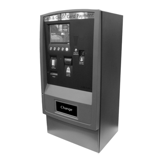
Page 16: Pay Station Configuration
Pay Station Configuration External Figure 3-1: External Configuration Color LCD display Proximity card sensor Buttons for customer as well as Management mode use Ticket and credit card throat Receipt and report dispenser Security lock Speaker for voice instructions and optional intercom Coin acceptor Four way note acceptor Change dispenser (bills and coins) -
Page 17: Internal
Internal Figure 3-2: Internal Configuration Color LCD display PC compartment RWPV mechanism UPS Compartment Thermal Printer Coin box Hopper drawer Bill Dispenser Note Reader Coin Validator AMG-7800 Distributor’s Operations Manual / Installation... -
Page 18: Included Accessories List
Included Accessories List Description Qty. Thermal paper roll Programming card Inventory card Total card G Total card Void ticket box Keys Door outer key Door inner key PC, UPS, Display Access Money Access Banknote Safe removal Banknote Safe open (Optional Banknote Safe removal) Keyboard (stored inside PC compartment) M12 Eye Bolt M12 Plastic plugs... -
Page 19: Prepare The Pay Station
Prepare the Pay Station Unlock the Door The Pay Station Security Lock consists of two parts: An Access Lock: Secures the main locking mechanism. This lock is essentially a plug which must be removed in order to reach the inner lock. The Inner Lock: Secures the Pay Station door. -
Page 20: Remove The Bill Dispenser
Remove the Bill Dispenser 1. Unlock and open the Pay Station Door. 2. Unlock (two #66 keys) and swing open the Bill Dispenser Door. Figure 3-4: Unlock the Bill Dispenser Door 3. Pull the dispenser out from the Pay Station until it stops. Figure 3-5: Remove the Bill Dispenser AMG-7800 Distributor’s Operations Manual / Installation... -
Page 21: Remove The Mounting Nuts And Clamps
4. Disconnect the Power Cable and Communications Cable. Caution!: The following step should be performed by two people to avoid possible personal injury or damage to the equipment. 5. Disengage the rails by lifting up on the left Rail Release Lever and pushing down on the right Rail Release Lever and carefully slide the unit out of the Pay Station. - Page 22 The following figure shows correct placement of the Pay Station: Figure 3-7: Mounting the Pay Station The wiring conduits must be placed at the indicated position. The conduits should extend no higher than 2" (5.2 cm). 1. Using the template, install four 3/8" mounting studs (not supplied) at the positions marked by the four outer holes.
-
Page 23: External Wire Connections
External Wire Connections The AC and Communication/Control wiring is located in the right rear corner of the Pay Station. The Coin Box and Bill Dispenser need to be removed to facilitate easy access to these areas. The AC Junction Box is mounted along the bottom right side of the cabinet under the power supplies. -
Page 24: Connect Ac Power
Connect AC Power The AC Junction Box is mounted along the bottom of the right side of the cabinet. Remove the junction box cover by removing the two Cover Screws. Use the wire nuts provided inside the box to secure the AC connections. For safety, the following precautions must be observed: Installed AC power cabling must be routed through a separate conduit from the DC and communication wiring. -
Page 25: Communications Panel
Communications Panel The TC Converter (RS-485 interface for the APS-NET) along with the Ethernet coupler are mounted on the Communications Panel. The panel is located in the right rear corner of the cabinet above the AC panel. Figure 3-10: Communications Panel 3-11 AMG-7800 Distributor’s Operations Manual / Installation... - Page 26 APS-NET Wire Connections The APS-NET wiring is for RS-485 communications when the Pay Station is part of a network controlled by a host PC. We recommend the use of twisted pair shielded cable (Belden 9842 or equivalent) for this connection. 1.
-
Page 27: Intercom Connections
Intercom Connections Standard Intercom The standard intercom installed in the Pay Station is designed to be interfaced to an Aiphone™ LEF series intercom system. The Intercom wiring is connected to a terminal block (TB1) on the rear of the I/O PCB located on the upper right panel of the Pay Station cabinet. - Page 28 A jumper wire must be installed between pins 1 & 3 of TB1. The signal (Aiphone designation 1) is connected to pin 2. The common (Aiphone designation -) is connected to pin 1. The following figure illustrates the Intercom Terminal Block connections corresponding to Aiphone documentation.
- Page 29 Optional Intercom The optional intercom interfaces with a GAI-TRONICS Dial-Up intercom system. The Intercom PCB is mounted to the right of the I/O PCB (right panel of the Pay Station cabinet). It is provided with a cable attached to TB2. The other side of this cable has a female RJ11 connector to connect a standard phone line cable.
-
Page 30: Replace The Coin Box
Replace the Coin Box You must reset the security mechanism inside the Coin Box before it can be reinstalled in the Pay Station. 1. Unlock the cover (turn cover key 90° clockwise). 2. Lift the cover off and remove it. Figure 3-15: Reset the Coin box 3. -
Page 31: Replace The Bill Dispenser
Replace the Bill Dispenser Warning!: Pay Station power must be off before reconnecting the Bill Dispenser. Damage to the Bill Dispenser and Pay Station power supply could occur from a power surge if the power is on. 1. Press the Guide Rails into the fully retracted position in the Pay Station. 2. - Page 32 3-18 AMG-7800 Distributor’s Operations Manual / Installation...
-
Page 33: Chapter 4: Configuration
Chapter 4: Configuration All system configuration parameters for the country in which the Pay Station is being installed are set up at the factory. Under ordinary circumstances it will not be necessary to modify the default configuration. The PC keyboard included with the Pay Station and connected to the Pay Station computer must be used in order to view or modify the configuration. -
Page 34: File
File The File drop down menu provides options for exiting the program and launching the Pay Station, Rate Setup, Maintenance or Reports. Exit simply closes Configuration which can also be accomplished by clicking on the "X" in the upper right corner of the window. Setup Selecting Setup will display the following drop down menu. - Page 35 YES. “Out Of Service” will be indicated on the display and the machine will not process tickets. The default is YES. Keep Alive Timeout: This defines the time (in seconds) in an Amano Single Wire facility, that the Pay Station will wait for a polling response from the facility host before recording an entry in the APS log.
- Page 36 Note Disp Installed: Confirms the presence of the Note Dispenser. The default is YES. Note Disp Low Threshold: Sets the quantity of notes in a cassette below which the Pay Station will consider the stock low. The default is 200. Note Val Installed: Confirms the presence of the Bank Note Reader.
- Page 37 3 - Round Math (default): 1 through 2 cents will be rounded to 0 cents, 3, 4, 6 and 7 cents will be rounded to 5 cents and 8 through 9 cents will be rounded to 10 cents. Single Wire Host: (YES or NO). If the facility is using Amano’s Single Wire system, this parameter must be set to YES.
-
Page 38: General
General The "General Scheduler" provides a means to set a time for the Pay Station computer to perform an automatic maintenance re-boot. Maintenance: The re-boot is set to at a specific time every day (0 – 23 hours; 0 = midnight). -
Page 39: Format
Format The "Format" options define the formats of the currency, date and time which will be printed on receipts. The "Get Windows Settings" button in each window will set the values to the current Windows system settings. Currency: Currency Name: Default is US dollar. Symbol: "$"... - Page 40 Time: Sample: Displays the time in the currently selected format. Style: Enter the format for displaying the time. (The default is HH:mm). Separator: Enter the symbol to serve as the separator in the time display. 12-Hour Clock: Select this box if you want the time displayed in 12-hour format. (The default is 24-hour format).
- Page 41 Date: Short Date: Sample: Displays the short date in the currently selected style. Style: Pull down menu for selecting the Short Date style. The default is “MM/dd/yyyy”. Long Date : Sample: Displays the long date in the currently selected style. Style: Pull down menu for selecting the Long Date style.
-
Page 42: Receipt
Receipt This selection defines the formatting of the printed receipt. Clicking on Receipt will display the following window. Each tab at the top of the window selects a different portion of the receipt to edit. To modify or define an area of the receipt, select the respective tab. The Header, Footer and Ticket tabs are universally applied to all receipts except for “Lost”... - Page 43 The specific heading for a data field (which can be anything you like) that you wish to print on the receipt is entered (typed) on the left side of the editing box before the semicolon. The variable to be used for the field is selected by highlighting the desired variable from the "Insert variable"...
- Page 44 Insert Variable Menu Default Heading Variable Name Variable Description Amount of Change [CHANGEAMT] The change tendered by the Pay Station. Amount Paid [PAIDAMT] The amount of money tendered to the Pay Station. Amount Short of change [SHORTAMT] The amount of change owed to the customer if the Pay Station runs out of cash for making change.
- Page 45 Ticket Transactions Each area of the receipt which is defined under a tab appears in a specific order that cannot be changed; these areas will be explained in order of their appearance. Normal Ticket Transaction A Normal Ticket represents the majority of transactions. The areas of a ticket and the corresponding tab used to define each area are indicated in Figures 4-1 to 4-3.
- Page 46 Figure 4-1: Normal Transaction Receipt Format - Cash 4-14 AMG-7800 Distributor’s Operations Manual / Configuration...
- Page 47 Figure 4-2: Normal Transaction Receipt Format - Short 4-15 AMG-7800 Distributor’s Operations Manual / Configuration...
- Page 48 Figure 4-3: Normal Transaction Receipt Format - Credit Card 4-16 AMG-7800 Distributor’s Operations Manual / Configuration...
- Page 49 Lost Ticket Transaction A Lost Ticket transaction is assigned a specific rate to be charged to patrons who have lost their Entry Ticket. The format of the receipt issued is defined by the Lost tab. 1. Lost: The parameters for a Lost Ticket replaces the Header in a Lost Ticket receipt. All the other areas of the receipt are listed in the same order as Normal Tickets.
-
Page 50: Translate
The programmed translations for the English words and phrases are viewed through this window. Note: If you need to modify any of the translations, contact Amano Technical Support for assistance. The Next and Back buttons will sequentially step through all the phrases in the Date Format and Pay module databases. - Page 51 Print Setup Pressing Print Setup will display a window allowing you to print selected translations on the receipt printer. Module(s): You can select to print translations from All Modules or just the Date Format or Pay Modules from the drop down menu. Text ID: Enter the range of Text ID’s you want to print Languages: Select which language translations to print from the drop down menu: •...
-
Page 52: Coin Reader Setup
Note: These parameters are set at the factory to tell the Pay Station how the Coin Validator has been configured and should not be changed. If there is a need to recognize a different coin than those programmed, contact your Amano representative. Channel Info: Denominations: The dollar value of the coins programmed in each validator channel. - Page 53 Hopper Info: There can be up to four hoppers installed in the Pay Station. They are designated 1 through 4, starting from the back of the machine. Hopper 4 is always a non-recirculating (stocked manually and used only to make change) hopper. Capacity of the Coin Box: All overflow from the hoppers as well as denominations recognized but not assigned to a recirculating hopper will be routed to the Coin Box.
-
Page 54: Banknote Reader
Banknote Reader The denominations of bills the Banknote Reader will accept are defined here. Model: CashCode. Capacity of the Notebox: The Notebox safe capacity is set to 800 bills. Denominations: The seven denominations programmed are $1., $2., $5., $10., $20. and $50. Accept: A check in the box adjacent to each denomination instructs the Pay Station to accept the selected bill. -
Page 55: Note Dispenser
Note Dispenser This window sets the configuration of the Bank Note Dispenser. Dispenser Info: The Note Dispenser can be up to a three Cassette dispenser. The cassettes in the dispenser are numbered from the top down, with the top slot correlating to Cassette 1. Capacity of the Dispense Box: Each cassette can hold up to 2000 bills. -
Page 56: Transactions
Transactions The “Transactions” option will display the following window through which all the transactions in the current database can be viewed. The “Top” and “Bottom” button go the beginning and end of the transaction list, respectively. The “Back” and “Next” buttons step backwards and forwards through the list sequentially. - Page 57 Rate and Amount: The Rate & Amount tab displays the rate information used to calculate the fee and the monetary details of the transaction displayed. Machine Number: The number of the Pay Station. Transaction: The sequential number of the transaction being displayed. Rate Type: The rate is either “A”...
-
Page 58: Alarm Log
Alarm Log The Alarm Log option will display the following window from which all Pay Station alarms stored in the database can be examined. The “Top” and “Bottom” button go to the beginning and end of the transaction list, respectively. The “Back” and “Next” buttons step backwards and forwards through the list sequentially. - Page 59 4-27 AMG-7800 Distributor’s Operations Manual / Configuration...
- Page 60 4-28 AMG-7800 Distributor’s Operations Manual / Configuration...
- Page 61 4-29 AMG-7800 Distributor’s Operations Manual / Configuration...
- Page 62 4-30 AMG-7800 Distributor’s Operations Manual / Configuration...
- Page 63 4-31 AMG-7800 Distributor’s Operations Manual / Configuration...
- Page 64 4-32 AMG-7800 Distributor’s Operations Manual / Configuration...
- Page 65 4-33 AMG-7800 Distributor’s Operations Manual / Configuration...
-
Page 66: Device Info
Device Info The Device Info menu has one option: Change Device Number The default Device Number is number 1. This does not need to be changed unless the Pay Station is being networked with other machines. This number will appear in the "Device Num"... -
Page 67: Version Check
Version Check Selecting Version Check will display this window with a pull down menu which lists the current version of the following Pay Station components including major and minor revisions and the date of the latest revision: Pay Station: This selection will display the current version of the Pay Station software. RTP: This selection shows the current version of the Real Time Processing driver. - Page 68 4-36 AMG-7800 Distributor’s Operations Manual / Configuration...
-
Page 69: Chapter 5: Database Maintenance Utility
Chapter 5: Database Maintenance Utility You must use the standard PC keyboard included with the Pay Station in order to use the Maintenance Utility. The keyboard is stored in the PC compartment (unlocked with a #64 key) along with a work shelf that can be temporarily mounted to the two screws in front of the RWPV mechanism shelf. -
Page 70: Database Menu Interface
Database Menu Interface The following interface will be displayed: Instruction Window displays instructions and error messages. Data Entry Window displays the window title and the database fields requiring the entry of parameters. These parameters are manually entered from the ranges displayed in the Summary Window. -
Page 71: F4 Clock
F4 Clock The F4 Clock key allows the setting of the system time and date. 1. System Clock Date: Press the F1 Chg Date key and enter the date in the System Clock Date field. The machine will automatically insert the slash “/” delimiters. Press F9 Save. The Instruction Window will prompt you to re-enter the date for confirmation. -
Page 72: F6 Language
F6 Language The Language key defines the language options that will be displayed on the Pay Station during normal operating mode. 1. Default Language: Select the default operating language desired from those displayed in the Summary Window. All transaction screens will be displayed in the selected default language unless a configured alternative language is selected from the opening screen. -
Page 73: F7 Operator
F7 Operator The F7 Operator key allows you to specify the access privileges for holders of Universal Management Cards. This card is a configurable card that is created using the AGP-9700 Encoder. The parameters set here will define the operator as having either Management Card or Programming Card privileges, each with access to the specific functions of each card type desired for the operator. - Page 74 Operator (Page 2 of 4) These address fields are optional: you can enter as much or as little information as your requirements dictate. 1. SSN #: Enter the Social Security Number of this user. 2. Address: Enter the street address of this user. 3.
- Page 75 Operator (Page 4 of 4): Programming Select either Yes or No from the Summary Window for each listed utility: Yes will enable this card to access a utility and No will exclude the utility. Operator (Page 4 of 4): Inventory Select either Yes or No from the Summary Window for each listed function: Yes will enable this card to perform a function and No will exclude the function.
-
Page 76: F10 Exit
F10 Exit Pressing F10 Exit from any menu will display this screen: Pressing any of the selections will run the listed program. The F1 Pay Station key will restart the Pay Station in the Normal Operating mode. Pressing ESC or F12 will return to the Maintenance screen. AMG-7800 Distributor’s Operations Manual / Database Maintenance Utility... -
Page 77: Chapter 6: Routine Maintenance
Chapter 6: Routine Maintenance Thermal Printer The Thermal Printer is mounted to the inside of the Pay Station door. Figure 6-1: Thermal Printer Status LED's These four LED's, numbered from right to left, indicate the printer status. The following table describes the meaning of these indicators regarding routine servicing of the printer. LED 4 LED 3 LED 2... -
Page 78: Installing Paper
Installing Paper Install thermal paper into the printer as follows: 1. Make sure all old paper has been removed from the mechanism (see Removing Paper). 2. Install the new paper roll onto the Paper Spool with the paper unrolling in a counter- clockwise direction, as indicated on the Paper Thread Label. -
Page 79: Removing Paper
Removing Paper Remove paper from the printer as follows: 1. Press down on the Platen Release Lever to raise the Platen and gently pull the paper out of the mechanism. 2. Squeeze the end of the Paper Spool together to release the Retaining Ring and paper roll and slide the both off of the spool. -
Page 80: Read, Write, Print, Vault (Rwpv) Unit
Read, Write, Print, Vault (RWPV) Unit The primary function of the RWPV mechanism is to read, encode and print on magnetic stripe tickets. It also reads the magnetic stripe on credit cards submitted for payment. The mechanism contains an area to hold one ticket when a second (ticket or card) is inserted and another area to vault (store) tickets that are not retrieved from the throat of the mechanism. -
Page 81: Ribbon Replacement
7. When finished, tilt the printer assembly back into place and securely snap the release latches into place. Warning!: Use only an RWPV ribbon (Amano part number CE-316250). This ribbon contains an ink tank which will assure long ribbon life ... -
Page 82: Coin Section
Coin Section The coin section option of the AMG-7800 consists of four major components: 1. Validator: Checks that a coin is valid currency and then routes the coin to one of the Hoppers or the Coin Box. 2. Passive Manifold: Accepts a coin from the Validator and guides it to the appropriate Hopper. -
Page 83: Coin Validator
Coin Validator The Coin Validator is programmed to accept the coins of the country where the Pay Station is being installed. Up to sixteen different coin and/or token combinations can be programmed to be detected and routed to one of three different Hoppers or the Coin Box. In case a Hopper gets completely filled, the Validator is programmed to route any additional coins to the Coin Box until the Hopper becomes partially depleted by making change. -
Page 84: Hoppers
Hoppers The Pay Station can be ordered with up to four hoppers. The hoppers are configured at the factory for the denominations required by the customer. Maintenance Unlock the Hopper Drawer (key #66) and pull it open via the Pull Hole to access the hoppers. - Page 85 2. Select Hoppers. 3. Select Fill 4. Select the hopper you need to fill. AMG-7800 Distributor’s Operations Manual / Routine Maintenance...
- Page 86 5. Add to Coins to the selected hopper. 6. After filling the hopper with coins, enter the number (quantity, not value) of coins deposited by pressing the appropriate keys: +100, +10, +1. If you make a mistake, pressing Reset will zero the count and you can start over. The coins entered will be reflected in the display.
- Page 87 Empty Coins If it is necessary to empty a coin hopper, proceed as follows: 1. Enter Management Mode. Select Inventory and then Hoppers as described under Adding Coins. 2. Select Empty. This option allows you to zero the contents of selected Hoppers. The following screen will appear: 3.
- Page 88 The printer will automatically print the Empty Hoppers Report. The top section is the Coin Hoppers Report which lists the total contents of all hoppers after emptying. The Ejected Coins section displays the coins that were actually emptied. Figure 6-11: Empty Hoppers Report 6-12 AMG-7800 Distributor’s Operations Manual / Routine Maintenance...
- Page 89 Coin Box Maintenance of the coin box consists of simply removing the box and emptying the coins contained within. Prior to emptying the coin box, the user should enter the management mode with a valid Management Card. Upon removal of the coin box, the inventory of the box will be printed in a Coin Box Total Report and the count maintained in memory will be automatically zeroed and rolled over into the GT SUB (see Chapter 2 of the AMG-7800 Supervisor’s Operations Manual (ANP-2001xx)) database.
- Page 90 • Coinbox seq #: This is a sequential number indicating the number of times the Coin Box has been emptied since the last GT(Grand Total) report was generated (see Chapter 2 of the AMG-7800 Supervisor’s Operations Manual (ANP-20010x)). The number increments by one each time the Coin Box is removed. The count is zeroed when a GT report is run.
- Page 91 Remove the Box 1. Insert the key into the Coin Box retaining lock and turn it 180° clockwise. Note: The assembly is spring loaded; press the box towards the back of the cabinet to remove pressure while turning the key. Figure 6-13: Remove the Coin Box 2.
- Page 92 Empty the Coin Box 3. Unlock the cover (turn cover key 90° clockwise). 4. Lift the cover off and remove it. 5. Empty the Coin Box. Figure 6-14: Empty and Reset the Coin box 6. Using a ballpoint pen or similar rigid object, rotate the Reset Lever in the cover slightly clockwise and down.
-
Page 93: Bank Note Section
Bank Note Section The Pay Station Bank Note section is divided into two segments: 1. The Bank Note Reader, which can be either a standard reader or an optional note reader. Each reader consists of: a. Bank Note Reader: Verifies the validity of the currency and passes the bills to the bank note safe. -
Page 94: Bank Note Reader Maintenance
Bank Note Reader Maintenance Emptying the Bank Note Safe Prior to emptying the Bank Note Safe, the user should enter the management mode with a valid Management Card. Upon removal of the safe, the inventory of the contents will be printed in a Note Box Total Report and the count maintained in memory will be automatically zeroed and rolled over into the GT SUB (see chapter 2 of the AMG-7800 Supervisor’s Operations Manual (ANP-2001xx)) database. - Page 95 • Notebox seq #: This is a sequential number indicating the number of times the Note Safe has been emptied since the last GT(Grand Total) report was generated (see Chapter 2 of the AMG-7800 Supervisor’s Operations Manual (ANP-2001xx))). The number increments by one each time the Coin Box is removed. The count is zeroed when a GT report is run.
- Page 96 Empty the Bank Note Safe Bills accepted by the Bank Note Reader are deposited in the Bank Note Safe. There are two different keys required to access the safe. 1. Key #66: This key unlocks the retaining latch so that the safe can be removed from the reader.
- Page 97 Figure 6-18: Opening the Note Safe 5. Open the cover and remove the bills from the safe. 6. Close the cover, secure the lock and latch and remove the key. 7. Return the safe to the reader. 8. Turn key #66 counterclockwise to secure the safe in place. 6-21 AMG-7800 Distributor’s Operations Manual / Routine Maintenance...
- Page 98 Clearing Jams: Bank Note Reader If a Bank Note Reader jam occurs, either due to a malfunction, deteriorated bank notes or attempted fraud, the reader will be taken off line. This is indicated by the bill icon not appearing on the display when an entry ticket is submitted to the Pay Station. The LED's on the front of the reader will be blinking red.
-
Page 99: Bank Note Dispenser Maintenance
Bank Note Dispenser Maintenance The Note Dispenser can have up to three cassettes, each of which can hold up to 2000 bills of a given denomination. Each cassette must be inserted into the slot in the dispenser for which its denomination is programmed. Slot assignments are always programmed in increasing value, from the top slot down. - Page 100 Replenishing Bank Notes Note: Prior to adding bills to a cassette, that cassette must be emptied (see page 6-28) and Bank Note Dispenser Alarms cleared (see page 6-29). The empty procedure is the only way to unlatch cassettes so they can be removed from the Bill Dispenser for filling.
- Page 101 6. Pull the cassette being filled out of the dispenser chassis. 7. Insert the key into the lock on the left side of the cassette and turn 1/4 turn clockwise to unlock. Open the cassette by pressing the release button and lift the lid. Figure 6-21: Open Bill Cassette 8.
- Page 102 RELIABLE CASSETTE LOADING 6-26 AMG-7800 Distributor’s Operations Manual / Routine Maintenance...
- Page 103 9. Return the cassette to the dispenser chassis. 10. Enter the quantity of bills being deposited by pressing the appropriate keys: +100, +10, +1. If you make a mistake, pressing Reset will zero the count and you can start over. The bills entered will be reflected in the display.
- Page 104 Emptying Bank Notes Note: Prior to adding bills to a cassette (see page 6-24), you must zero the contents using the following procedure in order to unlatch the cassette from the Bank Note Dispenser. To remove currency from the dispenser, unlock the Bill Dispenser Door and proceed as follows: 1.
- Page 105 5. Press Exit to return to the Inventory menu. The printer will automatically print the Empty Bins Report. The top Dispenser Bins Report section lists the total contents of all bins after the emptying activity. The bottom Removed Notes Report section displays the bins that were actually emptied.
- Page 106 Emptying the Reject Vault If the dispenser senses an error when issuing change, it will feed the questioned bills into the reject vault and then re-issue the change. The vault should be checked whenever stocking the dispenser. The bills, if usable, can be restocked to the dispenser bins.
- Page 107 Figure 6-27: Emptying the Reject Vault 4. Place the vault on a flat surface. Unlock and remove the padlock securing the Reset Lever. 5. Rotate the Reset Lever counterclockwise until it stops. Lift up on the cover to open while holding the lever in the position. 6.
- Page 108 Figure 6-28: Clear Note Feeder Jam (view from back of dispenser) 3. Close the lid and press gently until the retainers latch (you must hear both latches click into place). 4. Repeat the process for the other Note Feeder Lids. Note Qualifier Jam The Note Qualifier is above the top Note Cassette compartment.
- Page 109 Note Transport Jam You need to remove the Top Cover of the dispenser to clear a jam in the Note Transport mechanism. 1. Slide the Bill Dispenser out of the Pay Station until it stops. 2. Remove the cables from the Cable Retainers and position away from the dispenser to allow clearance to lift the cover.
-
Page 110: Ups
The Uninterruptible Power Supply protects the Pay Station from poor quality AC line power. Protection is provided from surges, low voltage, high voltage and complete power failure. Under normal circumstances, UPS operation is fully automatic and requires no user intervention. If the power fails, the UPS will initiate an emergency shutdown of the Pay Station. -
Page 111: Front Panel Indicators And Switches
Front Panel Indicators and Switches The following figure indicates the location and function of the front panel switches and indicators. Figure 6-33: UPS Front Panel Off Button Press and hold the Off button until the panel indicators turn off and the unit powers down to turn power to the outlets off. - Page 112 Line Voltage LED This indicator is green and will light steadily when power is being supplied from the AC line and voltage is normal. Cut AVR (Auto Voltage Regulator) LED This LED lights yellow when the UPS is reducing high line voltage. Battery Charge This bank of five LEDs displays the percentage of battery capacity remaining in twenty percent increments.
-
Page 113: Maintenance
Maintenance Preventative Maintenance The best preventive maintenance measure is to keep the area around the UPS clean and relatively dust free. Clean the outside of the system periodically with a vacuum cleaner. Battery Life The unit has an operating temperature range of between 32° and 104° F (0° and 40° C). Full battery life can be achieved by keeping the unit at the ideal ambient temperature of 77°... - Page 114 1. Power down the Pay Station by turning of the main Power Switch. Make sure the UPS has completely shut down prior to proceeding. 2. Remove the two screws securing the Front Cover and remove the cover. Figure 6-34: Remove the Front Cover 3.
- Page 115 4. Use the Pull Tab to slide the Battery Pack partially out the Battery Compartment, so that the cables are accessible. Figure 6-36: Remove the Battery Pack 5. Note the orientation of the two batteries. Disconnect the black cable from the (-) terminal of the bottom battery and the red cable from the (+) terminal of the top battery.
-
Page 116: Remove The Pc
An explosion hazard exists if this battery is replaced with an incorrect type. Refer all servicing to qualified Amano personnel. All the cable connections are at the front of the PC and are detailed on the following page. - Page 117 Figure 6-39:PC Connections 6-41 AMG-7800 Distributor’s Operations Manual / Routine Maintenance...
- Page 118 6-42 AMG-7800 Distributor’s Operations Manual / Routine Maintenance...
-
Page 119: Chapter 7: System Diagnostic Utility
Chapter 7: System Diagnostic Utility The PC keyboard must be connected to the Pay Station computer in order to use Diagnostics. A Keyboard Stand is provided to facilitate easy interface with the computer. The stand has two keyhole slots that can be mounted to the bolts on the front of the RWPV mechanism shelf. -
Page 120: User Interface
User Interface The following interface will be displayed: Instruction Window displays instructions and error messages. Data Entry Window displays the window title and the database fields requiring the entry of parameters. These parameters are manually entered from the ranges displayed in the Summary Window. Summary Window displays a list of the minimum and maximum values for the selected field in the Data Entry Window. -
Page 121: F1 Tests
F1 TESTS Pressing F1 Tests from the Diagnostics menu will launch the Diagnostic utility. This program runs diagnostics of all the major components and peripheral equipment of the Pay Station. Prior to proceeding with diagnostic tests, you must set the Bank Note Acceptor type and the Currency (US or Canadian) type under the Options tab. - Page 122 BNA Options Select the Bank Note Acceptor installed in the Pay Station from the drop down menu. Coin Section Options Select either US or Canadian coins from the drop down menu. Eject Coins Test This will allow you to test the hopper coin ejection mechanism. Press Eject Coins to begin the test.
-
Page 123: Diagnostics Tab
Diagnostics Tab The devices that can be tested are listed at the top of the window. Selecting a device will place a check mark in the adjacent box. If multiple devices are selected, they will be tested in sequence when the Diagnose button is pressed. The Information window will list the results of each test. - Page 124 Bank Note Acceptor Test This test will initialize the Bank Note Acceptor and place it in note acceptance mode. When the Information Window displays the “ready for bill” line, insert a bill (any denomination) into the Bank Note Acceptor. Note: You must specify the Bank Note Acceptor type under the Options Tab prior to proceeding with this test.
- Page 125 Bank Note Dispenser Test This test will query the Bank Note Dispenser for its status, reset the dispenser and display the results. I/O Diagnostics This option will test the buttons and indicator lights on the front panel and all the internal sensors in an automated sequence.
- Page 126 The display will prompt you to check the indicator lights on the front panel. Press Button 1 on the front panel to indicate YES if the specified light is ON and Button 2 for NO if it is not. After testing the lights, the Pay Station alarm will be activated briefly from the same test screen.
- Page 127 Door Open: A check should appear here as soon as the test begins, as the door is already open. Door Key: this is the sensor in the Door Access lock. As this is already removed to open the door, a check should appear here automatically. Hopper Drawer: Unlock and open the Hopper Drawer.
- Page 128 Coin Section Test This test verifies the functioning of the Coin Validator. Place a check in the box adjacent to each coin denomination you want to check and press Start. Follow the prompts and insert the specified coin denomination(s) as requested. The Pay Station will accept the coin, route it to the correct hopper and eject the same denomination from the hopper.
- Page 129 Printer Test This will test the Receipt Printer by printing all available characters and then cutting and ejecting the results. 7-11 AMG-7800 Distributor’s Operations Manual / System Diagnostic Utility...
-
Page 130: F2 Aps
F2 APS Pressing F2 APS from the Diagnostics Menu will display the following menu. APS allows a technician monitor communications within the Facility Management System for diagnostic purposes. F1 Start/Stop Pressing F1 Start/Stop will run APS and will alternately start and stop monitoring APS communications with the Facility Management Software. - Page 131 F1 Start Log F1 Start Log will start the log recording, disable F1 Start Log and enable F6 End Log. The log is maintained in the following file on the PC hard drive: “C:\parking\logs\commlog.txt” F2 Pause Pressing F2 Pause will pause the display of the log and enable navigation keys. Use the navigation keys to scroll through the log listing recorded up to the time that F2 Pause was pressed.
-
Page 132: F3 Data
These functions can erase the entire database. If a database problem exists, run F3 Repair and re-check the integrity of the database. If the problem persists, contact Amano Technical Support to archive the data before you run F1 Clear to clear the database. -
Page 133: F2 Initial
After selecting the tables to be cleared, press the F9 Clear key. The Instruction Window will display a warning that the database will be cleared and the Status Indicator will flash yellow as a warning. Press F9 Clear again to clear the selected tables. The Instruction Window will then indicate “All tables have been cleared”. -
Page 134: F3 Repair
F3 Repair Pressing F3 Repair from the Data Menu will attempt to repair corrupt database tables. If there is a problem with a database, this option is worth trying before clearing the database tables. Press F3 Repair and the Instruction Window will indicate “Repairing Tables”. Warning!: Do not turn off the Pay Station or try to access any other functions ... -
Page 135: F4 Appl
F4 APPL Pressing F4 Appl from the Diagnostics Menu displays a menu for launching other Pay Station utilities and starting the Pay Station operating system. F1 Pay Station This key starts the Pay Station operating system. F2 Maint This key starts the Pay Station Maintenance utility, which provides a means for setting the system clock, setting language options and assigning access rights to operations. -
Page 136: F5 Config
F5 Config Pressing F5 Config from the Applications Menu will start the system Configuration program. See Chapter 4 of this manual for more details. F6 Explorer Pressing F6 Explorer from the Applications Menu will launch the Microsoft Windows Explorer®. F10 Tutorial This function is not implemented. -
Page 137: F6 Assistant
Caution!: Enabling logs will noticeably inhibit the transaction speed of the Pay Station. Amano only recommends the use of this feature for diagnostic purposes. When diagnostics are complete, de-activate logging to ensure full Pay Station performance. -
Page 138: Log Management Tab
Software Logs This section enables logging of the software components of the Pay Station. • Pay Station Operations: Interaction between all Pay Station components (hardware and software). • User Interface: Actions of all user interface components (buttons, switches, etc.). • Debit Recharge Function: Every action of a Debit Recharge transaction. - Page 139 Log Window This window displays the logs that are currently stored on the Pay Station hard drive. A log with a check in its box will be exported to a file when the Export button is pressed. A greyed out check box means that the log contains files that cannot be deleted (see “Files For Window”).
-
Page 140: Data Import/Export Tab
Export: This button will export the files of all selected files to a .zip file in the root directory (F:\) of a USB flash drive connected to a USB port in the Pay Station PC, from where it can be examined by Amano technicians. If there is no USB drive installed, the following prompt will display: Either insert a flash drive and press OK or press Cancel, which will display a window from where an alternate (internal) drive can be chosen. - Page 141 Import Window This window displays information on the source and status of the import file. This function will restore previously exported system data and configuration, replacing the current files in the Pay Station. You must enter the Equipment Number of the Pay Station you are importing to prior to proceeding.
-
Page 142: F7 Lpt Setup
Thermal Printer. The configuration should only be modified if a new printer is being installed or under specific instructions from Amano Technical Support. When launching LPT Setup, the following prompt will appear: Press Cancel to abort the launch or Connect to proceed. -
Page 143: Dip Switch
Dip Switch Upon pressing Connect, the utility will read the printer configuration and display the following window: The displayed settings are correct for the Pay Station and can be used to configure the printer if your settings deviate. The following functions are available on this screen: •... -
Page 144: Status
Status Pressing the Status button will display the following window: While displayed, the Status window will continuously monitor the listed parameters in real time. If a listed condition applies, a check will appear in the adjacent box. • Unconnected to the Printer: There is no communication with the printer. •... -
Page 145: Chapter 8: Reports
Chapter 8: Reports Reports is a utility for generating reprints of Total and Inventory Reports (see AMG-7800 Supervisor’s Operations Manual (ANP-2001xx)), Discount Reports consisting of discount assignment and usage, system activity Journal Reports, Credit Card transaction reports, and Debit Recharge account Replenishment reports. The PC keyboard included with the Pay Station must be connected to the Pay Station in order to use the Reports Utility. -
Page 146: User Interface
User Interface The screen displayed below is the interface to the Reports utility. Take a moment to familiarize yourself with the items shown. Instruction Window displays instructions and error messages. Data Entry Window displays the window title, the page number, number of pages in the set and the database fields requiring the entry of parameters. -
Page 147: Credit Card Reports
Credit Card Reports Highlighting this selection in the Summary Window and pressing F8 Next Pg displays the following Reports screen. The Credit Card Report contains a list of all Credit Card transactions that have been processed with the clearing house on a specified Process Date. -
Page 148: Credit Card Type
Credit Card Type This field defines the type of Credit Card to include in the report. A list of available Credit Card Types appears in the Summary Window. Select All, an individual credit card type, or Other (if you wish to include Diner’s Club and Carte Blanche credit cards.) Process Date The last ten Credit Card Process Dates with their associated range of Transaction Numbers appear in the Summary Window. - Page 149 Figure 8-1: Credit Card Summary and Detail Reports AMG-7800 Distributor’s Operations Manual / Reports...
-
Page 150: Inventory Reprint
Inventory Reprint Selecting this option and pressing F8 Print will reprint all Total Reports, Inventory Status Reports and inventory maintenance activities (filling or emptying Coin Tubes, Coin Hoppers, and Bill Dispenser) generated the last time a Management Card was inserted in the RWPV. -
Page 151: Do Transactions
Do Transactions: Select Yes to include all transactions for the time period indicated in this report. Select No to omit transactions. Do Events: Select Yes to include all events for the time period indicated in this report. Select No to omit events. -
Page 152: From
From: This is the date and time from which the report is to begin. Select the month, day, year and time from the selections in the Summary Window. This is the date and time the report is to end. Select the month, day, year and time from the selections in the Summary Window. - Page 153 Figure 8-2: Discount Summary and Detail Reports AMG-7800 Distributor’s Operations Manual / Reports...
-
Page 154: Replenishment Report
Replenishment Report Highlighting this report and pressing F8 Next Page displays the following reports screen. The Replenishment Report details the total number of Debit Recharge Replenishment transactions and the value of the funds applied to each recharge account for the selected time period. -
Page 155: Send To
Send To Tell the system where the report is to be sent. The selections in the Summary Window are A: ( external USB floppy disk drive ), C:(the root directory of the system hard drive) or Printer (the Pay Station’s thermal printer). Figure 8-3: Replenishment Summary report 8-11 AMG-7800 Distributor’s Operations Manual / Reports... - Page 156 Figure 8-4: Replenishment Detail Report 8-12 AMG-7800 Distributor’s Operations Manual / Reports...
-
Page 157: Chapter 9: Troubleshooting And Repair
Chapter 9: Troubleshooting And Repair This chapter covers troubleshooting and repair procedures for field serviceable sections of the Pay Station as well as replacement procedures for modules that must be returned to the factory for service. RWPV Unit For any service other than clearing a jam or replacing the print ribbon the RWPV unit will have to be removed from the Pay station. - Page 158 4. Loosen (do not remove) the mounting screws holding the DTF in place. Slide the DTF to the rear of the Pay Station until it clears the RWPV and lift up and over the RWPV to remove. Figure 9-2: Remove the optional DTF Mechanism 5.
- Page 160 ANP-200001 • Copyright © 2010 • Printed in U.S.A . • Software Version 3.2 • 09/10/0...
Need help?
Do you have a question about the AMG-7800 Series and is the answer not in the manual?
Questions and answers