
Related Manuals for Baxi Slim HP


Summary of Contents for Baxi Slim HP
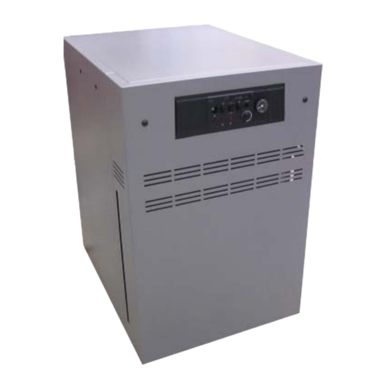
- Page 1 Slim HP Slim HP Slim HP Die cast high yield boiler Ionisation and electronic ignition check Fume safety thermostat 83 / 99 / 116 kW Réf. : BAXI - 1373 - I - EN - 0 - 09 / 04...
- Page 2 Contents General General specifications Installing the boiler Installing the boiler Maintenance Refitting the heating unit (in case disassembly on site) CC 170 control module...
- Page 3 The boilers are fitted to operate with natural gas group G 20 - 20 mbar. For any gas change see chapter 4.4. BAXI certify compliance of all boilers mentioned in this manual in reference to the appliances of the corresponding types, having the rights of use of the EC Marking according to the European Directives for "Gas appliances"...
- Page 4 General characteristics Characteristics of the gas CE Nr 1312BS5053 Category 2Esi 3P Type cof fume duct B11BS 52.9 108 126 Design heat flow rate Low rate heat rate 31.7 64.8 75.6 Design useful power 48.7 66.2 82.8 99.4 115.9 Low rate useful power 29.2 39.7 49.7 59.6 69.5 Number of elements Number of burners...
- Page 5 Main dimensions 1190 Outlet Ø F Inlet of Backflow Bleed tap Ø 1/2 Number elements 1080 1100 1160 1000 Sizes in mm 1003 1013 Ø F (outside) Ø blackflow Rp 1" 1/4 Rp 1" 1/2 Ø outlet - inlet of gas R 1"...
- Page 6 3.2 Hydraulic connection Installing the boiler Fitting the boiler Connection to the heating circuit is performed at the back of the heater. Connecting the facility to the water mains must be The boilers are designed to be installed without a base, on performed according to currently enforced rules of the art and the floor of the boiler room, provided it is flat, sturdy, dry regulations, and using a CB disconnector to fill the heating...
- Page 7 Hydraulic connection diagrams Setting valve IMPORTANT: The hydraulic connection diagram of each Decantation drip dynamic installation must be determined together with the corresponding regulation. 3-channel valve Primary pump SHW load pump Boiler SHW exchanger Outelet Backflow Condenser Gas connection The gas connection is ensured on the rear left of the heater. Connection to chimney Boiler Boiler...
- Page 8 Installation diagram recommended Connect the phase to the strip’s L terminal. The line must withstand an intensity of 6.3A under 230V 50 fume duct Ø Hz + Ground (check that power of the pump(s) is compatible). Implement the electric connection as shown in the electrical diagram of the instruction set.
- Page 9 Commissionning the boiler Connecting 2 valves Ignition transformer - Connection with components Gas pressure switch Main valve (6-channel connector) dual rating (9-channel connector) Electricaly connect the control module and the various components : Thermostat and - Ignition transformer and gas pressure switch (connector, thermometer bulbs 6 channels), - dual ratings main valve (9-channel connectors)
- Page 10 Before commissionning, check the compliance of the burner equipment with the supply gas. The gas ramp - burner set is factory set dor design pressure and reduced pressure (see gas characteristic page 4). If a modification of the injector pressure is required, proceed as follows: - loosen the pressure screws at the injectors located on the gas ramp and check the pressure with a pressure...
- Page 11 Commissionning the boiler The boilers are supplied factory set for using natural gas type G 20, with the kit matching the customer’s request. Refer to the user instruction set of the boiler For applications with Propane 50 or 150 mbar (see gas Adaptation to another gas characteristics in page 4), il you have to replace or else change the following elements:...
- Page 12 Maintenance The sweeping and maintenance operations must be performed by a skilled professional. BAXI waivers any liability for damage resulting from work performed by non qualified staff and lack of compliance with these instructions. The guarantee conditions require the operation, preventive and corrective maintenance of the boiler performed satisfactorily.
- Page 13 Untighten the M5 screws on the control bracket without removing them, lift and pull towards you. If required, disconnect the connectors, the supply cable, and remove the bulbs from the sensor pocket (refer to § 4 page Remove the gas inlet bracket Untighten the M 5 screws on the left and right panels, at the back and front of the boiler...
- Page 14 Removing the burner disconnect the power supply. Close the gas protection tap Remove the top, front panel and 2 removable panels (refer to § 5.1 A-B-C-D 230 V - 50 Hz page 12) Disconnect the control module from the valves unscrew the gas valve union nut (beware the flat gasket) remove the bottom sheet...
- Page 15 Sweeping We recommend performing at least once per year a sweeping of the heating body. Remove the top panel (refer to § 5.1 A-B page 12) Remove the draft hood flap Engage the sweeping brush between the fins vertically, in the axis of the gas chimneys Refit the draft hood flap and check the sealing...
- Page 16 Operating incidents Boiler does not start - check the power supply is available and that the orange indicator is lit, - check that the thermostats and regulations are in demand, - check that the overheating thermostat is not activated, - press the rearming button, restart the boiler and perform the complementary checks: •...
- Page 17 - using the same method, secure the left end element (Fig. 5). REASSEMBLY OF THE HEATER - lay the end element on the ground on the outlet side (left (in case of on-site dismantling to reach the boiler in the example) at its final location, and check the room to follow the following instructions) centering of the 1 branching in the «A»...
- Page 18 FITTING THE GASKETS Elements Size B Pull the cast iron body backflow collector by 15 to 20 mm using a lever (chisel - screwdriver). Insert the gaskets at an angle, by placing the base in the slot and the top against the collector (Fig.
- Page 19 Place the sealing insulating strips onto the boiler block (one horizontal, one vertical, and one folded with a square) Place the 2 insulating pads on the right and left end elements Fit the draft hood on the sealing strips to ensure it is between the embossings for fitting elements Fit the draft hood using the...
- Page 20 CC 170 control Description Safety thermostat test push button Thermometer showing General switch the boiler’s temperature On - OFF Fuse CC 170 6,3 AT Burner lock out reset push button 6.3 AT Over heating safety thermostat Over heating lamp Power ON lamp Pressure gauge Burner lock out lamp Schématic diagram CC 170...
- Page 21 CC 170 wiring diagram Heating pump 230Vac N L1 50 Hz G D V U Y X 61 21 TR1 TR2 21 4 CC 170 42 61 63 80 66 11 6 4 5 7 8 9 10 12 3 1 2 11 6 4 5 7 8 9 10 12 3 1 2...
- Page 22 7.2 Operation 7.4 Electrical Connection The thermostat is a two-stage model. The setpoint The wiring system should comply with current regulations. temperature can beadjusted within a range from 30 to 90ºC. - Provision should be made for the installation to include a Once the setpoint temperature has been set, the burner’s switch, a circuit-breaker or other omnipolar disconnect 2nd stage stops 10K before reaching it, also causing the...
- Page 23 NOTES: ..............................................................................................................................................................................................................................................................................................................................................................................................................................................................................................................................................................................................................................................................................................................................................................................................................................................................................................................................................................................................................................................................................................................................................................................................................................................................................................................................................................................................................................................................................................................................................................................................
- Page 24 93158 Le Blanc-Mesnil - Cedex Téléphone : + 33 (0)1 45 91 56 00 Télécopie : + 33 (0)1 45 91 59 50 BAXI S.A. au capital de 43 214 640 € RCS Bobigny B 602 041 675 A.P.E 282 D...
Need help?
Do you have a question about the Slim HP and is the answer not in the manual?
Questions and answers