Table of Contents
Advertisement
Quick Links
Advertisement
Table of Contents

Subscribe to Our Youtube Channel
Related Manuals for Packet Power BGS16


Summary of Contents for Packet Power BGS16
- Page 1 BGS16 Multi-Circuit Monitoring System Installation, Operations and Maintenance Manual Version 2.0 Packet Power 2716 Summer St NE Minneapolis, MN 55413 1-877-560-8770 www.packetpower.com © 2021 Packet Power, LLC Packet Power Multi-Circuit Monitor BGS16 User Manual V2.0...
-
Page 2: Section 1: General
BGS16 should only be connected to the type of power source indicated on the label. The current transformer(s) used with the BGS16 must be appropriate to the amperage of the circuit(s) on which they will be used. - Page 3 Packet Power Multi-Circuit Monitor BGS16 User Manual V2.0 Packet Power LLC assumes no liability for user’s failure to comply with these safety guidelines. Please read this entire manual carefully before proceeding. This symbol is used throughout this manual to indicate critical safety information.
-
Page 4: Regulatory Information
Packet Power Multi-Circuit Monitor BGS16 User Manual V2.0 Regulatory Information Monitoring Units This product has been tested to the following requirements: CONFORMS TO UL/IEC STD 61010-01, 3rd ed.IEC 61010-2-030 ed. 1.0, EN 61010-1:2010, CSA C22.2 NO. 61010-1 IEC 61010-2-032 - Edition 2 - Issue Date 2002/09/01, EN 61010-1:2001, IEC 61010-1, 3rd Edition ... -
Page 5: Using This Manual
Monitoring System (“BGS16”) and associated devices. It is a supplement to information provided in the support section of Packet Power’s web site www.packetpower.com/support. The BGS16 must be used in conjunction with a Packet Power Ethernet Gateway. Detailed information about the Ethernet Gateway can be found on the web site above, including information needed to access data from the BGS16 for use in a third-party monitoring application. -
Page 6: Table Of Contents
Packet Power Multi-Circuit Monitor BGS16 User Manual V2.0 Index SECTION 1: GENERAL ...................... 2 HAZARDS ..........................2 Regulatory Information ......................4 Using this Manual ......................... 5 Index ............................. 6 SECTION 2: OVERVIEW ....................7 Supported Voltage Service Types ..................7 Current Transformers ...................... -
Page 7: Section 2: Overview
Ensure that the type of voltage service that is present in the equipment you are monitoring matches the type indicated on the label of the BGS16. The BGS16 cannot be used on 480V equipment if access to N is not present nor on 600/347V circuits. The BGS16 is powered from the voltage source it is monitoring. -
Page 8: Communication
Each Gateway can support up to fifty BGS16s; additional Gateways can be added for capacity or redundancy. The BGS16 must be able to establish a wireless connection either directly to a Gateway or to another Packet Power wireless device. -
Page 9: Components
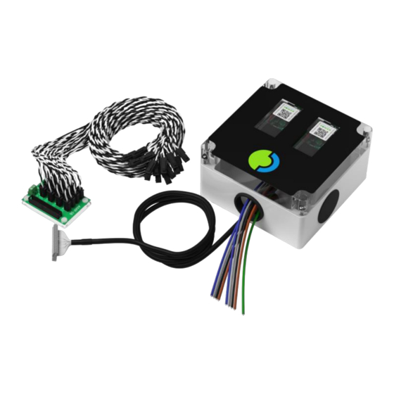
Packet Power Multi-Circuit Monitor BGS16 User Manual V2.0 Components The BGS16 consists of a NEMA 1 monitoring enclosure, one CT interconnect board with loose CT leads or wire harnesses for attaching CTs, and the CTs themselves. © 2021 Packet Power, LLC... -
Page 10: Section 3: Installation
3. Do not make adjustments to the BGS16’s internal wiring. 4. If you believe the BGS16, CTs, interconnect boards or leads have been damaged, do not attempt to repair or use them. All components are built to spec by Packet Power and are not intended for alteration in the field. - Page 11 Enclosure dimensions Wire exits The BGS16 has openings for wire exits in the back, bottom and on each side of the enclosure allowing it to be mounted in a variety of positions relative to the equipment being monitored. Wire exit location Description 1”...
-
Page 12: Voltage Connection
BGS16. If a three-pole breaker is not used, you must ensure suitable over-current protection is provided. The BGS16 comes pre-wired. It is configured to work with one of the supported voltage types. Unless otherwise specified, the unit has inline fuses on each voltage phase. The wire count and color mix will vary based on the voltage service type (see diagrams on the following pages). - Page 13 Packet Power Multi-Circuit Monitor BGS16 User Manual V2.0 Voltage wire connections by service type © 2021 Packet Power, LLC Page 13 of 27...
- Page 14 Packet Power Multi-Circuit Monitor BGS16 User Manual V2.0 © 2021 Packet Power, LLC Page 14 of 27...
-
Page 15: Ct Interconnect Cable And Board
Packet Power Multi-Circuit Monitor BGS16 User Manual V2.0 CT Interconnect Cable and Board The CT Interconnect Board is connected to the BGS16 via the CT Interconnect Cable. The interconnect cables and boards are labeled if multiple BGS16s are shipped to one location. -
Page 16: Cts
(or wire harness) will be attached to the CT Interconnect Board. Each CT lead will have a label (standard labels are CT1, CT2, CT3, etc.). The BGS16 supports 6 to 16 split core or Rogowski coil CTs of varied amperage and size. SPLIT CORE CTs... - Page 17 Packet Power Multi-Circuit Monitor BGS16 User Manual V2.0 Connect CTs to conductors 1. Disconnect power to the BGS16 if possible. If it is not possible to disconnect power, always treat CT leads as though they carry line voltages. Work on live panels must only be performed by qualified personnel.
- Page 18 Packet Power Multi-Circuit Monitor BGS16 User Manual V2.0 Connect Rogowski coils to conductors 1. Disconnect power to the BGS16 if possible. If it is not possible to disconnect power, always treat the coil leads as though they carry line voltages. Work on live panels must only be performed by qualified personnel.
-
Page 19: Section 4: Operations
Each BGS16 has a unique 16-digit ID number that can be found on a label located on the outside of the unit in the top left corner. Each component meter also has a unique 16-digit ID number on the meter’s front label. -
Page 20: Shutdown
Shutdown No special preparation is required prior to shutdown. Using a customer-provided disconnect such as a 3-pole breaker, simply shut off power to the BGS16. Note that this disables power to the monitoring unit only. The conductors on which the CTs are installed will still have live load and must be treated accordingly, and the panel itself will still have live voltage and present a risk of electrocution. - Page 21 If a number of readings are missing, ensure the CT Interconnect Cable is securely connected to the associated CT Interconnect Board. If the BGS16 powers on but no meters are able to establish communications with a Gateway, contact Packet Power support.
-
Page 22: Section 5: Maintenance
Packet Power Multi-Circuit Monitor BGS16 User Manual V2.0 SECTION 5: MAINTENANCE Equipment Parts List Contact Packet Power support if you encounter issues related to any parts or before attempting any repairs. Of these items, the following can be replaced in the field by qualified personnel: ... -
Page 23: Scheduled Maintenance
Customers are encouraged to keep firmware current by applying updates once a year or whenever a critical firmware release is issued. Firmware updates can be arranged via Packet Power support and are available for all devices under warranty. This includes the original manufacturer’s warranty or the optional extended service warranty purchased after the manufacturer’s warranty ends. - Page 24 Packet Power Multi-Circuit Monitor BGS16 User Manual V2.0 ROGOWSKI COIL SENSOR 1. Disconnect power to the BGS16 if possible. If it is not possible to disconnect power, always treat the coil leads as though they carry line voltages. Work on live panels must only be performed by qualified personnel.
-
Page 25: Dismantling
Packet Power Multi-Circuit Monitor BGS16 User Manual V2.0 Dismantling The BGS16 contains components that may fall under local electronics disposal guidelines. Please adhere to local requirements. No lead is used in the BGS16. Emergency Measures Contact Packet Power support at 1-877-560-8770 or support@packetpower.com. -
Page 26: Appendix: Sample Panel Detail
Packet Power Multi-Circuit Monitor BGS16 User Manual V2.0 APPENDIX: SAMPLE PANEL DETAIL Packet Power’s “Monitoring Made to Measure” approach allows for each BGS16 unit to be customized to your needs. The panel detail provides important information on how your BGS16 was produced. - Page 27 Packet Power Multi-Circuit Monitor BGS16 User Manual V2.0 © 2021 Packet Power, LLC Page 27 of 27...
Need help?
Do you have a question about the BGS16 and is the answer not in the manual?
Questions and answers