Table of Contents
Advertisement
Advertisement
Table of Contents

Related Manuals for Skov DOL 339


Summary of Contents for Skov DOL 339
- Page 1 DOL 339 Climate and Production Computer Technical Manual...
- Page 3 According to EU directives 98/58/EU an alarm system must be installed in any house that is mechanically ventilated. Please note that the product liability clause of SKOV A/S' general terms and conditions of sale and delivery specifies that an alarm system must be installed.
-
Page 4: Table Of Contents
7.2.1 Menu for Show Connection ....................22 7.2.2 Manual I/O Allocation ......................23 7.2.3 Connecting a UPS (Uninterruptable Power Supply) to DOL 339 ........23 7.2.4 Settings for Winch Motor ...................... 24 7.2.5 Setting of CAN Addresses ..................... 25 7.2.6 Setting of CAN Termination Jumpers (max. - Page 5 Setting of Stand Alone Heaters ....................55 7.8.2.6 Setting of Spray Cooling ......................55 7.8.2.7 Setting of Pad Cooling ......................55 7.8.2.8 Setting of Pressure Sensor ..................... 55 7.8.2.9 Adjusting the CO Sensor ...................... 55 DOL 339 Climate and Production Computer...
- Page 6 7.11.1.2 Setting of Minimum Air Inlet ....................75 7.11.1.3 Adjusting the Active Pressure ....................75 7.12 Adjustment of Stepless Unit ....................76 Troubleshooting Guide ................77 Table for Temperature Sensor Control ................77 TECHNICAL DATA DOL 339 Climate and Production Computer...
-
Page 7: Procedure
Technical Manual PRODUCT DESCRIPTION This technical manual deals with the installation of the DOL 339 climate and production computer and is primarily aimed at electricians who are to mount, install and test the computer. A certified electrician must carry out the installation in accordance with applicable national rules and in Europe in accordance with applicable EU rules. -
Page 8: Mounting Guide
Technical Manual MOUNTING GUIDE Figure 1: Outline of connections DOL 339 Combi-Tunnel Figure 2: Outline of connections DOL 339 Tunnel DOL 339 Climate and Production Computer... - Page 9 Technical Manual Figure 3: Outline of connections DOL 339 LPV Figure 4: Outline of connections DOL 339 production DOL 339 Climate and Production Computer...
-
Page 10: Mounting Of Dol 339 Together With Dol 278
Technical Manual 1 Mounting of DOL 339 together with DOL 278 DOL 339 DOL 278 Figure 5: Mounting of DOL 339 together with DOL 278 and wiring box DOL 339 Climate and Production Computer... -
Page 11: Mounting Of Dol 339
10 cm (3.9”) (C) below the cabinet base for air cooling. • 10 cm (3.9”) (D) on the right side for operation of the AUT/MAN (Auto/Manual) change- over switches. (16,9”) (3,9”) (3,9”) Figure 6: Mounting of DOL 339 climate computer DOL 339 Climate and Production Computer... -
Page 12: Mounting Of Auxiliary Contactor
Figure 7: Mounting of auxiliary contactor Do not place contactors in the climate computer as this causes electrical disturbance which will make the computer reset/restart. 4 Mounting of DOL 278 Emergency Opening See Technical Manual regarding the emergency opening. DOL 339 Climate and Production Computer... -
Page 13: Mounting Of Climate Sensors
• On the shady side of the house to avoid the sun. Take into account that the altitude of the sun varies with the seasons. • As much in the open as possible, but protected from rain and snow. DOL 339 Climate and Production Computer... -
Page 14: Installation Guide
6 Electric Connection Connecting Cables Connect cables according to the three basic wiring diagrams which correspond to the emergency opening of the system. See the document DOL 339 Cable Charts and Wiring Diagrams. 6.2 Setting of Mains Voltage IMPORTANT Before you connect the mains voltage, it is important to set the voltage in the computer so that it corresponds to the voltage level in the local house. -
Page 15: Technical Menus
CPU module Main I/O General I/O Weighing modules Operation log Service Manual/auto Setting CF-card Control parameters Adjust negative pressure Adjust stepless 1 Advanced control parameters Default system Diagnostics Table 1: Outline of technical menus DOL 339 Climate and Production Computer... -
Page 16: Selecting Components
CF card. Press to return to the main survey. Press when is selected to gain access to the installation menu. Select components in the DOL 339 installation menu ( Technical Setup Installation No more components than practically possible can be selected. -
Page 17: Menu For Installation
1 zone Zone mode: 2 zones Sensors Temperature sensors Humidity sensor Pressure sensor CO2 sensor CO2 sensor Auxiliary sensors Pressure sensor NH3 sensor O2 sensor Temperature sensor Humidity sensor Air speed sensor Wind dir. sensor DOL 339 Climate and Production Computer... - Page 18 Pad sensor 1-2 Yes/No Pad slave relay 1-2 Humidification No/ 1 Relay Humidification Soaking No/ 1 Relay Soaking Inlet de-ice Cycle time Stop flaps Only open Info Matic Table 2: Outline of installation menu DOL 339 Climate and Production Computer...
-
Page 19: One- And Two-Zone Control
Adjustment Climate Zone controlled inlets The installed temperature sensors are associated with an air inlet zone. If there are several sensors in a zone, DOL 339 calculates an average temperature according to which it will control. The menu Climate Ventilation... -
Page 20: Active Functions When The Control Fails
: When the control fails, spray cooling is not active. Note that in an emergency situation DOL 339 cannot regulate according to temperature and humidity. If you select ), spray cooling runs no matter whether the Active at failure temperature is too low and humidity is too high in the house. -
Page 21: Icing Air Inlet
Control Parameters fans in the outlet units for a short period of time, e.g. two minutes. This will also contribute to prevent ice formation in the air inlets. DOL 339 Climate and Production Computer... -
Page 22: Connecting Components
When a component requiring allocation of an I/O is installed, the following happens: 1) DOL 339 allocates all I/Os according to a prioritized list. This means that if priority 1 I/O is free, DOL 339 will select it. -
Page 23: Manual I/O Allocation
The terminal is not in use Select the required terminal, and press Enter If you use a terminal that is currently used by another function (indicated by *), DOL 339 will automatically change the I/O allocation for this function. Check in the menu... -
Page 24: Settings For Winch Motor
• Set the S5 slide switch on the override switch module to ON There are no settings on the HI-power relay module and it cannot control 24 V winch motors either. Figure 9: Settings for winch motor DOL 339 Climate and Production Computer... -
Page 25: Setting Of Can Addresses
*The address switch X10 on the weighing module is not to be changed, as it is only used when there are more then 10 weighing modules. I/O module Weighing Weighing module 1 module 2 Figure 10: Setting of CAN-Addresses DOL 339 Climate and Production Computer... -
Page 26: Setting Of Can Termination Jumpers (Max. 1 Meter)
ON/OFF CAN TERM 2) Set the jumper ” ” to ON. ON/OFF Terminate OFF(1) 2 input weigher module ON (2) ON OFF Terminate Max. 1 metre Figure 11: Setting of CAN-Termination Jumbers (max. 1 meter) DOL 339 Climate and Production Computer... -
Page 27: Setting Of Can Termination Jumpers (Max. 200 Meters)
ON/OFF EXT-TERM CAN ON (1) OFF (3) INT-TERM. 2 input weigher module ON (4) ON OFF EXT-TERM. ON (2) 230V-240V ON OFF Max. 200 metres Terminate Figure 12: Setting of CAN-Termination Jumbers (max. 200 meters) DOL 339 Climate and Production Computer... -
Page 28: Extra Supply To Hi-Power Relay Modules/Switch Modules
This is necessary because the flat cable cannot bear the 24 V power consumption to 30 or 40 HI-power relays alone. Do not install more than two HI-power relay modules or four LO-power relay modules without installing an extra wire. Figure 13: Extra Supply to HI-power Relay Modules/Switch Modules DOL 339 Climate and Production Computer... -
Page 29: Adjustment
Technical Manual 7.3 Adjustment This section describes the adjustment of the system. This adjustment is typically made only once to determine how the DOL 339 climate and production computer controls the climate. 7.3.1 Menu for Adjustment Adjustment Climate Temp. sensors setup Temp. -
Page 30: Setting Of Temperature Sensor
Brooding in Full house 7.3.1.3 Drum Scale The value for , quantity of fill depends on whether DOL 339 is set up for pan feeding or Drum scale destination feeding. Pan feeding: Weight per weighing. Destination feeding: The maximum weight per weighing. -
Page 31: Calibration
Pad sensor 1 Calibration offset 1 Drum scale Calibration weight Start calibration Start calibration Calibration state Calib. with weights Calibrate empty Calibration finished Calibration value Calibration date Calibration deviation Table 4: Outline of the Calibration menu DOL 339 Climate and Production Computer... -
Page 32: Calibrating The Air Inlet And Air Outlet
After installation, adapt DOL 339 to the winch motor. During this automatic calibration, the flaps open and shut completely for a short time and will then move to the position which DOL 339 calculates. Setting of the time, it takes for the flap to open and close. -
Page 33: Calibrating The Electronic Silo Weighing Module
(The more weight in the silo, the more precise the calibration will be. Min. 100kg) During calibration, DOL 339 will generate an alarm for Missing I/O. This is normal and due to the fact that the communication between the computer and the weighing module is disconnected. - Page 34 9) Load the silo with a known test load (the available weight at the time of the calibration). 10) Wait a few seconds until the weigher has settled at a certain weight. 11) Return switch #2 to “NORMAL” position. DOL 339 Climate and Production Computer...
- Page 35 2000kg, the calibration plumb must weigh min. 8kg and max. 800kg. • if errors occur when data are saved. The error can be remedied by: • Setting switch 1, 2, 3 and 4 to NORMAL. • Pressing the RESET button. • Repeating the calibration. DOL 339 Climate and Production Computer...
-
Page 36: Calibration Of Drum Scale
Calibration weight Setting the required max. calibration weight. 20.00 kg Start calibration Calibration activation. The DOL 339 returns to OFF by itself when the calibration is finished. Calibration state Read-out of the course of calibration. Wait for scale Calibrate with weights... -
Page 37: User Setup
Contrast Table 5: Outline of the User setup menu 7.5.1.1 Setting of Measuring Units DOL 339 can display metric and US units. 7.5.1.2 Setting of Screen The brightness and contrast of the screen can be set for optimum reading in relation to the current placement of the computer. -
Page 38: Service Information
Tabel 6: Outline of the Service information menu 7.6.1.1 Operation log The operation log saves the latest 35 changes to settings and the time of the changes. When all 35 storage locations are used, the oldest change will disappear. DOL 339 Climate and Production Computer... -
Page 39: Testing
2) that the alarm system works as intended. Press enter to end the test. The test should then be carried out every week. 7.7.1.4 Testing the DOL 278 Emergency Opening Unit See the Technical Manual for the emergency opening unit. DOL 339 Climate and Production Computer... -
Page 40: Testing Optional Components: Manual Control
Humidification Humidification relay 1 ON/OFF Soaking Soaking relay Measured value Pressure sensor Actual value Measured value CO2 sensor Actual value Aux. sensor 1- 4 Auxiliary sensors ON/OFF Emergency inlet Emergency inlet Ventilation Vent. requirement DOL 339 Climate and Production Computer... - Page 41 Bird 1 calibration value Light relay Light dimmer 24-hour clock 1-4 24-hour clock Info Matic test Received telegrams Receive percentage Table 7: Outline of the Manual/Auto menu (changeable values are highlighted in bold type). DOL 339 Climate and Production Computer...
-
Page 42: Testing Climate Functions
Technical Manual In the menu, DOL 339 displays the components selected under the Manual/Auto Installation menu. You should test the components one at a time. Automatic control: The computer should normally be in automatic control mode. Manual control: During start, or in a service situation, it may be convenient to control the individual functions manually. - Page 43 In internal fan speed controller mode, the emergency change-over switch AUT/MAN (automatic/manual) on the side of DOL 339 must be set to AUT (see figure 9). Set the computer to...
- Page 44 7.7.3.1.6 Testing Sequential Heating Set the computer to and select the menu Auto Technical/ Service/ Setting/ Climate/ Heating/ House heaters/ Heating 1/2 → Set to 10% Heating 1 DOL 339 Climate and Production Computer...
-
Page 45: Testing Emergency Air Inlet
→ Read the voltage and check the feedback contact on the tip weigher The feedback contact is operated manually on the tip weigher. → Check the voltage at the same time • 10 kg = 0.0 V • 0 kg = 10.0 V DOL 339 Climate and Production Computer... - Page 46 Day silo is tested in the same way. 7.7.3.4.4 Testing Drum Scale Be careful not to set the DOL 339 computer to manual control while the drum scale is filling up as it then will overfill. Set the computer to and select the menu.
- Page 47 Technical Manual Shared Drum Scale To test a drum scale shared by two DOL 339 computers, you must → select and press Scale request relay → select and press to retreive signal from the scale To test the shutter relay from the controlling DOL 339 computer, you must →...
-
Page 48: Setting The System
0 – 10 V Max. voltage 0 - 10 V Fan speed control Internal Power supply 200-240 2-wire Wire type 3-wire External Min. voltage 0 – 10 V Max. voltage 0 - 10 V DOL 339 Climate and Production Computer... - Page 49 0 – 30000 ppm Max. value 0 – 30000 ppm Adjust aux. sensors Aux. Sensor 1 - 4 Min. voltage Min. value Max. voltage Max. value Night setback Night setback Adaption period 01:00 Return period 00:30 DOL 339 Climate and Production Computer...
- Page 50 System codes Read+write access Read access Baud rate 2400 Use password View level Daily/ Settings/ Service and setup/ Show all Table 8: Outline of the Setting menu (changeable values are highlighted in bold type) DOL 339 Climate and Production Computer...
-
Page 51: Climate
The computer controls one or two exhaust units steplessly from zero to 100 % while the rest of the exhaust units are switched on in steps as required. DOL 339 can control up to 14 MultiSteps. The two stepless exhaust units can be connected in parallel or sequentially. - Page 52 Max. output 7.8.2.1.1 Stepless to Step In Combi-Tunnel houses, DOL 339 can control ventilation both steplessly and in steps when ventilating in side mode. When the ventilation requirement increases, the following occurs: Stepless: Ventilation follows the current ventilation requirement. The output of the stepless exhaust unit is reduced when an ON/OFF exhaust unit is connected.
-
Page 53: Setting Of Ventilation
Outs. Temp. limit (15°C). Outs. temp. limit 15 °C Below this outside temperature, the flaps will not open more than Max. inlet limitation Gradual limit 5 °C Temperature range (P-band) where the limitation is connected. DOL 339 Climate and Production Computer... -
Page 54: Setting Of Fan
Adjust 0-10V heater Min. voltage 1.9 V At heating requirement, the analog voltage will never be Min. voltage lower than Max. voltage 9.2 V The heating shunt works at maximum output at this voltage DOL 339 Climate and Production Computer... -
Page 55: Setting Of Stand Alone Heaters
The distribution in percent between two cooling pumps running sequentially. 7.8.2.8 Setting of Pressure Sensor After installation, adjust DOL 339 to the pressure sensor. When the sensor is controlled analogously, the output voltage can be adjusted via Minimum voltage Maximum voltage. -
Page 56: Adjusting The Auxiliary Sensor
01:00 P-band. When the function is activated, the temperature setback will be reached after this period. Return period 00:30 P-band. When the function is ended, the temperature setback will be ended after this period. DOL 339 Climate and Production Computer... -
Page 57: Production
1794 30 % 2143 30 % 2483 30 % DOL 339 approves only weighings that deviate by a pre-determined number of percentages in relation to the reference weight. 7.8.3.2 Setting of Silo Change Display reading Functional explanation Auto silo change... -
Page 58: Setting Calibration Values For Silo And Day Silo
Silo accept levels Indicates an upper and a lower limit value for when the Weighing accepted silo content is stable so that DOL 339 can use the value Weighing not accepted for silo weighing. 7.8.3.4 Setting accept values for silo and day silo... -
Page 59: Info Matic
In order to have access to changing a setting, you must enter a password analogous to the view level in which the function in question is to be found (Daily, Settings and Service). (See a survey of the view levels of DOL 339 in the below tables). 7.8.6 View Levels... - Page 60 Disconnect from Disconnect to Silo Silo state Active silo Silo delivery Silo delivery Silo delivery log Day silo Offset value Light control Current light level Management Animals Add/remove animals Culled animals/hens/cocks Stocked animals/hens/cocks History animals/hens/cocks DOL 339 Climate and Production Computer...
- Page 61 Start time Stop time Feed control Feeding (cocks/hens) Feed curve Feed program Day number Number of starts Start time ON-time Manual feeding ON-time Light control Light at dark Light program Light program Day number DOL 339 Climate and Production Computer...
- Page 62 Cycle time ON-time Washing Washing time Drying Drying time Empty house Heating Frost protection Frost protection temp. Change passwords New settings password Alarms Alarm limits Climate Temperature alarm High temperature limit Low temperature alarm DOL 339 Climate and Production Computer...
- Page 63 Time before alarm Time before alarm – weigher not stable Water alarm Max. water alarm Max. water alarm limit Min. water alarm Min. water alarm limit Start alarm day Start alarm time Alarms not maintained DOL 339 Climate and Production Computer...
- Page 64 Menu Submenu Service and setup Climate Pad cooling Start based on: Production Filling Manual filling Manual filling Feed control Feeding Manual feeding Manual feeding Manual feeding Manual feeding Management Change password New service password DOL 339 Climate and Production Computer...
-
Page 65: Compact Flash Card
Saves the alarm log. Save operation Saves the operation log. Saves climate log. Save climate Saves production log. Save production log SKOV A/S recommend that you always save the setup on a CF-card before uploading a program. DOL 339 Climate and Production Computer... -
Page 66: Updating Software
Set afterwards in the menu Management Daily password for 1111. Settings password for 2222. Service password for 3333 When you load the current setup on a CF-card DOL 339 saves the setting of House name (Info Matic) and (temperature sensors). Passwords... - Page 67 Note that some functions have been moved to other menus. 16) Press and make sure that the software version is correct. 17) Make sure that DOL 339 is regulating as expected by testing the components listed in the menu. Auto/manual 18) After testing the components all the winch motors must be adjusted and recalibrated.
-
Page 68: Control Parameters
0 - 1000 Cycle time (ON + OFF time) or for Min. ON/OFF time When a step is activated, it will be ON/OFF for 0 - 1000 at least this time. ON/OFF for Cycle time DOL 339 Climate and Production Computer... - Page 69 Working range for CO sensor. 0 – 50000 ppm Integration time Reaction time for CO sensor. 0 – 99 min Longer time: slow reaction. Shorter time: faster reaction. Table 10: Outline of the Control parameters menu DOL 339 Climate and Production Computer...
-
Page 70: Cycle Time
Exhaustion % Air inlet % Sec. When the ventilation requirement exceeds the capability of the cycle time function, DOL 339 will again regulate the ventilation in relation to the inside temperature and air humidity. DOL 339 Climate and Production Computer... -
Page 71: Adjustment Of Pressure
37.0 40.0 42.0 50.0 50.0 96.0 60.0 97.0 100.0 10.0 98.0 100.0 100.0 99.0 100.0 100.0 100.0 100.0 100.0 1-10 Adjust point 0-100 Minimum air inlet Side inlet 1 -6 Tunnel inlet 1 -2 DOL 339 Climate and Production Computer... - Page 72 100.0 Table 11: Outline of the Adjust negative pressure menu DOL 339 can adjust the climate by means of RST ventilation (Roof-Side-Tunnel). This composes a ventilation sequence from minimum to maximum ventilation, especially for application in areas where the outside temperature varies a lot.
- Page 73 When the house has a pressure sensor, the active pressure function can be used to regulate the air pressure directly by setting the required pressure (see section 7.11.1.3). DOL 339 performs pressure regulation based on the relation between air outlet and air intake set up in a curve sequence.
- Page 74 Adjust point set. Repeat the setting as described above for all ten curve points. Change the curve points for in the same way. Side DOL 339 Climate and Production Computer...
-
Page 75: Setting Change Between Roof And Side Mode
The default setting of the side curve makes it start at 0%. When the DOL 339 computer is set to Roof function, it is important to change the side curve so it starts at the last Output point of the Roof curve (see7.11.1) as a minimum. -
Page 76: Adjustment Of Stepless Unit
Set the required flap opening of the air outlet (Flap) Select the curve point to be changed, and press. Turn to change the setting, and press to return. Press to return to the menu Adjust stepless DOL 339 Climate and Production Computer... -
Page 77: Troubleshooting Guide
6.28 68.0 17.78 5.00 98.6 11.01 3.82 39.2 29.08 6.20 69.8 17.26 4.92 100.4 10.73 3.76 41.0 28.20 6.13 71.6 16.75 4.85 102.2 10.46 3.70 42.8 27.34 6.06 73.4 16.26 4.77 104.0 10.21 3.64 DOL 339 Climate and Production Computer... -
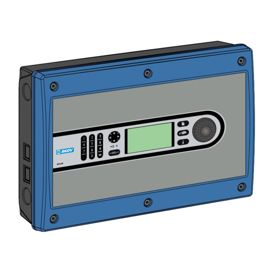
Page 78: Technical Data
Dimensions DOL 339 H x W x D: 381 x 568 x 170 mm Dimensions DOL 339 crated H x W x D: 421 x 608 x 230 mm Shipment weight DOL 339 10,7 kg DOL 339 Climate and Production Computer... - Page 80 SKOV A/S • Hedelund 4 • Glyngøre • DK-7870 Roslev Tel. +45 72 17 55 55 • Fax +45 72 17 59 59 • www.skov.com • E-mail: skov@skov.dk...
Need help?
Do you have a question about the DOL 339 and is the answer not in the manual?
Questions and answers