Table of Contents
Advertisement
Advertisement
Table of Contents

Subscribe to Our Youtube Channel
Summary of Contents for GOM ARAMIS
- Page 1 Precise Industrial 3D Metrology ARAMIS User manual hardware ARAMIS Adjustable SRX...
-
Page 2: Legal Notes
GOM. GOM reserves the right to revise this publication and change contents from time to time without obligation on the part of GOM to provide noti‐ fication of such revision or change. -
Page 3: Table Of Contents
11.1 Cabling of ARAMIS Adjustable....52 Adjust Measuring Distance....22 11.1.1 Cabling of ARAMIS Adjustable SRX..52 Adjust Slider Distance......22 Adjust the Camera Tilt Angle....25 Declaration of Conformity...... 55 Adjust the Camera Angle......27 12.1... - Page 4 0000001503_002_EN_02-12-2019 Page 4 (56)
-
Page 5: Important Notes
Important Notes Standard Signal Words In this publication the following standard signal words can be used: DANGER ▶ The label points to an imminent danger. The situation can lead to seri‐ ous bodily harm or death! WARNING ▶ The label points to a dangerous situation. The situation can lead to serious bodily harm or death! CAUTION ▶... - Page 6 Important Notes CAUTION The power cord connections must comply with the valid regulations of the respective countries. ▶ Always connect the supply voltage technically and legally correct! ▶ Always connect the devices according to the country regulations! CAUTION The local supply voltage must be within the operating voltage range of the device! An incorrect operating voltage can cause malfunctions or the risk of fire.
-
Page 7: Introduction
For operating the system optimally, the ability to visualize in 3D and a color vision ability are assumed. This user manual gives you a short overview of the measuring system ARAMIS. It contains information on: System parts of the sensor •... -
Page 8: Brief Introduction To The Aramis System
Precise 3D coordinates are captured and then metrologically evaluated. With ARAMIS, you can also measure in 2D. Then, you capture the images for the measurement series with only one camera. Thus, you get the possibility to capture images, for example, in a narrow neighborhood or through thick window panes. -
Page 9: Typical Measuring Procedure
Typical Measuring Procedure You can position the ARAMIS Adjustable system freely on a stand. If you use a 3D measuring setup, use two cameras (stereo setup). You must cali‐ brate both cameras before measuring. You create the measuring project in the software. -
Page 10: System Overview
System Overview Important Features The ARAMIS Adjustable SRX system is a measuring system that consists of modules. Not all components that are listed must be part of the scope of delivery. The following primarily describes a fully equipped system for 3D applications. - Page 11 Camera resolution [pix‐ 4096 x 3068 els] Ambient conditions +5 °C to +40 °C (non-condensing) Voltage range (typical) Supply voltage via GOM Testing Controller Power consumption Typically 15 W per camera Connection camera to 10 GigE Maximum cable length 10 m between sensor and PC Tab.
-
Page 12: Definition Of Terms
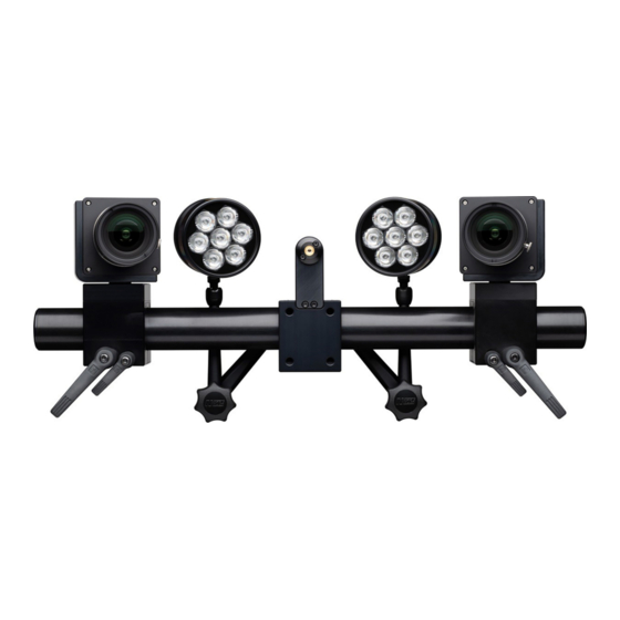
System Overview Definition of Terms Fig. 2: The figure shows a 3D sensor unit in top view. Height H (measuring vol‐ Camera angle ume) Camera lens left L Length L (measuring vol‐ Camera lens right R ume) Camera support Width W (measuring vol‐ Slider left ume) Slider right... -
Page 13: Defined Measuring Volumes
Thus, you can measure objects with different sizes at different distances. Info GOM recommends to comply with the given camera angle of 25°. For many applications, defined measuring volumes with preadjusted cam‐ era lenses are available (see 4.4.1 Defined Measuring Volumes). -
Page 14: Further Configuration Examples
CC20/MV500 1396 1200 1170 x 940 x 940 CC20/MV1400 Tab. 2: ARAMIS Adjustable SRX 4.4.2 Further Configuration Examples The sensor configuration table Fig. 3 shows how to set up different meas‐ uring volumes with a set of camera lenses. 0000001503_002_EN_02-12-2019... - Page 15 System Overview Fig. 3: Sensor configuration examples 0000001503_002_EN_02-12-2019 Page 15 (56)
-
Page 16: Control Elements
Control Elements Lenses The lenses shown in this example can, in some cases, differ from those len‐ ses delivered in practice. Then, apply the statements made here accord‐ ingly. All lenses are marked with L (left) or R (right). The terms left and right result from the sensor view in normal operating position. -
Page 17: Handling Of Tommy Screws
Control Elements NOTICE ▶ Avoid that the cameras get dirty from inside! ▶ Equip the cameras with lenses or blind caps even when they are switched off! ▶ When you change lenses, immediately insert the new lenses! Handling of Tommy Screws Each camera slider is equipped with a large and a small tommy screw. - Page 18 Control Elements NOTICE The camera support consists of aluminum. The thread of the camera locking screws can strip off at high torques. ▶ Observe the listed torque for the camera locking screws! 0000001503_002_EN_02-12-2019 Page 18 (56)
-
Page 19: Wireless Remote Control
Wireless Remote Control The ARAMIS system is delivered with a wireless remote control. Accessories Description Wireless remote control With the remote control, you can capture calibration images without using the mouse or keyboard. Receiver for the wireless remote control In the shipping configuration, the receiver is inserted in the wireless remote control. -
Page 20: Explanation Of The Function Keys
Wireless Remote Control Explanation of the Function Keys Key, Key Press: Function: You switch the remote control on or off. Using the function Capture images, you can trigger image acquisitions during the calibration. You can open the dialog Start Measur‐ Sequence. -
Page 21: Set Up Sensor
Info The cameras are preassembled to the camera mount. The screw tighten‐ ing torque is 1.1 Nm. Set Up Sensor with Software Start the GOM software. Set up the ARAMIS sensor in workspace 0000001503_002_EN_02-12-2019 Page 21 (56) -
Page 22: Adjust Measuring Distance
Set Up Sensor Fig. 6: Workspace Set Up in the software Using the icon Set Up Sensor, you can register the requested sensor and the measuring volume in the software. Adjust Measuring Distance Position the sensor at the measuring distance in front of your measuring object or the calibration object. - Page 23 Set Up Sensor Procedure: 1. Loosen the large handle. The cameras can be moved in radial direction in a limited way. Fig. 7: Loosening the large handle of the camera slider 2. Loosen the small handle. The cameras can be moved in all directions. Fig.
- Page 24 Set Up Sensor Fig. 9: Moving the cameras to the required slider distance 4. Switch on the laser pointers via the software. In the live view of the respective camera, roughly adjust the horizontal and the vertical line of the cross hairs to the projected laser point. Lock this position by means of the small handle.
-
Page 25: Adjust The Camera Tilt Angle
Set Up Sensor Adjust the Camera Tilt Angle Requirements: During the adjustment of the slider distance, you already roughly • adjusted the tilt angle. The large handle is not yet fixed. • Procedure: 1. To adjust the horizontal position of the camera, use the fine-adjust‐ ment screw. - Page 26 Set Up Sensor Fig. 13: Center position of the small handle NOTICE You cannot screw the fine-adjustment screw in a second time. ▶ Never completely remove the fine-adjustment screw. 0000001503_002_EN_02-12-2019 Page 26 (56)
-
Page 27: Adjust The Camera Angle
Set Up Sensor Adjust the Camera Angle Adjust the cameras to the projected laser point in the live view. Camera angle α results from the camera distances we adjusted in the previous sec‐ tion. If the live view is too dark or not clear, first adjust the camera lenses with focus and aperture to optimum image impression. -
Page 28: Lock Cameras
Set Up Sensor 3. Rotate the respective camera (see Fig. 14). Pay attention to the posi‐ tion of the laser point to the vertical line of the cross hairs. In the live view, the projected laser point must be adjusted to the vertical line of the cross hairs (see Fig. -
Page 29: Adjust The Aperture
Set Up Sensor Info A small aperture value means that the aperture is opened to its maximum. A large aperture value represents a closed aperture. The more the aperture is closed, the larger is the depth of field. The depth of field is the area surrounding the focus point, which is also displayed in sharp focus. - Page 30 Set Up Sensor Fig. 18: False color representation of the live view of the left and right camera 0000001503_002_EN_02-12-2019 Page 30 (56)
-
Page 31: Specimen Lighting (Option)
Specimen Lighting (Option) As specimen lighting, two types of LED lamps are available: LED lamp with a beam angle of 10° for camera lenses with a focal • length of 75 mm LED lamp with a beam angle of 30° for camera lenses with a focal •... - Page 32 • Use setup sheet C for an optimal adjustment of the polarizing filters. Position setup sheet C centrally in front of the ARAMIS Adjustable sen‐ sor within the measuring distance. Procedure: 1. Switch on the LED specimen lighting.
-
Page 33: Sensor Warm-Up
Sensor Warm-Up Before you use the ARAMIS Adjustable system for a measurement or exe‐ cute a calibration, the sensor must warm up to its operating temperature. After you switched on the sensor, a warm-up time of 20 minutes is required. -
Page 34: Calibrate The Sensor
Check the measuring distance. Ensure that the measuring distance is appropriate both between the calibration object and the camera and between the measuring object and the camera. For the ARAMIS Adjustable measuring volumes, different calibration objects are available. Fig. 20: Calibration panel CP40 with magnetic support (e.g. for MV170) -
Page 35: How To Handle Calibration Objects
Calibrate the Sensor Fig. 21: Calibration panel CP40 in the case (e.g. for MV320) Fig. 22: Calibration cross CC20, e.g. for MV1400 NOTICE Inappropriate calibration objects can affect the measuring accuracy. ▶ For calibrating, only use the calibration object which is intended for the measuring volume! 10.1 How to Handle Calibration Objects... -
Page 36: Calibration Conditions
The measuring object defines the measuring volume and thus the set • of lenses to be used. GOM delivers a calibration object with each measuring volume. The calibration object is a calibration panel or a calibration cross according to the measuring volume. - Page 37 Calibrate the Sensor Fig. 24: Temperature measurement at transport case of the calibration panel (calibration panel remains in case) 0000001503_002_EN_02-12-2019 Page 37 (56)
-
Page 38: Calibrate Sensor With Calibration Panel Cp40
10.3 Calibrate Sensor with Calibration Panel CP40 This section describes the calibration using the calibration panel CP40 with the ARAMIS Adjustable sensor on a stand. There are two types of this calibration panel: For large measuring volumes in a case •... - Page 39 Fig. 26: Calibration object CP40 in the case (without case cover) Calibration panels of the type CP40 consist of black points on a white background. The larger points in the middle inform the ARAMIS Professional software about the calibration panel type, for example, cali‐...
-
Page 40: Handling Instructions For The Calibration Panel Cp40
NOTICE You probably cannot calibrate successfully with a dirty or damaged cal‐ ibration panel. The GOM software might not recognize dirty or damaged calibration pan‐ els. ▶ Do not soil or damage particularly the area around the larger calibra‐... -
Page 41: Load Calibration Data
When you use a measuring volume for the first time, calibrate it first. Import the corresponding calibration data into the software. If you pur‐ chased the measuring volume together with the complete ARAMIS sys‐ tem, the calibration data is already loaded. - Page 42 Calibrate the Sensor Fig. 28: Exposure setting for calibration Follow the nine calibration steps and place the calibration panel in the defined positions to the sensor. You have to rotate and tilt the calibration panel from time to time. The software informs you about the individual positions in the measuring volume.
-
Page 43: Calibration Result
Show Calibration Information. ► 10.6 Calibrating ARAMIS Sensor with Calibration Cross CC20 This section describes the calibration using a calibration cross. Info As the calibration cross is large, you can only calibrate the sensor horizon‐ tally. Position the sensor horizontally and mount the calibration cross on a stand. -
Page 44: Handling Instructions For Calibration Cross Cc20
To carry out an exact calibration, observe a short rest period until the next calibration after each reposition‐ ing. Info GOM delivers a corresponding calibration object with each measuring vol‐ ume. Only use the calibration object belonging to the measuring volume. 0000001503_002_EN_02-12-2019 Page 44 (56) -
Page 45: Load Calibration Data
4. Enter the data from the certificate of the calibration cross. The calibration data is available in the software. Info If the data of the calibration object are already in the ARAMIS Professional Software, select the corresponding calibration object in step 3. NOTICE If you enter wrong calibration object data into the software, the meas‐... -
Page 46: Prepare The Calibration
Position Calibration Cross Procedure: 1. Place the calibration cross in front of the ARAMIS sensor. 2. Position the ARAMIS sensor at the measuring distance using the stand. 3. Move the stand until the two laser points merge to one common point. - Page 47 Calibrate the Sensor Single steps for calibrating the ARAMIS sensor using a calibration cross Steps for the coded calibration cross Step 1: Step 2: • Center of the measuring volume • Center of the measuring volume Cross position 45° Cross position 135°...
- Page 48 Calibrate the Sensor Steps for the coded calibration cross Step 7: Step 8: • Closer to the ARAMIS sensor • Further away from the ARAMIS sensor Cross position 315° • • Cross position 315° Step 9: Step 10: Left camera normal Left camera normal •...
- Page 49 Calibrate the Sensor Steps for the coded calibration cross Step 13: Step 14: • Center of the measuring volume • Left camera normal Cross position 270° Cross position 0° • • Step 15: Step 16: Left camera normal Left camera normal •...
-
Page 50: Calibration Result
Calibrate the Sensor Steps for the coded calibration cross Step 19: Step 20: • Right camera normal • Right camera normal Cross position 0° Cross position 90° • • Step 21: Step 22: Right camera normal Right camera normal • •... - Page 51 Calibrate the Sensor If the calibration result is insufficient, repeat the calibration and check the sensor settings and the correct camera lenses. Ensure that the cameras and lenses are mounted tight. You also reach the calibration result with Acquisition Sensor Calibra‐...
-
Page 52: Cabling
Follow the starting sequence of the individual components to ensure a functioning system. Start the measuring computer. • Start the GOM Testing Controller. The cameras are started via the • GOM Testing Controller. The GOM Testing Controller transmits the rel‐ evant signals to the sensor connection hub. - Page 53 Cabling Fig. 32: Sensor with lighting, GOM Testing Controller and PC 0000001503_002_EN_02-12-2019 Page 53 (56)
- Page 54 Cabling Fig. 33: Sensor with lighting, GOM Testing Controller and notebook Optional sensor components: Lighting control • Laser pointer • 0000001503_002_EN_02-12-2019 Page 54 (56)
-
Page 55: Declaration Of Conformity
Declaration of Conformity 0000001503_002_EN_02-12-2019 Page 55 (56) -
Page 56: Wording Of The Original Declaration Of Conformity
GOM GmbH Schmitzstraße 2 38122 Braunschweig Germany Herewith we declare that the following product Model: ARAMIS Adjustable Function: Optical deformation measuring system Serial Number: 18-000001 - 28-000001 conforms to the provisions of the following EC Directives including all applicable changes: Low voltage directive (2014/35/EU) •...
Need help?
Do you have a question about the ARAMIS and is the answer not in the manual?
Questions and answers