Table of Contents
Advertisement
Quick Links
Advertisement
Table of Contents

Related Manuals for Arkray SPOTCHEM D-00 QR


Summary of Contents for Arkray SPOTCHEM D-00 QR
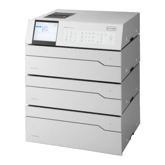
- Page 2 It is recommended to retain this operating manual for future use. The SPOTCHEM D-00 QR (SD-9811) control unit is intended for the operation of SD-3810, SD-4810 and SD-4820, which are intended for the quantitative and automated measurement of several physiological markers in whole blood, serum, and plasma.
- Page 3 ©2020 ARKRAY, Inc. • It is strictly prohibited to copy any part of this operating manual without the expressed consent of ARKRAY, Inc. • The information in this operating manual is subject to change without notice.
- Page 4 Symbols The following symbols are used in this operating manual and labels on this instrument to call your attention to specific items. For the meaning of symbols indicated on the labels (including the shipping box) not described below, refer to the leaflet included in the package.
- Page 5 This operating manual describes the necessary operations for and how to make the various settings for taking measurements. * There is also a 2D code type operation unit, SPOTCHEM D-00 QR. However, both units are described as “D-00” in this manual.
- Page 6 Caution Labels This instrument has several caution labels on the areas that have potential dangers. Please learn potential dangers warned by each label and observe the precautions described below. Rear side Power input terminal This is the power cord connector. Use the included power cord to prevent electrical shock and fires.
-
Page 7: Table Of Contents
Table of Contents Chapter 1 Before Use ..........1-1 1-1 Overview . - Page 8 Chapter 3 Connecting Existing Models ......3-1 3-1 Existing Models that Can be Connected ..... . . 3-2 3-2 Connection .
- Page 9 Chapter 5 Maintenance ..........5-1 5-1 Disinfection .
- Page 10 Chapter 1 Before Use This chapter describes what should be known before using this instrument. Overview ............1-2 1-1-1 Features .
-
Page 11: Chapter 1 Before Use
Can be connected to existing models This instrument can connect to SPOTCHEM D-Concept Series measurement units as well as other existing units made by ARKRAY to check and print the measurement results. Space-saving This instrument can connect to up to 3 measurement units stacked on top of each other. This allows the functions of 3 units to be used in the footprint for 1 unit and provides more efficient use of space. -
Page 12: Specifications
58-mm-wide printing paper printer Data storage capacity Measurement results: 100 measurements for each connected device (Maximum 300 measurements) Trouble list: 50 records for each connected device including the SPOTCHEM D-00 QR (Maximum 200 records) External output RS-232C (EIA-574) 1 port... -
Page 13: Unpacking
NOTE: For reagents and consumables used for measurement, refer to the manual of each measurement unit. 1-2-1 Instrument Items included Description Quantity Instrument SPOTCHEM D-00 QR 1-2-2 Accessories Power cord 2D code reader Printing paper Operating manual List of errors/troubles... -
Page 14: Accessories Packing Box
1-2 Unpacking 1-2-3 Accessories Packing Box Blower brush Philips screwdriver Hexagonal wrench Item Name Description Quantity Blower brush Used for the measurement unit maintenance. Philips screwdriver Used for the measurement unit maintenance. Hexagonal wrench Used for the measurement unit installation. This blower brush contains natural rubber latex which may cause allergic reactions. -
Page 15: Part Names And Functions
Chapter 1 Before Use Part Names and Functions 1-3-1 Front Side of Instrument Item Name Function Display Displays instrument operation status, measurement results, errors etc. Operator panel Contains the buttons for operating the instrument, such as for measurement start and numerical entry. For details, see “1-4 Operator Panel”... -
Page 16: Rear Side Of Instrument
2 (Ethernet) connection. For details, see “When connecting external devices” (page 1-7). When connecting external devices NOTE: Use the communication cable specified by ARKRAY when connecting the instrument to external devices. For details, please contact your local distributor. D-00 QR... -
Page 17: Operator Panel
Chapter 1 Before Use Operator Panel All SPOTCHEM D-Concept measurements are performed from the instrument’s operator panel. This section explains the names and functions of the buttons on the operator panel. 10 12 13 11 Item Symbol Function (None) Shows the instrument status and setting information. For details, see “2-1 Screens” (page 2-2). Press one of these buttons to select a measurement unit (or existing model). - Page 18 1-4 Operator Panel Item Symbol Function Press this button to confirm the setting information. Press this button to transfer the measurement results to the connected external device if any. Press this button to turn the power on/off during normal use. Lights up blue when the power is turned on.
-
Page 19: Measurement Unit Connection And Display
Chapter 1 Before Use Measurement Unit Connection and Display The connecting terminals ( ) on the rear side of this instrument connected to a measurement unit (or existing model) correspond to the buttons on the operator panel. The on-screen position of the measurement unit connected to this instrument is determined by the connected terminals. -
Page 20: Installation
1-6 Installation Installation 1-6-1 Precautions for Installation Before installing the instrument, read the following items and always take proper safety precautions. Install the instrument under the supervision of a serviceperson. • Determine a location for the instrument and assemble it in that location. Do not move the instrument with the measurement unit or external device connected. -
Page 21: Precautions For Moving The Instrument
Chapter 1 Before Use 1-6-2 Precautions for Moving the Instrument When moving the instrument, read the following items and always take proper safety precautions. • Be sure that the operation unit is not connected to the instrument. • Hold the handles with both hands and be careful not to apply any shock or vibration to the instrument while moving it. - Page 22 Chapter 2 Basic Operation This chapter describes the basic operations of the instrument. Screens ............2-2 2-1-1 Status Indication Screen .
-
Page 23: Chapter 2 Basic Operation
Chapter 2 Basic Operation Screens This section explains the major types of screens displayed by the instrument. 2-1-1 Status Indication Screen This is the basic screen of the instrument. This screen is displayed after the instrument has been turned on (press the button) and startup process is completed. -
Page 24: Setting Screen
2-1 Screens 2-1-3 Setting Screen The setting screen is used to set the parameter selected on the Menu screen. 2-1-4 Message Screen A message pops up to prompt you to confirm some specific operation or other issues. D-00 QR... -
Page 25: Menu Screen Operation
Chapter 2 Basic Operation Menu Screen Operation All SPOTCHEM D-Concept operations are performed from the instrument’s operator panel. The explanation given here uses the [Main menu] screen as an example to explain the basic operation method. Moving menus Select menu to display the settings screen In the [Main menu] screen and [Sub menu] screen, each menu item has a number shown on the left, press the numeric buttons ([1] to [9] buttons) corresponding to the item. -
Page 26: Setting Screen Operation
2-3 Setting Screen Operation Setting Screen Operation 2-3-1 Setting Screen Operation Cursor On a setting screen, you may be prompted to select a highlighted item or to enter in the blinking digit or field. There is a cursor on the highlighted item or digit. Cursor ... -
Page 27: Changing Set Values
Chapter 2 Basic Operation 2-3-2 Changing Set Values Items enclosed by [ ] can be changed to the names or set values preprogrammed in the instrument. With the cursor positioned at the item, press the [ ] button to change the name or value. Press the button. -
Page 28: Moving The Cursor
2-3 Setting Screen Operation Moving the cursor To enter the same character repeatedly, such as “AA”, enter the second character after first moving the cursor. Enter the first character. Press the [ ] button. The cursor moves to the right. Enter the second character. -
Page 29: Entering Numbers
Chapter 2 Basic Operation 2-3-4 Entering Numbers This section explains how to enter numbers, such as measurement numbers. In the field to enter only numbers, the cursor blinks at the rightmost digit. Use the numeric buttons ([0] to [9] buttons). (Ex.) When entering “1302”... -
Page 30: Entering Time
2-3 Setting Screen Operation Enter the day. Enter “2” and “3”. REFERENCE: To enter two different dates, such as a start date and an end date, press the button to move the cursor from the first date field to the second field. 2-3-6 Entering Time Hour... -
Page 31: Message Screen Operation
Chapter 2 Basic Operation Message Screen Operation A message prompting confirmation sometimes pops up during measurement or setting operation. Read the message and press the appropriate button to continue the operation. D-00 QR 2-10... -
Page 32: Operation When An Error Occurs
2-5 Operation when an Error Occurs Operation when an Error Occurs If an error occurs during operation, the following screen will pop up. Read the message and take the correct measures. For details on operation at the error, see “Chapter 6 Troubleshooting” (page 6-1). - Page 33 Chapter 2 Basic Operation D-00 QR 2-12...
- Page 34 Chapter 3 Connecting Existing Models This chapter describes connecting existing models to this instrument and gives an overview of operation. Existing Models that Can be Connected ......3-2 Connection .
-
Page 35: Chapter 3 Connecting Existing Models
Existing Models that Can be Connected This instrument can be connected to up to 3 measurement units or existing models made by ARKRAY. This instrument starts and stops measurement operations by the connected models and displays and prints out their measurement results. -
Page 36: Connection
NOTE: Use the following procedure to turn on the power when connected to existing models. Starting up in incorrect order may cause trouble. Turn on the SPOTCHEM D-00 QR. After the status indication screen is displayed, turn on the existing model(s). -
Page 37: Operation And Results Check
Chapter 3 Connecting Existing Models Operation and Results Check 3-3-1 Measurement Operation This instrument starts and stops measurement operation of the connected existing model. In this section, explanation is made on the SP-4430 as the sample. Check that the existing model is in standby and press the button. -
Page 38: Display Of Results
3-3 Operation and Results Check 3-3-2 Display of Results The measurement results of existing models connected to this instrument are displayed as shown below. When there are multiple pages, press the button to go to another page. SP-4430 SI-3510 / SI-3511 ... -
Page 39: Printing Of Results
Chapter 3 Connecting Existing Models 3-3-3 Printing of Results You can print out and check the measurement results. This section explains how to read the printed measurement results. SP-4430 Item Description Unit name Measurement date and time Measurement number Sample ID Printing is available only when the ID is entered. - Page 40 3-3 Operation and Results Check Item Description Multiple reagent item name and Printed only when this reagent is used. measurement result The following are printed depending on the measurement value. : The value is higher than the normal range : The value is lower than the normal range OVER: The value is higher than the measurable range UNDER: The value is lower than the measurable range The upper or lower limit of the measurement range is printed after...
- Page 41 Chapter 3 Connecting Existing Models SI-3510 / SI-3511 Item Description Unit name Measurement date and time CH number Sample type Measurement number Sample ID Printed only when this reagent is used. Reagent name Reagent lot number Item name and measurement The following are printed depending on the measurement value.
- Page 42 3-3 Operation and Results Check SE-1520 Item Description Unit name Measurement date and time Sample type Measurement number Sample ID Printed only when this reagent is used. Electrolyte plate reagent name Electrolyte plate lot number Electrolyte plate item name and The following are printed depending on the measurement value.
- Page 43 Chapter 3 Connecting Existing Models D-00 QR 3-10...
-
Page 44: Chapter 4 Menu Operations
Chapter 4 Menu Operations This chapter describes the items that can be set at the instrument’s menu screens and the operation method. Menu Screen Overview ......... . 4-2 ... -
Page 45: Menu Screen Overview
Chapter 4 Menu Operations Menu Screen Overview On the status indication screen, press [0] to display the [Main menu] screen. Through the menu screen, the instrument’s settings and measurement results can be accessed and the operations necessary for maintenance can be performed. This section explains the items that can be set at the instrument’s menu screens and the reference pages. -
Page 46: Entering The Measurement Number
4-2 Entering the Measurement Number Entering the Measurement Number Enter the measurement number that is used for the respective measurement units. The measurement number is input as a 4-digit number. REFERENCE: For details on entering numeric values, see “2-3-4 Entering Numbers” (page 2-8). Press [1] on the [Main menu] screen. -
Page 47: Entering The Sample Id
Chapter 4 Menu Operations Entering the Sample ID Enter the sample ID that is used for the respective measurement units. Sample ID restrictions For the sample ID, enter up to 18 alphanumeric characters or symbols. REFERENCE: For details on entering characters, see “2-3-3 Entering Characters” (page 2-6). The number of sample IDs that can be entered differs depending on the connected measurement unit. - Page 48 4-3 Entering the Sample ID Press [2] on the [Main menu] screen. REFERENCE: You can also press [2] on the status indication screen to display the <Sample ID> screen. At the <Sample ID> screen, press the button(s) to select the measurement unit(s) to enter the Sample ID. REFERENCE: •...
-
Page 49: Measurement Results
Chapter 4 Menu Operations Measurement Results The measurement results stored in the instrument memory can be printed or output to an external device when necessary. In addition, the information displayed on the screen can be checked. 4-4-1 Search for Measurement Results ... -
Page 50: Using Wildcards
4-4 Measurement Results Using wildcards You can enter wildcard characters for sample ID search. Character Used Meaning Shows any character string of the 0 or more characters. Shows any 1 character. These characters can be used to enter the search criteria as in the examples shown below. Examples of Entry Meaning Searches all sample IDs. - Page 51 Chapter 4 Menu Operations Press the button(s) of the measurement unit(s) to be searched. REFERENCE: • More than one measurement units can be selected. • Press the buttons again to cancel the selection. Set the search results order. Press the [ ] button to select the order and then press the button.
-
Page 52: Checking And Printing Measurement Results
4-4 Measurement Results Start the search After all the conditions have been entered, press the button. REFERENCE: For details on checking and printing search result, see “4-4-2 Checking and Printing Measurement Results” (page 4-9). 4-4-2 Checking and Printing Measurement Results You can do the following things when the measurement result list is retrieved based on your search criteria. - Page 53 Chapter 4 Menu Operations Button Function Press this button to delete the selected measurement results. Press this button to print the selected measurement results. Press this button to send the selected measurement results to an external device. Use these buttons to turn the search result pages. Press this button to return to the previous screen.
- Page 54 4-4 Measurement Results Press the button to check the measurement result details. Press the button to return to the <Measurement results> list screen. Print the selected measurement results In the <Measurement results> list screen, press [2] or [8] and move the cursor to the measurement results to be printed.
- Page 55 Chapter 4 Menu Operations Delete the selected measurement results from memory In the <Measurement results> list screen, press [2] or [8] and move the cursor to the measurement results to be deleted. Press [5] to highlight the selection. REFERENCE: To select all the measurement results, press [3]. Press the button.
- Page 56 4-4 Measurement Results Transfer the selected measurement results to an external device In the <Measurement results> list screen, press [2] or [8] and move the cursor to the measurement results to be transferred. Press [5] to highlight the selection. REFERENCE: To select all the measurement results, press [3].
-
Page 57: Sub Menus
Chapter 4 Menu Operations Sub Menus 4-5-1 Clock Adjustment This adjusts the instrument built-in clock. The date and time might be incorrect after instrument installation or non-use for a long period of time. The date and time for screen display and printing depends on the built-in clock, so set the date and time correctly. -
Page 58: Option Settings
4-5 Sub Menus Set the date and time Enter the [Date] and [Time]. REFERENCE: For details on entering the date and time, see “2-3-5 Entering Date” (page 2-8) and “2-3-6 Entering Time” (page 2-9). Press the button. This returns to the [Parameter settings] screen. - Page 59 Chapter 4 Menu Operations Display the <Option setting> screen Press [4] on the [Main menu] screen. Press [1] on the [Sub menu] screen. Press [2] on the [Parameter settings] screen. D-00 QR 4-16...
- Page 60 4-5 Sub Menus Set the option items Set the items. REFERENCE: Enter the characters for [Unit name] and [Patient type]. For details on entering characters, see “2-3-3 Entering Characters” (page 2-6). Press the button. This returns to the [Parameter settings] screen.
-
Page 61: Option Setting Initialization
Chapter 4 Menu Operations 4-5-3 Option Setting Initialization This returns all of the changed option setting items to their default settings. Press [4] on the [Main menu] screen. Press [1] on the [Sub menu] screen. Press [3] on the [Parameter settings] screen. A message appears prompting a confirmation of initializing the information. -
Page 62: Trouble List Search
4-5 Sub Menus 4-5-4 Trouble List Search The past errors and trouble history can be retrieved as a list. This section explains how to retrieve the desirable record(s) from the trouble history. Maximum number of cases to be stored in the memory Each measurement unit can store up to 50 error/trouble records. - Page 63 Chapter 4 Menu Operations Display the <Trouble list> screen Press [4] on the [Main menu] screen. Press [2] on the [Sub menu] screen. Set the search items Set the search criteria. Press the buttons to select the measurement unit in which search will be performed.
- Page 64 4-5 Sub Menus Set the search results order. Press the [ ] button to select the order and then press the button. Set the period of time. Enter the first and end dates, and press button. REFERENCE: For details on entering the date, see “2-3-5 Entering Date” (page 2-8).
-
Page 65: Checking And Printing Trouble List
Chapter 4 Menu Operations 4-5-5 Checking and Printing Trouble List From trouble list obtained as the result of the search by the criteria, you can do the following things: • Check the errors and trouble on the screen • Print the selected error or trouble •... - Page 66 4-5 Sub Menus Button Function Press this button to delete the selected record(s). Press this button to print the selected history information. Use these buttons to turn the search result pages. Press this button to return to the previous screen. Press this button to print the selected history information at the cursor position.
- Page 67 Chapter 4 Menu Operations Print the selected records In the <Trouble list> screen, press [2] or [8] to move the cursor to the records to be printed. Press [5] to highlight the selection. REFERENCE: To select all the records, press [3]. Press the button.
- Page 68 4-5 Sub Menus Delete the selected records from memory In the <Trouble list> screen, press [2] or [8] to move the cursor to the records to be deleted. Press [5] to highlight the selection. REFERENCE: To select all the records, press [3]. Press the button.
-
Page 69: Turning On/Off Measurement Unit
Chapter 4 Menu Operations 4-5-6 Turning On/Off Measurement Unit This turns on/off the connected measurement unit. REFERENCE: This instrument cannot turn on/off the connected existing models. Display the [Maintenance] screen Press [4] on the [Main menu] screen. Press [3] on the [Sub menu] screen. Turn the power On/Off To turn off the measurement unit, select “1 Power Off,”... -
Page 70: Chapter 5 Maintenance
Chapter 5 Maintenance This chapter describes the procedure of maintenance. Disinfection ............5-2 Setting the Printing Paper . -
Page 71: Disinfection
Chapter 5 Maintenance Disinfection If a sample is attached, clean it by following the instructions below. For disinfection of the device, lightly wipe the disinfecting area with a cotton swab or gauze moistened with a disinfectant, then wipe the disinfectant with a cotton swab or gauze moistened with water, and then wipe it dry. Use 70% isopropanol as the disinfectant. -
Page 72: Setting The Printing Paper
• Do not place the printing paper near a heater or other heat sources. In addition, store it away from chemicals, such as alcohol. Heat or chemicals may blacken the paper and prevent printing. • Only use the printing paper specified by ARKRAY. Using any other printing paper may cause the instrument to malfunction. - Page 73 Chapter 5 Maintenance Load the new printing paper Hold the new printing paper in the direction shown in the figure and load it into the printer. Pull out the end of the printing paper by several centimeters. Close the printer cover. Tear off the paper that has been pulled out.
- Page 74 Chapter 6 Troubleshooting A message is displayed when trouble occurs with the instrument. This chapter describes the meaning of these messages and troubleshooting methods. Message Types ..........6-2 Warning Messages .
-
Page 75: Chapter 6 Troubleshooting
Chapter 6 Troubleshooting Message Types A trouble message appears on the display when the instrument has a problem. There are three levels of such messages based on the severity of the problem. Message type Description Warning Displayed as “W-00XX”. Follow the displayed message to solve the problem. If the message is repeatedly displayed, turn off the instrument and contact your local distributor. -
Page 76: Warning Messages
6-2 Warning Messages Warning Messages W-0001 Cause Possible solution The printing paper has run out. Check the printer inside and load the new printing paper. For details, see “5-2 Setting the Printing Paper” (page 5-3). If the paper runs out during printing, a message appears asking if you want to reprint. - Page 77 Chapter 6 Troubleshooting W-0004 Cause Possible solution A different type of 2D code was read. Enter the correct information. W-0005 Cause Possible solution The Reagent Info. has some problem. Check if the Reagent Info. is damaged or dirty. W-0006 Cause Possible solution A problem occurred in the instrument Correctly reconnect the connecting cable of the measurement unit.
-
Page 78: Error Messages
6-3 Error Messages Error Messages E-0101/E-0102/E-0103 Cause Possible solution The instrument program version has been Press the button to cancel the error. upgraded. E-0104 Cause Possible solution The connecting cable between the instrument Press the button to cancel the error. and the measurement unit is disconnected. - Page 79 Chapter 6 Troubleshooting E-0108 Cause Possible solution The existing model is not turned on. Press the button to cancel the error. Turn off and on the existing model to check the status. The cable is not connecting this instrument and Press the button to cancel the error.
-
Page 80: Trouble Messages
6-4 Trouble Messages Trouble Messages T-0201 to T-0999 Cause Possible solution An internal malfunction occurred. Press the button to cancel the error. Turn off the power and contact your local distributor. D-00 QR... - Page 81 Chapter 6 Troubleshooting D-00 QR...
-
Page 82: Index
Chapter 7 Index Index ............7-2 D-00 QR... - Page 83 Chapter 7 Index Index ...1-10 Measurement unit connection and display ........4-26 Measurement unit power ............4-2 ............1-4 Menu screen Accessories .........2-4 .......1-4, 1-5 Menu screen operation Accessories packing box ........2-3, 2-10 ............4-2 Message screen Adjustments ..........1-6, 1-8 ..
Need help?
Do you have a question about the SPOTCHEM D-00 QR and is the answer not in the manual?
Questions and answers