Advertisement
Quick Links
Assembly instructions for the pump and control
EN
unit ZPS 18e-01 ECO
1
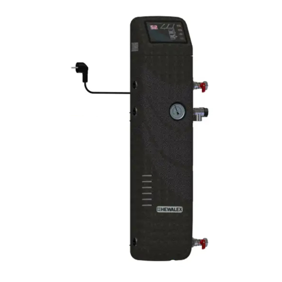
USE AND CONSTRUCTION OF THE PUMP AND CONTROL UNIT ZPS 18E-01
The ZPS pump and control unit is designed to work with solar collectors in systems with required flow of the heat transfer fluid up to 18 l/min,
depending on the surface of the mounted solar collectors.
The ZPS pump and control unit is compacted in a foamed polypropylene cover and it contains accessories necessary for correct functioning of the
solar installation: solar circulation pump, air separator, discharge valves, check valve, shut-off valve, manometer, electronic flow meter, G-422
controller with four temperature sensors and power cable.
Diagrams and assembly drawings
Fig. 1.
ZPS 18e-01 ECO
Fig. 2.
Power cable 230V
Assembly support
Temperature sensor NTC10kW*
* Power cable 230 V and cables for temperature sensors
have the possibility to exit into the left or right side
solar collectors
T3
min. 20 cm
Hydraulic brake
11.01.2023
T1
T4
T2
water heater
ZPS 18e-01 ECO
Discharage valve + EPDM gasket
Safety valve 6bar + EPDM gasket
Plug KS 3/4 + EPDM gasket
Discharge valve + EPDM gasket
HEWALEX Sp. z o.o. Sp. k.
+48 32 214 17 10
www.hewalex.pl
1
Advertisement

Subscribe to Our Youtube Channel
Related Manuals for Hewalex ZPS 18e-01 ECO


Summary of Contents for Hewalex ZPS 18e-01 ECO
- Page 1 Assembly instructions for the pump and control HEWALEX Sp. z o.o. Sp. k. +48 32 214 17 10 unit ZPS 18e-01 ECO www.hewalex.pl USE AND CONSTRUCTION OF THE PUMP AND CONTROL UNIT ZPS 18E-01 The ZPS pump and control unit is designed to work with solar collectors in systems with required flow of the heat transfer fluid up to 18 l/min, depending on the surface of the mounted solar collectors.
- Page 2 Fig. 4. Fig. 3. Distance bracket* height 75 mm solar coil outlet collector feeding discharge valve safety valve 6 bar *Please prepare the orders separately - this bracket not constitutes an accessories expansion tank delivered normally with the ZPS18e-01 unit ASSEMBLY OF THE ZPS UNIT Consecutive steps: Attach the support of the ZPS unit to the wall using 2 anchor screws (fig.
- Page 3 Do not switch off the rotary pump until full de-aeration of the system – it means till air bubbles stop appearing in the overflow pipe. Subsequently, fully open the drain valve, to which a forcing hose is connected and observe whether air bubbles come out the overflow hose. When air bubbles stop appearing in the overflow pipe, close the upper discharge valve and continue pumping of the heat transfer fluid to the system, to reach required system overpressure of p = 2.5 bar, which is measured by the manometer.
- Page 4 Input / Output Description Communication input RS485 to connect a computer or other device 9 - 10 9....+A 10....-B PWM control input to control ST7PWM2 pump 11 - 12 11....PWM - 12....PWM + Schematic and electric diagram of the installation no. 1 Fig.
Need help?
Do you have a question about the ZPS 18e-01 ECO and is the answer not in the manual?
Questions and answers