Table of Contents
Advertisement
Installer's Guide
Convertible Air Handlers
1-1/2 – 5 Ton
Standard Coil
GAM5B0A18M11SB
GAM5B0A24M21SB
GAM5B0B30M21SB
GAM5B0B36M31SB
GAM5B0C42M31SB
GAM5B0C48M41SB
GAM5B0C60M51SB
Only qualified personnel should install and service the equipment. The installation, starting up, and servicing of heating, ventilating,
and air-conditioning equipment can be hazardous and requires specific knowledge and training. Improperly installed, adjusted or
altered equipment by an unqualified person could result in death or serious injury. When working on the equipment, observe all pre-
cautions in the literature and on the tags, stickers, and labels that are attached to the equipment.
April 2020
Black Epoxy Coil
GAM5B0A18M11EA
GAM5B0A24M21EA
GAM5B0B30M21EA
GAM5B0B36M31EA
GAM5B0C42M31EA
GAM5B0C48M41EA
GAM5B0C60M51EA
SAFETY WARNING
18-GJ04D1-15A-EN
Note: "Graphics in this document are for representation only.
Actual model may differ in appearance."
Advertisement
Table of Contents

Related Manuals for Trane Technologies GAM5B0A18M11SB


Summary of Contents for Trane Technologies GAM5B0A18M11SB
- Page 1 Installer’s Guide Convertible Air Handlers 1-1/2 – 5 Ton Standard Coil Black Epoxy Coil GAM5B0A18M11SB GAM5B0A18M11EA GAM5B0A24M21SB GAM5B0A24M21EA GAM5B0B30M21SB GAM5B0B30M21EA GAM5B0B36M31SB GAM5B0B36M31EA GAM5B0C42M31SB GAM5B0C42M31EA GAM5B0C48M41SB GAM5B0C48M41EA GAM5B0C60M51SB GAM5B0C60M51EA Note: “Graphics in this document are for representation only. Actual model may differ in appearance.”...
- Page 2 ALL phases of this installation must comply with NATIONAL, STATE AND LOCAL CODES Important: This Document is customer property and is to remain with this unit. Please return to service information pack upon completion of work. Important: These instructions do not cover all variations in systems nor provide for every possible contingency to be met in connection with the installation.
-
Page 3: Table Of Contents
Table of Contents Section 1. Safety Information........................3 Section 2. Unit Design..........................4 Section 3. Unit Preparation........................6 Section 4. Optional Cabinet Disassembly....................7 Section 5. Place Unit at Location......................11 Section 6. Unit Location Considerations....................12 Section 7. Setting the Unit - Vertical Installation...................17 Section 8. Setting the Unit - Horizontal Installation................19 Section 9. -
Page 4: Section 2. Unit Design
Section 2. Unit Design 2.1 Cabinet Penetration Important: Due to the unique design of this unit, which allows the electrical wiring to be routed within the insulation, do not screw, cut, or otherwise punc- ture the unit cabinet in any location other than the ones illustrated. - Page 5 The Coil, Line Set, and Heater panels are removed using Phillips head screws. #3 Size Phillips Coil and Heater panels must be removed prior to re- moving the Line Set panel. To remove Coil Panel: 1. Turn screws on Coil panel. 2.
-
Page 6: Section 3. Unit Preparation
Section 3. Unit Preparation 3.1 Prepare The Unit For Installation STEP 1 - Check for damage and report promptly to the carrier any damage found to the unit. Note: If the unit must be transported in a horizontal posi- tion, it must be laid on its back (marked “REAR” on carton). Note: After the unit is removed from the carton, release pressure from the coil to verify coil is pressurized and leak free. -
Page 7: Section 4. Optional Cabinet Disassembly
Section 4. Optional Cabinet Disassembly 4.1 Disassemble cabinet for installation in tight areas or as needed. Note: If the unit must be transported in a horizontal position, it must be laid on its back (marked “REAR” on carton). Note: To reassemble cabinet, follow the steps in reverse order. - Page 8 STEP 4 - Slide Blower assembly out of unit using built-in blower support channels and set aside. Note: Remove the cardboard from the bottom of the blower. Cut the tie wrap and remove the foam block located at the motor. Blower Support Channel STEP 5 - Slide Coil assembly out of unit using built-...
- Page 9 STEP 6 - Use a 5/16 Allen wrench on the locking mechanism on each side of the bottom half of the cabinet to loosen the locking mechanism. The locks loosen by turning counter-clockwise approximately 3/4 of a turn. STEP 7 - Lift the Coil section up and away from the Blower section.
- Page 10 STEP 8 - For extremely tight spaces where the cabinet needs to be rotated through a small opening, remove the top panel. Use a manual driver to avoid stripping screw holes. STEP 9 - Continue preparation by following the proper carrying procedures shown in Section 5.
-
Page 11: Section 5. Place Unit At Location
Section 5. Place Unit at Location 5.1 Carry Unit STEP 1 - Carry the unit to the installation location. STEP 2 - Reassemble by reversing the steps listed in Section 4 if disassembly was required. Important: Under no conditions should metal strap- ping be attached to the unit to be used as support mechanisms for carrying or suspension purposes. -
Page 12: Section 6. Unit Location Considerations
Section 6. Unit Location Considerations 6.1 Unit Dimensions and Weight Table 7.1 Model H x D x W *Blower Unit Number Compartment Net Weight lbs. GAM5B0A18M21SB 50 x 22 x 17 1/2 GAM5B0A18M11EA GAM5B0A24M21SB 50 x 22 x 17 1/2 GAM5B0A24M21EA GAM5B0B30M31SB 52 x 22 x 21... - Page 13 6.2 Four-Way Conversion To place the unit in the configuration your application requires (upflow, downflow, horizontal right, or horizontal left), simply turn the unit to that orientation. Note: The air handlers are shipped from the factory suitable for four-way application. Note: Entry for low voltage connections is allowed on either side of cabinet.
- Page 14 Airflow Horizontal Left Refrigerant Low Voltage Condensate Connections Connections Drains inside unit Horizontal Left Configuration Low Voltage Connections Refrigerant inside unit Connections Airflow Horizontal Right Condensate Drains Horizontal Right Configuration...
- Page 15 6.3 Non Ducted Applications CAUTION Supply Duct HAZARDOUS VAPORS! Do not install an air handler with a non-ducted return in the same closet, alcove, or utility room as a fossil fuel device. Hazard- ous vapors can be distributed throughout the condi- tioned space and equipment damage can result.
- Page 16 6.5 Additional Unit Preparation Considerations • These units are not approved for outdoor installation. For proper installation the following items must be con- sidered prior to moving the unit to its installation site: • These units must be installed in the proper air flow direction.
-
Page 17: Section 7. Setting The Unit - Vertical Installation
Section 7. Setting the Unit - Vertical Installation 7.1 Considerations Provide a minimum height of 14 inches for proper unrestricted airflow below the unit. Allow a minimum of 21 inches clearance in front of the air handler to permit maintenance and removal of filter. •... - Page 18 Plenum Installation 1. Assemble the plenum using the plenum’s Installer Guide. On units with sheet metal returns: Return plenum must be flanged. Sheet metal drill point screws must be 1/2” in length or shorter. Airflow Typical Plenum Installation 7.3 Downflow Installation •...
-
Page 19: Section 8. Setting The Unit - Horizontal Installation
Section 8. Setting the Unit - Horizontal Installation 8.1 Considerations Important: Due to the unique design of this unit, which allows the electrical wiring to be routed within the insulation, do not screw, cut, or otherwise puncture Field Supplied the unit cabinet in any location other than the ones Isolators illustrated in this Installer Guide or in an approved ac- cessory’s Installer Guide. -
Page 20: Section 9. Connecting The Duct Work
Section 9. Connecting the Duct work 9.1 Duct Connection Considerations Important: Due to the unique design of this unit, which allows the electrical wiring to be routed within the insulation, do not screw, cut, or otherwise punc- ture the unit cabinet in any location other than the ones illustrated in this Installer Guide or in an ap- proved accessory’s Installer Guide. -
Page 21: Section 10. Refrigerant Line
Section 10. Refrigerant Line 10.1 Refrigerant Line Connection Sizes Table 10.1 Refrigerant Line Set and Connection Sizes Vapor Line Liquid Line Model Connection Connection GAM5B0A18M21SB, GAM5B0A18M11EA GAM5B0A24M21SB, GAM5B0A24M21EA GAM5B0B30M31SB, GAM5B0B30M21EA GAM5B0B36M31SB, GAM5B0B36M31EA GAM5B0C42M41SB, GAM5B0C42M31EA GAM5B0C48M41SB, GAM5B0C48M41EA GAM5B0C60M51SB, GAM5B0C60M51EA Note: Refrigerant line sets should match the vapor line connection size in this table when connecting to any single stage outdoor unit. -
Page 22: Section 11. Refrigerant Line Brazing
Section 11. Refrigerant Line Brazing 11.1 Braze The Refrigerant Lines STEP 1 - Remove Heater, Coil, and Line Set panels. Heater (See Section 2.2 Panel Removal) Panel Line Set Panel Coil Panel Important: Do NOT unseal coil refrigerant connec- tion stubs until ready to make connections. Important: Heat Sensitive Bulb. - Page 23 Important: Heat Sensitive Bulb. The TXV sensing bulb must be removed or a wet rag Wet Rag on must be wrapped around the suction line between TXV sensor bulb the Bulb and the braze joint to protect the Bulb from failure due to overheating.
- Page 24 Important: Do not open the service valves until the refrigerant lines and indoor coil leak check and evacu- ation are complete. 0350 Microns STEP 8 - Evacuate until the micron gauge reads no higher than 350 microns, then close off the valve to the vacuum pump.
-
Page 25: Section 12. Condensate Drain Piping
Section 12. Condensate Drain Piping 12.1 Condensate Drain Piping Considerations • Do not use reducing fittings in the condensate • Condensate drain plumbing must comply with na- drain lines. tional, state, and local codes. • Route condensate drain lines away from air handler •... - Page 26 STEP 4 - Install a clean-out tee in the primary drain line for future maintenance. It is recom- mended that you install a cap on the top of the tee. 1.5” min. 1.5” minimum clearance is recommended from cabinet to inside edge of tubing STEP 5 - Insulate the primary drain line to...
-
Page 27: Section 13. Electrical - Low Voltage
Section 13. Electrical - Low Voltage 13.1 Low Voltage Maximum Wire Length Table 13.1 defines the maximum total length of low Table 13.1 voltage wiring from the outdoor unit, to the indoor 24 VOLTS unit, and to the thermostat. WIRE SIZE MAX. - Page 28 STEP 5 - Using field supplied wire nuts, make connections per hookup diagrams. Air Handler Hook-up Diagram 1 Stage Cooling W2 Pink W3 Brown W1 White Air Handler Air Conditioner Comfort Control White White Blue Yellow Green Green Yellow Yellow Orange Blue Blue...
- Page 29 Air Handler Hook-up Diagram 2 Stage Cooling NOTE: Airflow Speed tap W1 White adjustment is required W2 Pink W3 Brown Air Conditioner Air Handler YL/RD Comfort Control White White Green Green YL/BK Blue Yellow Yellow Purple Purple Blue Blue Field wiring •...
-
Page 30: Section 14. Electrical - High Voltage
Section 14. Electrical - High Voltage 14.1 High Voltage Power Supply WARNING The high voltage power supply must match the equipment nameplate. LIVE ELECTRICAL COMPONENTS! During installation, testing, servicing, and trouble- Power wiring, including ground wiring, must comply shooting of this product, it may be necessary to work with national, state, and local codes. - Page 31 STEP 4 - If an electric heater IS NOT being BLACK installed, remove the pigtail harness from the GREEN - GROUND documentation pack and connect it to the plug on the inside of the Heater Compartment in the cabinet. If an electric heater IS being installed, see the Installer’s Guide shipped with the electric heater.
- Page 32 STEP 6 - Reinstall all panels before starting the air handler. NOTE: After replacing all panels, loosen the Line Set Panel screws approximately 1/4 - 1/2 turn. This will improve the seal between the Heater Panel and Line Set Panel. 14.3 Secure Coil (All Applications) STEP 1 - Remove screw and coil panel bracket from documentation packet.
-
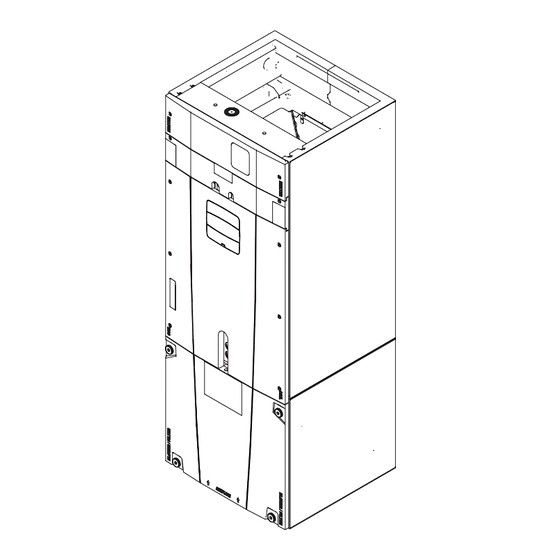
Page 33: Section 15. Unit Outline Drawing
Section 15. Unit Outline Drawing... -
Page 34: Section 16. Filters
The following combinations should be charged to 8 degrees sub-cooling to maintain ratings. degrees sub-cooling to maintain ratings. Indoor Unit Model No. Outdoor Unit Model No. Indoor Unit Model No. Outdoor Unit Model No. GAM5B0A18M11SB 4A6B4018E1 GAM5B0A18M11SB 4TWB4018E1 GAM5B0A18M11EA 4A6H5018E1 GAM5B0A18M11EA... - Page 35 17.2 System Start Up STEP 1 - Make sure all panels are securely in place and that all wiring has been properly dressed and secured. STEP 2 - Set the system thermostat to OFF. DONE CANCEL STEP 3 - Turn on electrical power disconnect(s) to apply power to the indoor and outdoor units.
-
Page 36: Section 18. Sequence Of Operation
Section 18. Sequence of Operation 18.1 Sequence of Operation GAM5 Sequence of Operation: Single Stage Heat Pump OD (heating) See unit, electric heat, and field wiring diagrams for 1. R-Y contacts close on the comfort control sending additional information. 24VAC to Y terminal on the fan relay and the Y in the outdoor unit. -
Page 37: Section 19. Checkout Procedures
Electric Heating 1. R-W contacts close on the comfort control sending 24VAC to the W terminal on the fan relay. 24VAC is also sent to EHC to energize the heat relay. 2. R-G contacts close on the comfort control send- ing 24VAC to the G terminal on the fan relay. -
Page 38: Section 20. 2-Stage Outdoor Adjustment
Section 20. 2-Stage Outdoor Adjustment 20.1 Adjustments for 2-Stage outdoor AC models 16 SEER Cooling Models OD MODEL ID MODEL SPEED TAP SYSTEM STAGE 4TTR6024A* 0.333 4TTX6024G* GAM5B0A24M21* 0.273 4A7A6024G* 4TTR6036A* 1225 0.357 4TTX6036G* GAM5B0B36M31* 1070 0.272 4A7A6036G* 4TTR6036A* 1225 0.400 4TTX6036G* GAM5B0C42M31*... - Page 39 20.2 Adjustments for 2-Stage outdoor HP models 16 SEER Heat Pump Models OD MODEL ID MODEL SPEED TAP SYSTEM STAGE 4TWR6024A*4 0.333 4TWX6024G*4 GAM5B0A24M21* 0.293 4A6H6024G* 4 4TWR6024A* 0.383 4TWX6024G* GAM5B0B30M21* 0.301 4A6H6024G* 4TWR6036A* 1150 0.500 4TWX6036E* GAM5B0B36M31* 1005 0.382 4A6H6036E* 4TWR6048A* 1375...
- Page 40 About Trane and American Standard Heating and Air Conditioning Trane and American Standard create comfortable, energy efficient indoor environments for residential applications. For more information, please visit www.trane.com or www.americanstandardair.com The manufacturer has a policy of continuous data improvement and it reserves the right to change design and specifications without notice. We are committed to using environmentally conscious print practices.
Need help?
Do you have a question about the GAM5B0A18M11SB and is the answer not in the manual?
Questions and answers