Advertisement
USER MANUAL
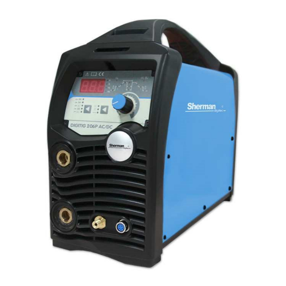
Sherman DIGITIG 206P AC/DC
Before installing and commissioning the device, you must read this instruction
1. GENERAL NOTES
Launch and operation of the device can be made only after a thorough reading of this manual.
Due to continuous technical development unit, some of its features may be subject to modifications
and performance may differ in detail from the descriptions in this manual. This is not a device error,
but the result of progress and continuous work of modification of the device.
Damage to the appliance caused by improper handling causes the loss of warranty. Any alteration of
the charger are forbidden and result in loss of warranty.
2. SECURITY
Equipment operators should possess the necessary qualifications entitling them to perform welding
work:
• should be an electric welder welding electrodes coated and coated gas,
• know the rules of SAFETY operation of power equipment such as welding machines and auxiliary
powered electricity,
• know the rules of SAFETY when handling cylinders and installation of compressed gas (argon), • be
familiar with the content of this manual and operate in accordance with its intended purpose.
WELDING INVERTER
WARNING!
1
V1.2 16.03.08
Advertisement
Table of Contents

Subscribe to Our Youtube Channel
Related Manuals for Sherman DIGITIG 206P


Summary of Contents for Sherman DIGITIG 206P
- Page 1 V1.2 16.03.08 USER MANUAL WELDING INVERTER Sherman DIGITIG 206P AC/DC WARNING! Before installing and commissioning the device, you must read this instruction 1. GENERAL NOTES Launch and operation of the device can be made only after a thorough reading of this manual.
- Page 2 WARNING Welding can endanger the operator and other people in the vicinity. Therefore, during welding should keep special precautions. Prior to welding, you should be familiar with the OCCUPATIONAL HEALTH and SAFETY regulations in force at the place of work. At the time of the electric arc welding methods MMA WELDING and TIG WELDING, there are the following: •...
-
Page 3: General Description
• Put the charger in place for its ease of use. People that support drop should: • have the power to electric arc welding with coated electrodes and TIG • know and comply with the occupational safety and health applicable when carrying out welding work, •... -
Page 4: Arc Force
Supply voltage AC 230V 50 Hz The maximum power consumption MMA: 6.6 kVA, TIG: 4.2 kVA Rated output/duty cycle MMA: 160 A/40% TIG 200 A/40% Nominal voltage without load 60 V Maximum current consumption MMA: 30 A, TIG, 30 A Network security 16 A The weight of the... -
Page 5: Design And Function
5. DESIGN AND FUNCTION The basis for the construction of processing system of electricity welding machines are electronic circuits made in IGBT technology to work in the frequency range above 200 kHz. The principle of operation is based on rectification voltage single phase mains to DC voltage, converted the received voltage on the rectangular frequency, voltage transformation in the scope required by the welding process and then restart after voltage on received voltage. - Page 6 7.2 TIG Current clamp holder should be connected to the socket for negative polarity (2), screw the handle control plug into the socket (4), and the gas connection to the socket coupler (3). Gas hose with regulator and must be attached to the gas nozzle (5) located on the back of the housing. The positive pole (1) connect with the material welded using wire with tick-borne encephalitis.
-
Page 7: Tig Welding
2. The socket the polarity negative 3. Protective gas port 4. Control socket handle TIG WELDING 5. Protective gas connection 6. Main switch 8.2 Control Panel (A) -display of welding parameters The display indicates the parameters during their set and during welding. When lit up, the corresponding LEDs on the side of the display indicates the unit parameter. - Page 8 Prąd spawania Częstotliwość pulsu / ARC FORCE / czas Częstotliwość AC czas trwania impulsu spawania punktowego Narastanie prądu Opadanie prądu Prąd początkowy Prąd krateru Prąd podstawy Powypływ gazu Przedwypływ gazu Balans Adjustment of welding parameters is made by using the multifunctional knob located on the front panel.
-
Page 9: Parameter Settings
Button used to select welding method. The choice of method is indicated a corresponding led. Spawanie punktowe 8.3 protection against overheating The power source is equipped with a thermal overload switch in the compression. When the temperature of the welding will be too high, disconnect the welding current, the code appears on the display E1 will start beeping to signal overheating. - Page 10 The is-the starting current Range 5-160A Tup-rise time currents Adjustment range 0 – 10 s IP-welding current Range 5-160A (MMA)/05-200A (TIG) IB-current base (only in welding with pulse) Range 5-200A Tdown-downslope time Adjustment range 0-15s If direct current crater Range 5-200A Tpost-post flow gas Control range: 0.5-15s Balance-Balance AC-the ratio of the duration of the halves of the positive to the negative...
- Page 11 To initiate the arc in czterotaktu mode, you must approach the electrode to the work piece at a distance of 2 millimeters and press the button on the handle of the burner to turn on the Ionizer. After a valid ARC, you can release the button and the welding lead with a slow motion button. To complete the welding press and release the button on the handle.
-
Page 12: Before You Call Service
The welding process; T3 ~ t4 Note: If the pulsator is enabled, the output current pulses if the pulsator is disabled, the output current is a constant value; T4 : Press the handle. Welding current starts to fall to the current crater. If the pulsator is enabled, falling power is modulated;... - Page 13 Unsatisfactory quality of 1. Replace wear parts. Change the tungsten electrode or gas welds in welding TIG cylinder on the higher-quality materials 2. Check that the shielding gas flows with the appropriate intensity 3. Check the gas supply hose, hose couplings, steel connection status and improved quick couplers 4.
-
Page 14: Wiring Diagram
in covered means of transport. To transport the packed unit must be protected against displacement and provide them with the right position. 15. THE SPECIFICATION OF A SET OF 1. Retrieved DIGITIG 206 p AC/DC 1 PCs. 2. TIG welding holder 1 PCs. 3. Ground cable with clamp tick- borne encephalitis 1 PCs. - Page 15 Warranty is granted for a period of 12 months for entities carrying on economic activities or 24 months from the date of sale to the consumer Warranty will be respected after the presentation by the advertiser of proof of purchase (invoice or receipt) and the warranty card with the typed name of the product, the serial number, the date of sale and bearing the stamp of the point of sale In the case of warranty repair faulty device should be sent to the company TECWELD shipping...
Need help?
Do you have a question about the DIGITIG 206P and is the answer not in the manual?
Questions and answers