Paradox PCS250 Reference And Installation Manual
Gprs/gsm communicator module
Hide thumbs
Also See for PCS250:
- Reference and installation manual (44 pages) ,
- Installation and programming manual (2 pages)

Related Manuals for Paradox PCS250


Summary of Contents for Paradox PCS250
- Page 1 PCS250 - GPRS/GSM Communicator Module V1.0 Reference and Installation Manual PARADOX.COM Printed in Canada - 07/2012 PCS250-EI00...
-
Page 3: Table Of Contents
Using an RS485 Link............. 13 Using an External Power Input ........ 14 Antenna Installation ........15 Antenna Extension Installation (Optional) ..15 Configuring the PCS250 ........ 16 Frequency Band ............16 Bandwidth Saver Mode ..........16 Configuring GSM Network Provider Information .............. -
Page 4: Introduction
SMS. All this is achieved via a simple 4-wire serial connection between the control panel and the PCS250. The PCS250 can be installed up to 2m (6 ft.) from the panel. An external antenna can be installed up to 18m (60 ft.) from the reporting device using an optional antenna and a cable extension, depending on the local signal strength. - Page 5 Included Items • Serial cable • GPRS14 Module Required/Optional Items • Active SIM card (required) • Paradox Plug-In Voice Module VDMP3 (optional) • Antenna extension (optional) • 12 Vdc external power supply (optional) Compatibility • EVO48 and EVO192 panels V2.02 •...
-
Page 6: Overview
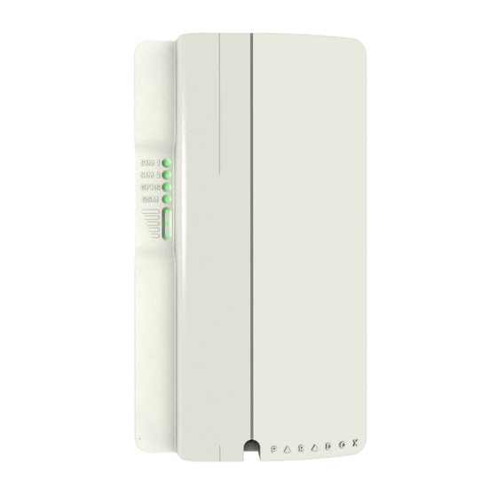
Chapter 2: Overview This section provides an overview of the Paradox PCS250 Communicator Module. It covers technical specifications, light- emitting diode (LED) functionality, and an overview of the PCS250 system components. System Components GPRS14 with dual SIM card slots Audio jack... -
Page 7: Led Feedback
Strength strength of the incoming antenna signal. Communication Loss Upon loss of communication with the panel, the PCS250 LEDs will behave in the following manner: GPRS or GSM LED displays are off; the SIM card and Signal Strength LEDs display their status for about 3 seconds. -
Page 8: Specifications
Specifications The following table describes the technical specifications of the PCS250 Communicator Module. Power Class 4 (2W) @ 850/900 MHz Class 2 (1W) @ 1800/1900 MHz Antenna 70 / 80 / 140 / 170 MHz Bandwidth Antenna Gain <3dBi; impedance 50 ohm Input power >2W peak power... -
Page 9: Connections
GSM network provider. It is important to use SIM Card Tray 1, as SIM Card Tray 2 is reserved for future use. Note: Prior to setting up your PCS250, it is important that the Personal Identification Number (PIN) of the SIM card be disabled. - Page 10 Slide the SIM card into the tray with the cut-off corner towards the bottom left. Close the SIM card tray and slide the tray up to lock it into place. Reconnect the VDMP3 module. Figure 1: SIM Card Installation Page 10 Connections...
-
Page 11: Optional Power Supply Connections
Optional Power Supply Connections The PCS250 is designed to be powered by the control panel. However, if you want the PCS250 to function even if the control panel battery is low, or if power failures are anticipated, an external power supply with a backup battery (such as the PS817) can be used. -
Page 12: Vdmp3 Connection (Optional - Gsm Mode Only)
Where [admin] is the PCS250 default password (if the password has been changed, enter in the new password) and [volume value] is the new volume level. The PCS250 will receive the SMS message and then adjust the volume setting accordingly. -
Page 13: Using An Rs485 Link
Note: It is possible to connect the RS485 A+ and B- lines to a CVT485 installed on a remote panel and power the PCS250 using a separate 12V power source with shorter wire lengths. Figure 3: CVT485 Connection... -
Page 14: Using An External Power Input
Using an External Power Input When an external power input is used as a backup power supply, or when the power lines of a RS485 adapter module (CVT485) are used to power the PCS250, the following connections are required: •... -
Page 15: Antenna Installation
Align the bracket and secure into place using the appropriate mounting hardware. Note: There are two knockout holes in the PCS250 enclosure. The one located at the top of the enclosure is used for an extension cable while the other one is used if an external antenna is installed on the box (rod antenna). -
Page 16: Configuring The Pcs250
Chapter 5: Configuring the PCS250 The PCS250 can be configured for GSM or GPRS reporting. In order for the unit to provide GSM or GPRS reporting, certain configurations must be set. These configurations include modifying the frequency band, configuring GSM network... -
Page 17: Configuring Winload Access
“Labels” or “Messages”. Configuring WinLoad Access The PCS250 Communicator Module provides remote access for upload and download with WinLoad via a GPRS connection. The following site specific sections must be configured for WinLoad access. -
Page 18: Programming And Registering Gprs Reporting Options
Programming and Registering GPRS Reporting Options The following sections describe the options that must be programmed in the panel for GPRS reporting. Control panels with a PCS250 can also report system events to a monitoring station’s IPR512 GPRS/IP Monitoring Receiver. Feature Details... - Page 19 ** Default 10000 † Enter [ ] for blank space Note: When entering into Receiver Settings sections, the LCD screen of the control panel’s keypad will display “Data” for the receiver password and security profiles sections. Configuring the PCS250 Page 19...
-
Page 20: Sms Backup Reporting
PASSWORD MODEM TELEPHONE ] (e.g., Padmin.SMS.5145551111.123456) PASSWORD Wait two minutes. The PCS250 will automatically register to the IPRS-7 receiver. This will automatically program the Backup IP receiver, IP address and port as follows: IP address = 000.000.000.001 Port number = 00001...
Need help?
Do you have a question about the PCS250 and is the answer not in the manual?
Questions and answers