
Subscribe to Our Youtube Channel
Related Manuals for Paradox PCS250G


Summary of Contents for Paradox PCS250G
- Page 1 PCS250G GPRS Communicator Module V1.3 The Vital Link Reference and Installation Manual PARADOX.COM Printed in Canada - 08/2013 PCS250G-EI01...
-
Page 3: Table Of Contents
Configuring GSM Network Provider Information ....16 Configuring WinLoad Access ............18 Programming and Registering GPRS Reporting Options ..18 SMS Backup Reporting ..............20 Configuring the PCS250G for SMS Backup Reporting ..20 Troubles ....................22 Text message notification .............22 SMS Language ...................23 Arm/Disarm System via Text Message........ -
Page 4: Introduction
Using cellular networks, the PCS250G reports to the monitoring station’s automation software via GPRS, ensuring that all communication is fast, reliable, and stable. The PCS250G can be used as a backup to a traditional landline, or as a primary communicator where no landline is available. It also adds remote home control capabilities to a system, allowing you to arm/ disarm with a simple text message (SMS). -
Page 5: Included Items
• E55 panels V3.0 (labels to be programmed via Winload) • E65 panels V2.1 (labels to be programmed via Winload) • MG series V4.0 or higher with K32LCD keypads V1.22 or higher • IP150 Internet Module V2.0 or higher For latest updates visit paradox.com Introduction Page 5... -
Page 6: Overview
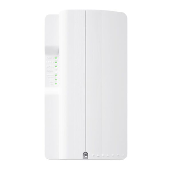
Chapter 2: Overview This section provides an overview of the Paradox PCS250G GPRS Communicator Module. It covers technical specifications, light-emitting diode (LED) functionality, and an overview of the PCS250G system components. System Components GPRS14G with dual SIM card slots InField upgrade connector... -
Page 7: Led Feedback
Strength strength of the incoming antenna signal. Communication Loss Upon loss of communication with the panel, the PCS250G LEDs will behave in the following manner: GPRS LED displays is off; the SIM card and signal strength LEDs display their status for about 3 seconds. -
Page 8: Sim Card Functionality
SIM card connectivity problem. If the panel is disarmed, the PCS250G will try to switch back to SIM card 1 after a 15 minute delay. If there is a connection problem on SIM card 1, it will retry to switch back to SIM card 1 every 15 minutes, or until the system is armed. -
Page 9: Specifications
SMS recipients. Also, upon the closure of the PCS250G’s tamper switch there is a 30s delay before the PCS250G sends out a “tamper close” status to the panel. -
Page 10: Connections
Important: If provider redundancy is not required (SIM card 2), ensure that SIM Card Tray 1 is used. Note: Prior to setting up your PCS250G, it is important that the Personal Identification Number (PIN) of the SIM card be disabled. -
Page 11: Gprs Connections
SIM CARD SIM 2 GPRS Connections The PCS250G is connected directly from the serial cable connector located on the bottom of the unit to the serial connector of the panel using the provided serial cable. Figure 2: GPRS Serial Connections... -
Page 12: Communication Bridge
Communication Bridge When using a modified IP150 cable, the IP150 Internet Module and the PCS250G are interlinked to the control panel and communicate together to report alarms to the IP/GPRS monitoring receiver (IPRS-7 or IPR512). In the case of IP... -
Page 13: Optional Power Supply Connections
Optional Power Supply Connections The PCS250G is designed to be powered by the control panel. However, if you want the PCS250G to function even if the control panel battery is low, or if power failures are anticipated, an external power supply with a backup battery (such as the PS817) can be used. -
Page 14: Installation
(rod antenna). Module Installation The PCS250G must be securely mounted on a wall or similar surface. It is important to mount it as far away as possible from any electronic equipment. Ensure that it is mounted as high as possible to ensure protection from RF interference. -
Page 15: Configuring The Pcs250G
Chapter 4: Configuring the PCS250G The PCS250G can be configured for GPRS reporting. In order for the unit to provide GPRS reporting, certain configurations must be set. These configurations include configuring GSM network provider information, configuring the PCS250G for WinLoad access, and registering and programming GPRS reporting options. -
Page 16: Configuring Gsm Network Provider Information
Programming Phone Numbers At The Panel To program your PCS250G to forward all SMS coming in from a specific number, simply add the letter "P" in front of the phone number you program through the panel: • You would program (P5145551234) to forward •... - Page 17 Note: When programming the second SIM card, replace APN1 with APN2 and VAPN1 with VAPN2 in the SMS command. Refer to “List of SMS Commands” on page 25 to view the commands for SIM card 2. Configuring the PCS250G Page 17...
-
Page 18: Configuring Winload Access
Programming and Registering GPRS Reporting Options The following sections describe the options that must be programmed in the panel for GPRS reporting. Control panels with a PCS250G can also report system events to a monitoring station’s IPR512 GPRS/IP Monitoring Receiver. Feature Details... - Page 19 ** Default 10000 † Enter [ ] for blank space Note: When entering into Receiver Settings sections, the LCD screen of the control panel’s keypad will display “Data” for the receiver password and security profiles sections. Configuring the PCS250G Page 19...
-
Page 20: Sms Backup Reporting
SMS Backup Reporting The PCS250G GPRS Communicator Module supports SMS backup reporting to an IPRS-7 (IP/GPRS PC Receiver Software) when used in conjunction with a compatible Paradox control panel. • SP5500/SP6000/SP7000 v4.76 • EVO192 v2.65 • SP4000/SP65 v4.94 This advanced feature assures continuous communication with the protected premises. - Page 21 Clearing the P[password].SMS.clear programmed SMS parameters Note: If SMS registration fails, you can use registration section (SP Series [949], EVO Series [2991]) to restart the SMS registration process on the backup receiver. Configuring the PCS250G Page 21...
-
Page 22: Troubles
GPRS, the PCS250G can also send text messages (SMS) to the end user (up to 16 cell phone numbers). The PCS250G can send text messages for any control panel event due to its proprietary communication through the panel’s serial port. -
Page 23: Sms Language
SMS messages per event reported and other languages will use special LCD characters not supported on all cell phones. Refer to the paradox.com website for the list of languages that are supported, that generate two SMS messages, or that use special characters. -
Page 24: Arm/Disarm System Via Text Message
SIM card switch. The text message command has a specific format and specific elements that must be sent to the phone number of the PCS250G module. The format is as follows: SMS Text Message Format C[USER CODE].[ACTION].A[PARTITIONS].[PHONE NUMBER]... -
Page 25: List Of Sms Commands
Used for GPRS remote access number] P[password].IP.[call back phone Used to obtain the IP number] address and IP port of the PCS250G and whether or not the “bandwidth saver” option is being used Used to reset the PCS250G P[password].RESET P[password].BWS.ON... -
Page 26: Upload/Download
(WinLoad and NEware) has been set up for port forwarding to ensure proper system functionality. To receive the IP address of the PCS250G via text message you must use a cellular phone and enter: P[TCP/IP password].IP.[phone number to answer back] e.g., Padmin.IP.5551231234... -
Page 27: Private Network
If your SIM card provider is on a private network, communication to the PCS250G must first be established via an SMS message. When the SMS message is sent to the PCS250G, the PCS250G will then initiate a connection with WinLoad. Once communication is established, firmware upgrades, as well as upload and download configurations and system programming can begin. -
Page 28: Module Supervision
GPRS service or loss of communication with the control panel. Unique to Paradox, the PCS250G can supervise the presence of the control panel. If communication with the control panel is lost, the PCS250G will send an SMS message. -
Page 29: End User Sms Programming
Set which phone numbers (up to 8 with MG/SP/ E-Series or 16 with Digiplex EVO) will receive text messages sent by the PCS250G to report system events. • Select from which area the PCS250G will send text messages (per phone number). • Select which event groups (alarm, arm/disarm, trouble and trouble restore) will generate text messages. -
Page 30: View Gprs Ip Information
IP Address: Access this to determine which IP address to enter in the WinLoad or NEware GPRS connection settings. The IP address is determined automatically when the PCS250G connects to the GSM network. In order to properly read the IP address assigned, the GPRS LED must be on. •... - Page 31 To access Master Programming, enter the [ ] then MASTER CODE press [0]. In Master Programming, press [2] to display the PCS250G IP information. The first screen displays the PCS250G IP Address. Press [] to access the next screen. The second screen displays the PCS250G IP Port. Press [] to access the third screen.
-
Page 32: Text Messages
Chapter 7: Text Messages The following table lists all pre-defined text messages that can be sent. These messages follow the 8-bit or 16-bit SMS protocol and include the elements from the information column. The messages will also use the labels programmed in the system for the area name, zone name, user name, and module name. - Page 33 Arming/Disarming Messages Message Information* Arming 1-2-3 Arming with remote 1-2-3 Arming through internet 1-2-3 Arming through end-user PC software 1-2-3 Arming through voice module (phone) 1-2-3 Arming through SMS 1-2-3 Arming with keyswitch 1-2- 4 Arming through Installer PC software One-touch arming Auto-arming Disarming...
-
Page 34: Trouble Event Messages
Trouble Event Messages Message Information* AC power failure on control panel Battery failure on control panel Bell overload on control panel Bell disconnected from control panel Phone line trouble on control panel Pager communication from control panel failed 1- 4 Central station communication from control panel failed 1- 4 Voice communication from control panel failed Installer PC communication from control panel failed... - Page 35 Trouble Restore Messages Message Information* AC power restored on control panel Battery power restored on control panel Bell restored on control panel Bell connected on control panel Phone line restored on control panel Central station communication from control panel restored Date and time restored on control panel System wireless communication restored Tamper restored on module...
-
Page 36: Troubleshooting
Chapter 8: Troubleshooting This chapter describes some basic issues that may occur on your PCS250G. It is not intended to be a complete guide for all possible issues. If you have tried the possible solutions provided below and are still experiencing technical issues, contact your installer. - Page 37 Bandwidth saver mode ..............15 Cancel SMS ..................31 Communicating Using Text Messages ........15 Compatibility ..................5 Configuring the PCS250G ............. 15 Consumption ..................9 Control panel ..........4, 8, 10, 11, 16, 18, 19 presence ................... 28 reporting events ..............22 Digiplex EVO ................
- Page 38 Firmware upgrades................27 Forwarding SMS Messages ............16 Front cover..................10 GPRS ..................7, 11, 15, 22 channel..................20 network ..................16 remote access ................. 25 reporting................... 18 Ground ....................13 cell phone network............... 28 network connection loss............. 28 GSM/GPRS modem ................20 Included Items..................
- Page 39 Operating Temperature..............9 PCS250G ....................1 communication loss ..............7 configuration ................15 LED feedback ................7 overview ..................6 reset.................... 25 specifications ................9 Phone number ............. 25, 26, 29, 30 Power input ................... 9 Power supply ..................13 connections ................
- Page 40 APN .................. 25 disable bandwidth saver mode........25 enable bandwidth saver mode ........25 GPRS remote access ............. 25 IP address ................. 25 reset PCS250G ................ 25 signal strength................ 25 SP Series................... 5, 20 Specifications..................9 Supervision ..................28 System Components................
- Page 41 Notes ______________________________________________________ ______________________________________________________ ______________________________________________________ ______________________________________________________ ______________________________________________________ ______________________________________________________ ______________________________________________________ ______________________________________________________ ______________________________________________________ ______________________________________________________ ______________________________________________________ ______________________________________________________ ______________________________________________________ ______________________________________________________ ______________________________________________________ ______________________________________________________ ______________________________________________________ ______________________________________________________ ______________________________________________________ ______________________________________________________ ______________________________________________________ ______________________________________________________ ______________________________________________________ ______________________________________________________ ______________________________________________________ ______________________________________________________ ______________________________________________________ ______________________________________________________ ______________________________________________________ ______________________________________________________ ______________________________________________________ ______________________________________________________ ______________________________________________________ ______________________________________________________ ______________________________________________________ ______________________________________________________ ______________________________________________________ ______________________________________________________ ______________________________________________________ ______________________________________________________ ______________________________________________________ ______________________________________________________...
- Page 42 As with traditional land-line reporting an acknowledgement (kiss-off ) signal is used when the IP150 or PCS250G sends a valid message to a receiver that is typically used in a monitoring station. This acknowledgement is generated within 5 seconds.
- Page 44 To learn more about the complete line of Paradox products, please visit www.paradox.com.
Need help?
Do you have a question about the PCS250G and is the answer not in the manual?
Questions and answers