Table of Contents
Advertisement
Advertisement
Table of Contents

Related Manuals for Paradox PCS200


Summary of Contents for Paradox PCS200
- Page 1 PCS200 Communicator Module V2.2 Reference and Installation Manual...
- Page 2 Warranty For complete warranty information, please visit www.paradox.com/terms. Your use of the Paradox product signifies your acceptance of all warranty terms and conditions. PCS200, Magellan, Spectra SP, EVO, and WinLoad are trademarks or registered trademarks of Paradox Ltd. or its affiliates in Canada, the United States and/or other countries.
-
Page 3: Table Of Contents
Installation ........................13 Wall-Mount Installation............... 13 Antenna Installation ................14 Antenna Extension Installation (Optional) .......... 14 Configuring the PCS200 ..................15 Modifying the Frequency Band ............15 Bandwidth Saver Mode ..............15 Configuring GSM Network Provider Information ........ 16 Configuring WinLoad Access ............. 16 Programming GSM Reporting Options .......... - Page 4 Module Supervision Options ................. 23 End User SMS Programming............. 24 End User SMS Programming with Digiplex EVO ........24 End User SMS Programming with MG/SP / E-Series ......24 View GSM IP Information..............25 Viewing GSM IP Information with Digiplex EVO ........26 Viewing GSM IP Information with MG/SP / E-Series ......
-
Page 5: Introduction
GPRS. All this is achieved via a simple 4-wire serial connection between the control panel and the PCS200. The PCS200 can be installed up to 2m (6 ft.) from the panel. The device’s antenna can be installed up to 18m (60 ft.) from the reporting device using an optional antenna cable extension, depending on the local signal strength. -
Page 6: Included Items
• 4-Phillips screws (top cover) • Antenna • Removable power terminal Required/Optional Items • Active SIM card (required) • Paradox Plug-In Voice Module VDMP3 (optional) • Antenna extension (optional) Compatibility • EVO48 and EVO192 panels V2.02 • K641 and K641R keypads V1.51 or higher •... -
Page 7: Overview
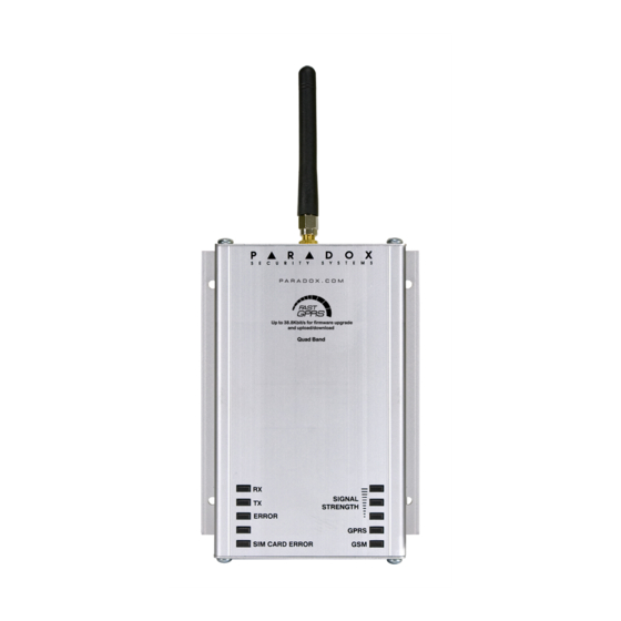
SIM card slot (supports standard GSM provider SIM cards) System LEDs (refer to “LED Feedback” on page 7) Antenna cable connector Mounting holes - used to mount the PCS200 to a wall or similar type surface Aluminum enclosure Bandwidth selection switch... - Page 8 The following table provides a description of the PCS200 Communicator Module LEDs. Flashing green: receiving data Flashing green: transmitting data Error Red: module is not communicating with control panel. LED will be lit on power-up until a connection has been established.
-
Page 9: Specifications
Specifications The following table describes the technical specifications of the PCS200 Communicator Module. Power Class 4 (2W) @ 850/900 MHz Class 2 (1W) @ 1800/1900 MHz Antenna 70 / 80 / 140 / 170 MHz Bandwidth Antenna Gain <3dBi; impedance 50 ohm Input power >2W peak power... -
Page 10: Connections
In order to activate your SIM card, you must contact your local GSM network provider. Note: Prior to setting up your PCS200, it is important that the Personal Identification Number (PIN) of the SIM card be disabled. Refer to your cellular phone’s manual for more information on how to disable the PIN. -
Page 11: Gsm Vs. Gprs Connections
GSM vs. GPRS Connections The PCS200 is connected directly from the serial cable connector located on the bottom of the unit to the Paradox control panel using the provided serial cable. Note: GSM and GPRS reporting cannot be conducted simultaneously. To switch reporting methods, connect the serial cable to the control panel’s Serial... - Page 12 Where [admin] is the PCS200 default password (if the password has been changed, enter in the new password) and [volume value] is the new volume level. The PCS200 will receive the SMS message and then adjust the volume setting accordingly.
-
Page 13: Installation
PCS200 and how to mount and connect the antenna. Wall-Mount Installation The PCS200 must be securely mounted on a wall or similar surface. It is important to mount the metal box as far away as possible from any electronic equipment. Ensure that the metal box is mounted as high as possible to ensure protection from RF interference and to maximize the signal quality. -
Page 14: Antenna Installation
Antenna Installation The PCS200 antenna connects to the antenna cable connector located on the PCS200 PCB board. The antenna cable’s connector is located on the outside, top-part of the PCS200 Communicator Module. To Connect the Antenna: Position the antenna onto the antenna connector. -
Page 15: Configuring The Pcs200
Chapter 5: Configuring the PCS200 The PCS200 can be configured for GSM or GPRS reporting. In order for the unit to provide GSM or GPRS reporting, certain configurations must be set. These configurations include modifying the frequency band, configuring GSM... -
Page 16: Configuring Gsm Network Provider Information
Configuring GSM Network Provider Information To connect the PCS200 to the GPRS network, certain registration parameters must be set (supplied by your GSM network provider). These parameters include the Access Point Name, APN User Name, and the APN Password. To begin the configuration of your GSM network provider information, enter the section programming in your panel. -
Page 17: Programming Gsm Reporting Options
Programming and Registering GPRS Reporting Options The following sections describe the options that must be programmed in the panel for GPRS reporting. Control panels with a PCS200 can also report system events to a monitoring station’s IPR512 GPRS/IP Monitoring Receiver. -
Page 18: Troubles
MG/SP/E Trouble Group MG/SP/E Trouble Sub-Group [4] Communication Trouble [7] Fail to communicate with receiver [9] GSM network failure ] IP Receiver unregistered (IP/GPRS) [10] Module supervision loss [9] GPRS/GSM module EVO Trouble Group EVO Trouble Sub-Group Configuring the PCS200 Page 18... - Page 19 [9] Communication Trouble [5] Fail to communicate with receiver 1 [6] Fail to communicate with receiver 2 [7] Fail to communicate with receiver 3 [8] Fail to communicate with receiver 4 [9] IP Receiver unregistered (IP/GPRS) Page 19 Configuring the PCS200...
-
Page 20: Text Message Notification
In addition to reporting control panel events via a GSM cell phone network through GSM and GPRS, the PCS200 can also send text messages (SMS) to the end user (up to 16 cell phone numbers). The PCS200 can send text messages for any control panel event due to its proprietary communication through the panel’s serial port. -
Page 21: Arm/Disarm System Via Text Message (Gsm Only)
It is possible to arm or disarm your system by sending an SMS text message from any cell phone. The message must be sent to the PCS200’s phone number, as determined by the cell phone network provider. The text message command has a specific format and specific elements that must be sent to the phone number of the PCS200 module. -
Page 22: Upload/Download
(WinLoad and NEware) has been set up for port forwarding to ensure proper system functionality. To receive the IP address of the PCS200 via text message you must use a cellular phone and enter: P[TCP/IP password].IP.[phone number to answer back] i.e. -
Page 23: Upgrading The Firmware
Double-click the account you wish to establish communication with from the Account Group list. On the menu bar, click System and then click Wait for call. Enter the SMS text information to be sent to the PCS200 as you see it on screen i.e., “Padmin.A10.10.1.100.P10001”. Upgrading the Firmware The PCS200 firmware can be upgraded using the WinLoad software application. -
Page 24: Module Supervision Options
Unique to Paradox, the PCS200 can supervise the presence of the control panel. If communication with the control panel is lost, the PCS200 will send an SMS message. In GSM mode only, the PCS200 can report to the central station that communication to the control panel has been lost (red Error LED will light up). -
Page 25: End User Sms Programming
With Master Programming, you can: • Set which phone numbers (up to 8 with MG/SP/ E-Series or 16 with Digiplex EVO) will receive text messages sent by the PCS200 to report system events. • Select from which area the PCS200 will send text messages (per phone number). -
Page 26: View Gsm Ip Information
IP Address: Access this to determine which IP address to enter in the WinLoad or NEware GPRS connection settings. The IP address is determined automatically when the PCS200 connects to the GSM network. In order to properly read the IP address assigned, the GPRS LED must be on. -
Page 27: Viewing Gsm Ip Information With Digiplex Evo
MASTER CODE In Master Programming, press [2] to display the PCS200 IP information. The first screen displays the PCS200 IP Address. Press [] to access the next screen. The second screen displays the PCS200 IP Port. Press [] to access the third screen. -
Page 28: Pre-Defined Text Messages
Chapter 8: Pre-Defined Text Messages The following table lists all pre-defined text messages that can be sent. These messages follow the 8-bit or 16-bit SMS protocol and include the elements from the information column. The messages will also use the labels programmed in the system for the site name, area name, zone name, user name, and module name. -
Page 29: Arming/Disarming Messages
Arming/Disarming Messages Message Information* Arming 1-2-3-4 Arming with remote 1-2-3-4 Arming through internet 1-2-3-4 Arming through end-user PC software 1-2-3-4 Arming through voice module (phone) 1-2-3-4 Arming through SMS 1-2-3-4 Arming with keyswitch 1-2-3-5 Arming through Installer PC software 1-2-3 One-touch arming 1-2-3 Auto-arming... -
Page 30: Trouble Event Messages
Trouble Event Messages Message Information* AC power failure on control panel Battery failure on control panel Bell overload on control panel Bell disconnected from control panel Phone line trouble on control panel Pager communication from control panel failed 1-2-5 Central station communication from control panel failed 1-2-5 Voice communication from control panel failed Installer PC communication from control panel failed... -
Page 31: Trouble Restore Messages
Trouble Restore Messages Message Information* AC power restored on control panel Battery power restored on control panel Bell restored on control panel Bell connected on control panel Phone line restored on control panel Central station communication from control panel restored 1-2-5 Date and time restored on control panel System wireless communication restored... -
Page 32: Index
Bandwidth saver mode 15 IP Address 25 IP Port 25 IPR512 GPRS/IP Monitoring Re- Cancel SMS 26 ceiver 17 Compatibility 6 Configuring the PCS200 15 Consumption 9 K641 6 K641R 6 Default volume 12 Digiplex EVO 24 LED 7, 15... - Page 33 NEware 21 On-Site Firmware Upgrade 22 Operating Temperature 9 PCS200 reset 20 Power input 9 Pre-defined text messages 27 Private Network 21 Public Network 21 Registering and programming GPRS reporting options 15 Registration parameters 16 Remote Firmware Upgrade 22 Required/Optional Items 6...
- Page 34 Text message notification 19 Trouble Event Messages 29 Trouble Restore Messages 30 Troubles 18 TX 8, 20 Upgrading the Firmware 22 Upload/download 21 User PC Software Password 25 VDMP3 11 VDMP3 Connection 11 View GSM IP Information 25 Volume 12 Wait for call 22 Wall-Mount Installation 13 WinLoad 21...
-
Page 35: Notes
Notes _____________________________________________________________ _____________________________________________________________ _____________________________________________________________ _____________________________________________________________ _____________________________________________________________ _____________________________________________________________ _____________________________________________________________ _____________________________________________________________ _____________________________________________________________ _____________________________________________________________ _____________________________________________________________ _____________________________________________________________ _____________________________________________________________ _____________________________________________________________ _____________________________________________________________ _____________________________________________________________ _____________________________________________________________ _____________________________________________________________ _____________________________________________________________ _____________________________________________________________ _____________________________________________________________ _____________________________________________________________ _____________________________________________________________ _____________________________________________________________ _____________________________________________________________ _____________________________________________________________ _____________________________________________________________ _____________________________________________________________ _____________________________________________________________ _____________________________________________________________ _____________________________________________________________ _____________________________________________________________ _____________________________________________________________ _____________________________________________________________ _____________________________________________________________ _____________________________________________________________ _____________________________________________________________ _____________________________________________________________... - Page 36 _____________________________________________________________ _____________________________________________________________ _____________________________________________________________ _____________________________________________________________ _____________________________________________________________ _____________________________________________________________ _____________________________________________________________ _____________________________________________________________ _____________________________________________________________ _____________________________________________________________ _____________________________________________________________ _____________________________________________________________ _____________________________________________________________ _____________________________________________________________ _____________________________________________________________ _____________________________________________________________ _____________________________________________________________ _____________________________________________________________ _____________________________________________________________ _____________________________________________________________ _____________________________________________________________ _____________________________________________________________ _____________________________________________________________ _____________________________________________________________ _____________________________________________________________ _____________________________________________________________ _____________________________________________________________ _____________________________________________________________ _____________________________________________________________ _____________________________________________________________ _____________________________________________________________ _____________________________________________________________ _____________________________________________________________ _____________________________________________________________ _____________________________________________________________ _____________________________________________________________ _____________________________________________________________ _____________________________________________________________ _____________________________________________________________...
- Page 38 Monday to Friday from 8:00 a.m. to 8:00 p.m. EST. For technical support outside Canada and the U.S., call 00-1-450-491-7444, Monday to Friday from 8:00 a.m. to 8:00 p.m. EST. Please feel free to visit our website at www.paradox.com. PARADOX.COM PCS200-EI08 03/2012...
Need help?
Do you have a question about the PCS200 and is the answer not in the manual?
Questions and answers